Redox Keyboard With Wooden Case
by cbosdonnat in Workshop > Woodworking
5086 Views, 74 Favorites, 0 Comments
Redox Keyboard With Wooden Case

Split keyboards are ergonomic but expensive and I didn't want to spent several hundred dollars to get one. Deciding which split keyboard model to build took me months thinking and browsing, but I settled on a Redox because the layout seemed to fit my hands, was one of the cheapest ones to make and looked easy for me to build.
Writing an instructable on how to build will help others to get a hand on affordable ergonomic keyboards I hope.
One of the things that cost a lot is the 3D printed case, even more when you don't have a 3D printer at hand. I have lots of reclaimed wood and some woodwork tools and skills so I decided building a wooden case to reduce the price a lot.
Manually wiring also removes the cost of the PCB.
If you don't have a lot of room in your garage to have a router table, a table saw and all those big and heavy tools, this project is for you! Since I don't have them either this guide will show how to do using portable power tools and hand tools.
This guide will show how to build the keyboard, feet for tenting and wrist rests.
Supplies


Keyboard supplies:
- Reclaimed wood. I took about 500mm in a 75x45mm walnut bed frame for the walls and 550mm in 160x7mm board from the same deb frame. Use the scraps of those for the feet.
- 2 arduino micro pro
- 2 TRRS plugs
- TRRS cable
- Old phone micro-USB cable
- 70 key switches. If you are new to the keyboard world like me, mind that there are optical switches too: don't buy them!
- 70 Keycaps
- 70 1N4148 Diodes (in fact sold by 100)
- Old network cables
- 2 momentary switches. I got them from broken electronic devices
- Wood screws 3mm diameter and 12mm length. I got mine from old furniture
- Old canning rubber ring. After some time using the keyboard it doesn't grip enough. I took some old rubber cleaning glove to fix this issue and it seems to work better.
- Extra strong glue or CA glue
- Wood glue
- Regular (or spray) glue
- Varnish
- 2mm acrylic. I used left over from other projects
I went with a TRRS cable and the corresponding plugs to connect to two halves. you can save a little more if you have 2 female USB plugs from an old computer or USB-capable device. Any 4 wire connection works, even 3 wires if you use serial protocol and no LED backlighting. Check out the web, you can event coil your cable!
Wrist rest supplies:
- Reclaimed wood. I took a 370x75x20mm pine scrap
This howto shows how to create leather-covered wrist rests. In such a case, the following items are needed. I got them from an old arm chair I repaired, but wrist rests could be only varnished wood.
- Felt fabric or similar soft and thick fabric
- Leather or other smooth but hard fabric
- Upholstery tacks
Tools:
- Miter saw
- Portable router
- Jig saw
- Belt sander
- Chisels
- Saw
- Clamps
- Sandpaper of various grits
- Hammer
- Utility knife
- Printer
- Drill
- 13mm drill bit
- 2mm and 3mm manual drills
- Files
Time:
I didn't track the time I spent on this project. This is the kind that spans on multiples evenings and week-ends. After the fact I estimated the whole thing without the trial and errors to about 26 hours.
Cutting the Key Switches Holes


I adapted the design from sako33's 3D printing model. Open the DXF file and print it at the 1:1 scale. Check your print that each key hole has 14mm sides: this is important for the key switches to fit perfectly!
Glue the printed templates on a 5mm thin wood board using regular glue.
Draw the diagonals of each key hole and punch a tiny hole with a wood drill bit for instance at the intersection.
Cut along the key hole sides using a utility knife and remove the paper of the key hole. This is not mandatory, but drilling tears off the paper and makes it harder to cut precisely along the lines.
To cut the holes use the 13mm drill bit and center it in the mark previously made in the center of the square. Afterwards use a chisel to square the hole along the lines. It's is good to use one of the switches to verify that it has a tight fit.
Note that if you don't have a 13mm drill bit at hand you can use any smaller one, it will just involve more chisel work after. In any case don't use a 14mm one since it would be harder to recover if the hole is not perfectly centered.
Downloads
Cutting the Plates

Once all holes are cut, roughly cut the plates along the outer lines using a jig saw. Then remove the remaining to the lines using the belt sander. I use a home-made belt sander stand to help in that process, check out other instructables to build yours.
If you don't have a jig saw, replace the curved sides of the plates with straight lines and cut using a regular saw or just be patient and use chisels to close up to the lines. Same if you don't have a belt sander at hand, you can use chisel or sand paper to sand to the lines.
Remove the remaining paper and sand the plates using grain from 80 to 320.
Cutting the Case Walls

Sadly I have taken less pictures of the beginning of this step, I will try to explain my best how I did it. I also didn't have the DXF at hand when creating my own version, so it should be easier.
Cutting each piece
Print two copies of the wall template DXF at the 1:1 scale, one for each half.
Cut the template for each side. Note that there are three lines: the middle (dotted in the picture above) one is for the groove where the plate will fit, so cut the external plain lines. You should end up with 5 pieces of paper for each half. Flip one set of pieces for the right half. Mark them to avoid confusion later in the process.
Glue each piece on a wood board about 25mm thick. The exact thickness is not very important as part of it will be sanded away. It needs to be at least 23mm thick.
Cut each piece. For the straight pieces you can use a miter saw or a hand saw. For the curved ones use the jig saw and finish by sanding them to the outer lines.
For more precision, don't cut the angles now!
Downloads
Routing the Vertical Slot


Before continuing check the drawing of the section of each wall. The bottom part has no size and is only here to help cutting the 3mm vertical slot above it: it helps stabilizing the router.
Flip the walls to have the inner side up, clamp it in a moxon vise to guide the router. Check out Instructables for how to build one easily!
Set the router depth to 3mm and use a 16mm router bit to create the slot.
For the curved pieces, proceed in the same way, but turn the piece several times to follow more or less the curve. It is not critical for the slot to precisely follow the curve since the plate can be adjusted to fit later.
Assembling the Walls


Cut roughly and sand the ends to the angle line.
Sand away the routing helper at the bottom of the walls.
Using a hand saw cut an 8mm slot at about 8mm from the top of the side in each corner.
Cut wood pieces as thick as the created slot and fit them tightly in each corner. Those will be used as connectors to have a stronger connection between all pieces. I used the left over after the walls cuts, but a wood of a different color can add a nice effect.
Try to assemble all pieces with the connectors without glue and fix where needed. Number every corner and connector to avoid mixing them while trying and gluing. Once you are satisfied, glue each connector, the slots and the side pieces together using wood glue.
Let the glue dry and then trim the connectors flush with the case surface.
There may be tiny holes at this point. Mix a drop of wood glue with wood sand dust and fill these holes with that paste. Let the glue dry and sand the bumps. Repeat this operation until you are satisfied with the surface.
Prepare the Bottom Part

This step is mostly theoretical since in my project I created the acrylic bottom after everything else. However it makes more sense to cut it before varnishing the case. By creating the bottom after everything is ready makes it hard to precisely align the acrylic with the case edges.
I used scraps of acrylic I had from other projects: this explains why it only covers half the case on the picture: I did the same for the other half with another scrap.
For the bottom use either a thin wood board or like me scraps of 2mm acrylic.
- Place the case walls upside down with the acrylic on top of them and draw the shape with a sharpie
- Cut the acrylic with a jigsaw a little away of the lines
- Clamp the acrylic to the case and sand them together with the belt sander, first with coarse grit (80) and finish with fine grit (320)
Test the Plates With the Walls

Try now to fit the plates in their corresponding walls. Don't push too hard if it doesn't fit, but look for the spots to sand or cut to fit nicely.
Note that there is no need for a tight fit between the plate and the case since there will be pieces to hold the plate in place screwed below.
Sand all outer surfaces with grits from 80 to 320, clean and varnish everything visible. Make sure not to drop too much varnish within the key switches holes. Depending on the type of varnish you use, you may need to sand again before the second layer with small grit to remove the wood fibers.
Once all varnish layers are applied and dry, test fit all key switches. Be aware that the holes may be a little tighter due to the varnish. In such a case gently clear the hole again with a chisel or sand paper until the key switch fits reasonably tightly. Forcing too much could break the plate!
Cutting Slots for the Arduinos


It is time now to cut the walls a bit more to fit the Arduino and their micro USB slot, the reset button and the TRRS connectors.
Start by centering the Arduinos on the back walls. Draw the edges with a sharp pencil.
Using a chisel, dig a 7mm deep slot from the top.
Don't cut too near the edge lines, better remove the sides little by little at the end when trying to fit the Arduino to allow a tight fit.
Even this way mine aren't tight enough I had to add something to hold them in place when plugging the cable (See the last picture after the wiring step).
To dig the micro USB opening, flip the case to have the outer side of the wall on a martyr board. Place the arduino and draw a line along the connector. Measure the connector and draw the other line. Proceed gently with the chisel along the two long sides of the holes.
When the coming to the other side, finish opening the hole with the chisel from the outside face for a cleaner aspect.
Cutting Slots for the TRRS Connector and Reset Button


The reset buttons and the TRRS connectors are a little easier since the opening just has to be drilled.
Measure the TRRS connector outside. In my case a hole of 5mm diameter was needed. For the reset button a 2mm hole is enough. I used a manual drill for it, but if you don't have one, you may use a tiny screw.
Those holes need to be centered with the place where the components will be. The position of those slots is not that important, but keep the TRRS holes as close from the other side of the keyboard as possible. I also made everything symmetric.
First drill the holes and then carefully measure the components and report those on the walls around the corresponding hole.
Just as for the Arduino slot, dig the slots using a chisel and cut them for a tight fit to avoid gluing any of the component. Also keep in mind that he TRRS connector has legs to solder to and those need to fit in the wall too.
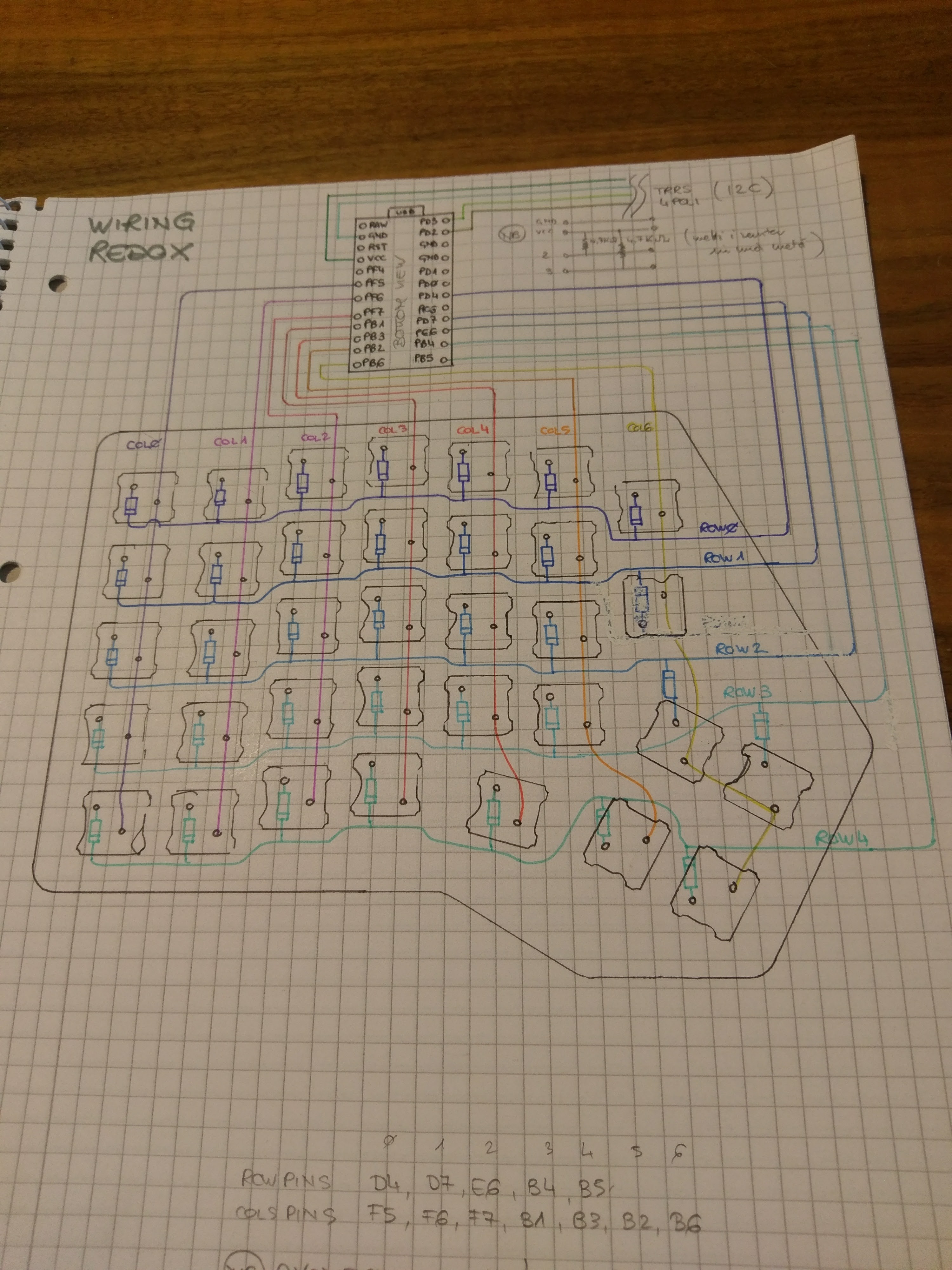
Wiring


There are plenty of good tutorials on how to hand wire a keyboard on the web and I mostly followed a mix of them.
For the column wires, cut an old network cable and use the 4 pairs of cable within it. These cables are strong enough to stay in place while working if you lock them with the key switches pins... but don't twist them too much: they break easily!
For the rows, twist the diode anode (the end without the black bar) around a wire, hook this loop on the switch pin and solder the cathode leg with the next one. Just as Mattia Dal Ben did in his initial version I used an old IDE cable to connect the rows. Just pay attention when separating the IDE cable wires to not tear off the insulation.
When soldering to the Arduino, check out Mattia's drawing but mind that the arduino is flipped in my pictures. Also consider that the two halves are mirrored: column 0 is the pinky's column in both halves!
Don't copy my mistake in the pictures showing the left hand wiring, I wired the columns in the wrong order: Column 0 is the pinky's one!
In my pictures you may see that I haven't soldered the two 4.7kΩ resistors. This is because I am not yet decided whether to add RGB back lighting or not. Thus I decided to go with serial connection between the two halves and left the RGB pins free on the TRRS. See the redox documentation on how to solder the RGB LED strips.
Tips
- Make sure to add an insulation layer between the grid wiring and the Arduino.
- Test now that your keyboard works OK. I had an n entered every time I plugged the keyboard and discovered that the column insulation had melt under the diode leg around that key!
- Wiring the columns from the front of the keyboard to the Arduino (as you can see on the right hand picture) is way easier to handle.
Holding It Together


In the current state the plates are still moving in the case. This step is about to add some wood pieces to hold it in place.
Pick a few 7mm thick hard wood scraps and cut them approximately as show in the picture. None of the dimensions here is really important as long as you leave holes for legs in the corners if you want tenting.
Note that the back corner holder has a strange shape: the hole in the corner is for the foot and that piece is also used to hold the TRRS connector in place.
To fix these holders in the walls better use small screws like 3mm of diameter and about 12mm length.
To avoid the wood to crack when screwing, drill 3mm holes in the holders where the screws will be driven.
Also drill 2mm holes to attach a bottom later.
In the last picture you will see the correct wiring and two pine bars. I had to cut those to hold the Arduinos in place when plugging the cable.
Feet for Tenting


The tenting is done using feet. In the picture you can see I initially cut 3 for each half, but the middle one is useless: you only need two.
I have to admit that to create the feet I made no plan at all: I just eyeballed it all and used chisels to cut them in the scraps of wood from the walls.
Basically the idea is to measure the rough length of the foot, cut the end that will go between the plate holders, place it and see where to cut the bottom face to have it flat on the table.
In all these cuts, progress slowly: you want a tight fit of the feet in the holes to avoid them to drop when you lift the keyboard.
Add the Acrylic Bottom


Place the previously cut acrylic faces properly, mark where to drill the screw and feet holes.
Drill the screw holes using a 3mm drill bit and use a countersink bit to make room for the screw heads. I operated the countersink bit manually to avoid going too far in the acrylic and it's easy to cut any way.
For the feet drill a hole slightly smaller than the shape of the foot hole and finish with a small file and or a utility knife. Using a chisel was also helpful for me.
Screw the acrylic to the holders using the same small screws.
For those, like me, who create the acrylic bottom after everything else:
- Drill the screw holes as mentioned above
- Screw the non-adjusted acrylic
- Mark the shape of the keyboard half using a utility knife along the case walls as shown in the picture
- Unscrew the acrylic
- Sand the acrylic to the line and screw it again
Add the Key Caps
Insert all the key caps to their switches.
Wrist Rests Wood Piece


Creating the wrist rests could almost be a separate instructable. These wrist rests are made of the following layers:
- a thick wood piece for the stability
- felt fabric for softness and comfort
- leather to wrap it all
Of course you can skip some of these steps if you only want the wood layer.
Cutting the wood piece
Since the keyboard halves have a curvy front shape, this curve needs to be drawn on a sheet of paper for a nice fit. Add 7cm to the sides to the keyboard for the wrist rests and that’s it for the template!
Remove about 3mm from each side of the wrist rests if you want them to nicely align with the keyboard once finished. This is due to the leather adding thickness to the wood. You will see in my final pictures that I forgot to take this into account.
Cut the template and glue it on a piece of wood about as thick as the keyboard. Using softwood or bad looking wood is not a problem here since it will completely be covered in the end. If you prefer your wrist rest to be at the same height than the keyboard then you need to take a wood piece that is about 5mm shorter.
Wrist Rest Tenting


Prepare wood pieces for the feet from the same wood than the case. The final sizes of the feet I cut are 45mm wide and 26mm height to fit my tenting angle.
Draw the mortise place for the foot. Make sure to leave at least 1cm free around the edges to nail the leather. Also use the prepared foot to draw its shape, at least I am not totally precise and this helps for tight fits.
A 6mm deep mortise is enough to hold the foot in place. There are multiple video tutorials on how to dig a mortise on the web, just ensure you have a tight fit for the foot. Using chisels for this is fast and easy.
The paper template can now be removed. Sanding the glue left over may be needed.
Fit the foot and adjust its length and the angle of the bottom face. Small incremental changes is the key!
Wrist Rest Felt Fabric Layer

To cut the fabric, place the wood piece on it and draw its shape using a sharpie.
Then cut along the line with scissors and that's it.
The felt fabric I have at hand is about 2mm thick, so I cut 2 layers of it for each half.
Wrist Rest Leather Template


Before starting with the leather, building a fabric template is required.
Take an old piece of white fabric about the size needed to wrap one half, place the wrist rest with the felt layer upside down on it and fold to draw the template. You can use tacks to hold the fabric in place while drawing.
Keep in mind that the leather will be thicker and less flexible than the fabric: don't be too short while drawing the template!
Wrist Rest Wrapping With Leather


Now use the template to draw the shapes on the back of the leather using a sharpie. Cut the leather using a utility knife.
Place the wrist rest with the felt layer upside down on the leather and use small upholstery tacks in the middle of the long sides to hold the leather in place. Make sure the leather is stretched enough before nailing it.
This is my first attempt at leather work, so the following steps may not be the best but at least it worked for me.
To avoid having too much layers of leather after folding I cut the corners as shown in the last picture.
Then fold the two small ones first so that they are held in place by the side.
Stretch the leather and add small upholstery tacks in the corner to hold everything.
Once all corners are fixed add more tacks to nail the leather properly all around.
Rubber Feet


To avoid the keyboard and wrist rests to move, you need to add rubber feet to it.
To stick to the up cycling idea, use an old canning rubber ring, place a foot on it and draw its shape with an pen.
Cut the shape inside the pen lines using a utility knife.
Glue the rubber to the foot with extra strong glue or CA glue and clamp while the glue dries.
Repeat for all the feet and prepare small rectangles for the other end of the keyboard halves. Also cut rubber feet for the wrist rests.
Software
Install QMK and create a new keymap:
git clone https://github.com/qmk/qmk_firmware
cd qmk_firmware
qmk config user.keyboard=redox/rev1
qmk config user.keymap=mine
qmk new-keymap
Edit keyboards/redox/keymaps/mine/keymap.c to fit your layout needs, or use as is. Check the QMK documentation to figure out what and how to modify. You can also use the web configurator if you don't feel in the coding mood. After changing, check that your firmware compiles by running:
qmk compile
To upload the firmware, on each half, run:
qmk flash
When the command line asks for it insert a sharp point or a hard wire in the reset button hole and push two times.
Once done you can use your new keyboard!