Spy Video Trakr: Add a Missile Launcher
7429 Views, 29 Favorites, 0 Comments
Spy Video Trakr: Add a Missile Launcher
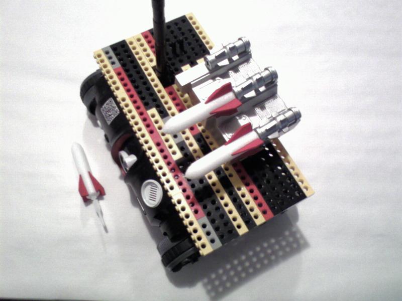
In honor of National Robotics Week and the Instructables Robot Challenge I am submitting a few robot designs. This design (for ages 13-18) takes advantage of Wild Planet's Spy Video Trakr, which is easily programmable and designed by its developers to be hacked.
The Trakr is a remote controlled robot equipped with a microphone and color video camera, speaker, a near infrared LED for night vision, an SD memory card slot for recording audio/video and 8MB of on board memory for storing downloadable and user designed programs. The remote control unit has control levers to drive the robot, a speaker and color video display so you can hear the audio picked up by the microphone and display the video transmitted by the camera, and several function buttons that can be used to control additional program functions of user designed programs.
In this Instructable you will learn how to hack the Spy Video Trakr. You will learn how to download and install the C language compiler for the Trakr. You will learn how to compile a simple program and install it on the Trakr and then run this simple program. Next you will learn how to open up the Trakr, attach jumper pins to the GPIO connections on the main circuit board of the Trakr. You will learn how an electronic relay works, what the electronic scematic diagram for a relay looks like, and what an actual electronic circuit diagram in which the relay is used looks like. You will learn how to make conversion cables to connect the Trakr to external devices. You will learn how to make a larger cargo deck for the Trakr and mount a foam missile launcher platform on the new cargo deck. You will learn how to tap into the Trakr's 9 volt and 5 volt power supplies. Finally you will learn how to write and compile a program to fire missiles from the foam missile launcher and install it on the Trakr and then run the program.
Download and Install the C Language Compiler for the Trakr

What's a compiler? Have you seen those geeky T-shirts that say "there are only 10 types of people in the world: those who understand binary, and those who don't?" If you find yourself scratching your head instead of laughing hysterically, then you don't understand binary. Computers, on the other hand, understand only binary. 1s and 0s. On and off.
I have heard of some people who can do binary code, or machine language in their heads, but the rest of us normal people would have a difficult time writing a computer program out of nothing but 1s and 0s. Instead we use a higher level language like C language to write software.
Have you ever been to a foreign country and didn't know the language? You can hire a translator to translate what you say into the language that the locals can understand. That's what a compiler does. Computers can't understand C language so, a compiler translates the software you write in C language into machine code, or the 1s and 0s that computers can understand.
Download the Compiler Zip File
You'll need to download and install the C language compiler so that you can write programs for the Trakr and compile your software into machine language that the Trakr can understand. The C Language compiler is included in a fairly complete software development kit (SDK) that the folks at Wild Planet call the "Primer." So, download the Primer and save it on your computer where it'll be easy to find by clicking the following link:
http://www.spygear.net/help/files/TRAKR_APP_PRIMER_V1.2.zip
(see pictue 1 above)
Copy the Primer Files to the C:\trakr Folder
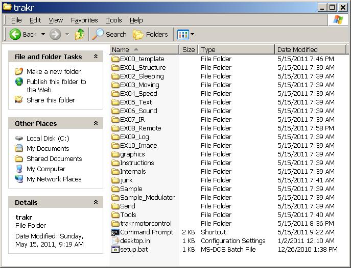
Make a new folder in the root directory of your hard drive (usually the C: drive) called C:\trakr. Then open the Trakr Primer zip file you downloaded from the Trakr web site and copy all the files and folders from the Trakr Primer zip file into your C:\trakr folder. (see picture 2 above)
Update Windows Environment Variables
Next you'll need to update the environment variables to include the path to the Primer's compiler and tools. If you don't know what environment variables are, don't worry, you're just telling your computer where to find the compiler and the tools it needs to compile your Trakr programs.
Open a command prompt, which is a Windows text based interface. Go to Start->Programs->Accessories->Command prompt. You will see a flashing cursor after the ">" and you can type text based commands. When you're done typing a command press the Enter key on your keyboard to execute the command. At the command prompt, type the following commands (see picture 3 above):
cd trakr
setup
cd Internals
Make a Test File to Verify Compiler Installed Correctly
The compiler runs when you type "make" at the command prompt so you need to make sure you navigate to the folder where the makefile you want to run is located. The compiler then follows any instructions in that "makefile" to convert the "app.c" file (the text file containing the source code) into a TRAKR program.
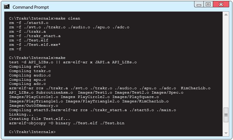
The compiler only looks for the "app.c" file in the current folder so always name your source code app.c. Save your programs in separate folders with names which make sense. This helps to keep all the various "app.c" files organized. As shown in the screen shot, you'll want to run "make clean" in the C:\Trakr\Internals folder. It reports all the files it is removing before returning the prompt to you. Then type "make" at the command prompt and the compiler will use the "makefile" to assemble all the parts of your program (which may include many libraries, images and files specified by your code) into a .bin file to write to the TRAKR hardware. (see picture 4 above)
At the "C:\Trakr\Internals>" prompt type:
make clean
make
Your newly compiled program or app for the Trakr is called "Test.bin" and the file will need to be copied to the Trakr. Make sure the Trakr is switched off and connect it to your computer using the yellow USB cable that came with the Trakr. Copy Test.bin to the APPS folder inside the Trakr folder. Disconnect the Trakr from your computer and switch the Trakr on. Switch the Trakr remote on, click the home button, and select Test from the menu. It's just a little app that tests all the various functions that your Trakr can do such as motor tests, screen functions and so on.
Installing the Jumper Pins on the Trakr's Circuit Board

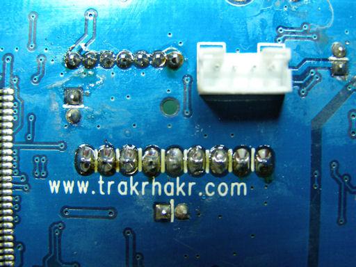
This section will briefly explain how to disassemble the Trakr and install the headers. Please note that this project is not difficult, but it does require some patience.
If you are inexperienced or uncomfortable soldering on a printed circuit board, you can follow the instructions to disassemble the Trakr, and either use Wire Glue (special conductive glue--see picture 1) to glue the header pins to the to Trakr's circuit board or you can take it to someone who can solder it for you.
The GPIOs and the Analog to Digital converter (ADC) are inputs and outputs that can be used to control things. They share a .1" pitch header. The JTAG is a programming/testing port that uses a 2mm header. You'll learn how to install both the GPIO and JTAG headers, but you can just install the GPIO header if you want.
Parts Needed
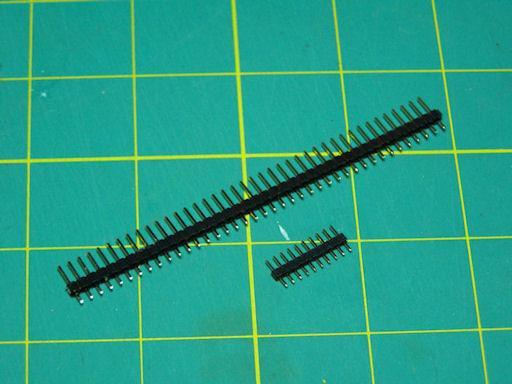
The GPIO header is part # PRT-00116 ($1.50). It is a 40-pin header. Since we only need 9 pins, that one part is enough for 4 Trakrs! (see picture 2)
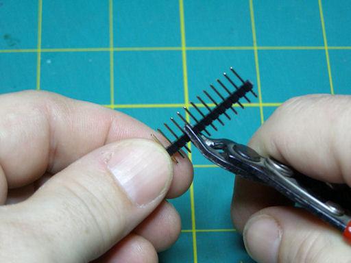
The JTAG header is part # PRT-10112 ($0.95) from Sparkfun http://www.sparkfun.com for the JTAG header. It's 10 pins; we only need 7, so we can just snip off the extras. (see picture 3)
http://www.sparkfun.com/search/results?term=header&what=products
Wire Glue conductive glue can be ordered from ThinkGeek for $3.99
http://www.thinkgeek.com/gadgets/tools/b70c/?srp=1
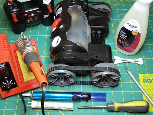
You'll need these additional items for this project (see picture 4):
- Trakr
- #1 Phillips screwdriver
- Fingernail polish remover
- Cotton swabs
- Exacto knife (or similar hobby knife)
- Soldering iron
- Solder
- Vacuum desoldering tool (aka 'solder sucker'...hey, nobody's perfect, and you may have to fix a mistake!)
Remove the White Plastic Cover
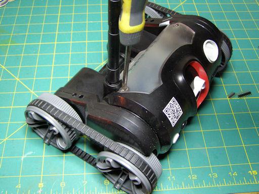
Start by removing the two screws for the back cover. Throughout this project, be mindful of the antenna, and don't break it! (see picture 5)
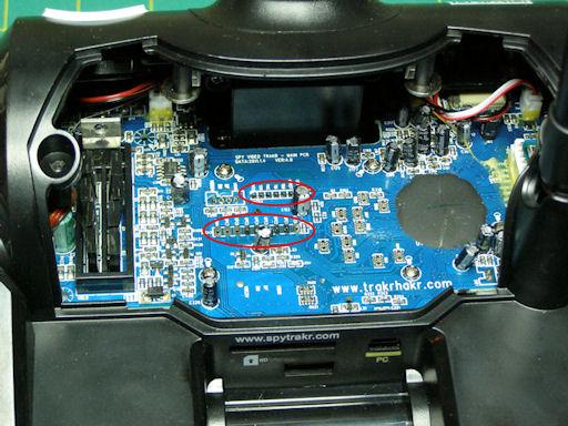
When that's done, you can look in at the mainboard, and see where we're going to install the headers. (see pictute 6) If you have decided to use Wire Glue conductive glue to glue the headers to the Trakr circuit board, you can glue them down now and skip the rest of the Trakr disassembly instructions an go to the next Instructables step.
Remove the Black Plastic Cover
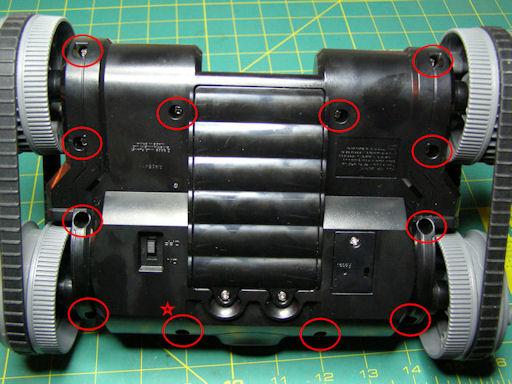
You'll want to fold the antenna over and then flip the Trakr over so you can get at the screws that fasten the Trakr case together. Use a philips screwdriver to remove all the case screws (you can ignore the battery and reset compartment screws). There are a total of 12 screws to remove. Note that the screw marked with a star is shorter than the other 11, so keep track of it. (see picture 7)
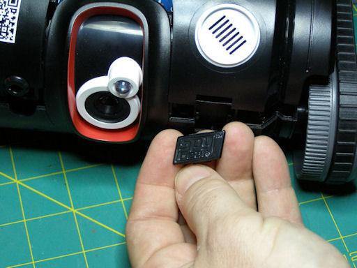
Once the cover screws are removed, you can pull the upper and lower housings apart. When you do, the emblem on the front will fall out. No worries. There's also another piece behind it that will now be loose. Set them both aside, and remember to replace them when reassembling the Trakr. (see picture 8)
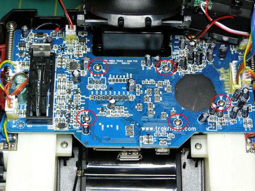
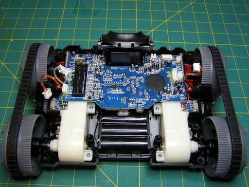
With the upper housing moved aside, you can see the shiny screws holding in the mainboard. Resist the temptation and don't remove them yet! (see picture 9)
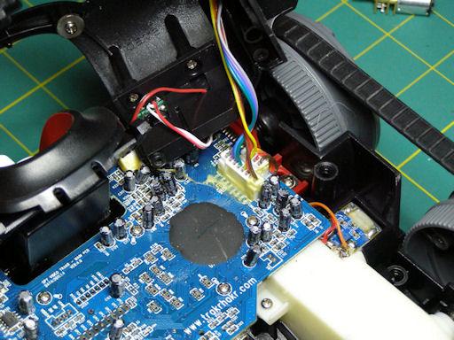
Once the cover screws are removed it's easy to lift the cover enough to see most of the main board. When opening up the cover remember to be careful. There are a number of wires that are connected between the cover and the mainboard. The connectors for the wires are modular, but to make the Trakr more rugged, the connectors have been glued together. I don't know what kind of glue Wild Planet used, but it must be UFO technology from Area 51! It's tough stuff! This is where the fingernail polish remover and patience are employed. (see picture 10)
Dealing With Circuit Board Connector Glue
With a cotton swab, apply fingernail polish remover to the glue to soften it up. It will probably take more than one application. Allow the polish remover time to soak into the glue. Use the hobby knife to trace along the connector joints, and to peel the glue away from the connectors. Note that the connectors also have two tabs molded into the plastic so they'll latch together. I used the knife to release the tabs, once the glue was cleaned away. (see picture 11)
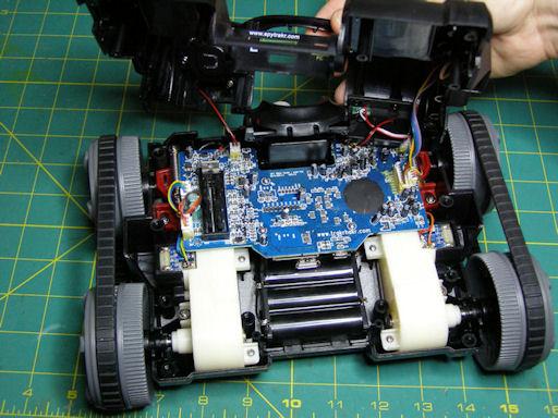
With the connectors unglued and separated, you can now set aside the upper housing (see picture 12). If while trying to separate the connectors, you end up pulling the whole thing off the board, don't fret. The pins on the board will still be okay. If you look at picture 12, you'll notice that I accidentally pulled the whole connector for the speaker off of the left front leaving the pins sticking up from the board. It was easy to reattach the connectors to the naked pins once I got the connector separated. It is easy to reconnect the connector to the pins and they will hold quite snugly, but if you want you can use a hot glue gun to reattach it to the circuit board. Keep in mind that the connectors for the push button and the speaker are non-polar meanining it won't matter which way you reattach the connectors to the pins. On the other hand, the microphone connector needs to be reconnected exactly the same way it was accidently disconnected because it is a polar connector. It has a plus side and a minus side and if you reconnect it the wrong way you won't be able to hear anything from the microphone and it could burn out the microphone.
Camera Ribbon Cable
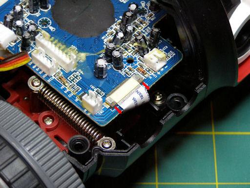
Before you take the main circuit board screws out, there's another connector to unhook. This flat white ribbon cable is on the right front of the Trakr, and is for the camera assembly. It's a pressure-type connector that holds the ribbon cable against the contacts of the socket. To release, slide the little brown tabs (they're actually connected and run underneath the ribbon cable) forward about 1/8" and the cable will slide right out. (see picture 13)
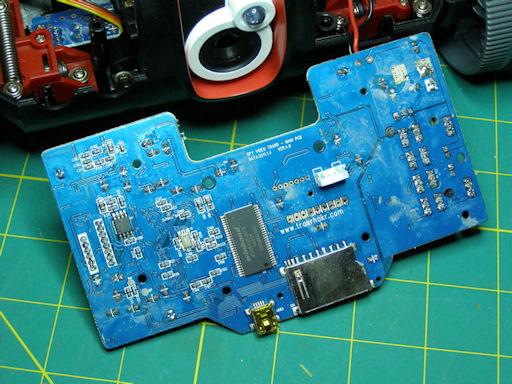
Remove the five main circuit board screws, and unhook the connector to the USB port from the bottom. I left the power leads from the battery pack soldered on, since I had enough freedom of movement even with them connected. (see picture 14)
Solder the Headers
At this point, it's a simple matter to insert the headers into the holes on the mainboard, and solder them in. Good solder joints are smooth and shiny like these (see picture 15). Ensure that none of them are soldered to their neighbor (solder bridge).
Now reverse the disassembly process to put your Trakr back together!
Keep It Simple Stupid

The voltage output directly from the GPIO pins is only 3.3 volts so, there aren’t many devices other than LEDs that you can drive with such low voltage. If you wanted to control, say, a Lego motor that runs on nine volts, you would need a nine volt voltage source yet prevent accidently sending nine volts through the Trakr’s processor and frying it.
When deciding what kind of circuit to connect to the GPIO pins, always apply the maxim, “Keep It Simple, Stupid” (KISS). If, for example, you wanted to drive a single motor in only one direction, the simplest device to keep a higher voltage source–the one used to drive a motor–from accidently passing through the Trakr’s processor is an electronic relay.
Electronic Relay
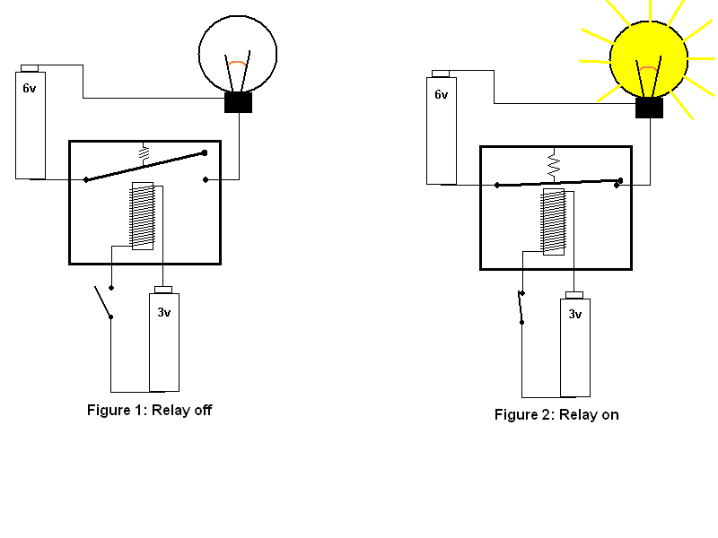
What’s a relay? You’ve probably seen a relay race where one runner hands off a baton to another runner. Similarly, an electronic relay hands off control from one circuit to another. A relay is a very simple device consisting of an electromagnet, an armature (a switch that closes when attracted by the electromagnet), and a spring that is connected to the armature. You can see in the diagrams (Source: How Stuff Works) how the relay works.
In Figure 1 of the diagram (see picture 1), there are two circuits. The first circuit is a battery (3 volts), a switch and an electromagnet. The second circuit is a battery (6 volts), a light bulb and the relay’s armature. While the switch to the electromagnet is off, no current can flow from the 3 volt battery through the electromagnet. So, the armature-switch is off and no current can flow from the 6 volt battery to power the lamp in the second circuit.
In Figure 2 the switch to the electromagnet circuit is switched on. When current from the 3 volt battery flows through the electromagnet, the electromagnet creates a magnetic field that attracts the armature to close the circuit to the lamp. Now current can flow from the 6 volt battery to the lamp, and the lamp lights up.
If you look closely at Figure 2, you’ll notice that while the armature-switch is closed allowing the current in the lamp circuit to flow from the 6 volt battery to the lamp, it does not come into contact with the electromagnet so, the 6 volts from the lamp circuit cannot flow into the electromagnet circuit. Thus, the 3 volts in the electromagnet circuit and the 6 volts in the lamp circuit remain separate.
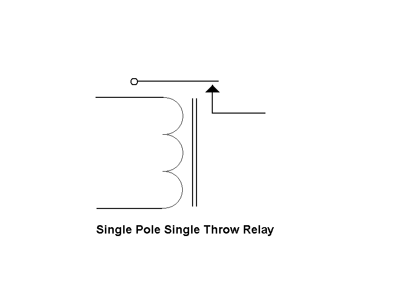
Picture 2 is the electronic schematic diagram of a relay. The curly line represents the electromagnetic coil and the vertical lines represent the metal core the coil is wrapped around. The switch at the top of the diagram represents the armature.
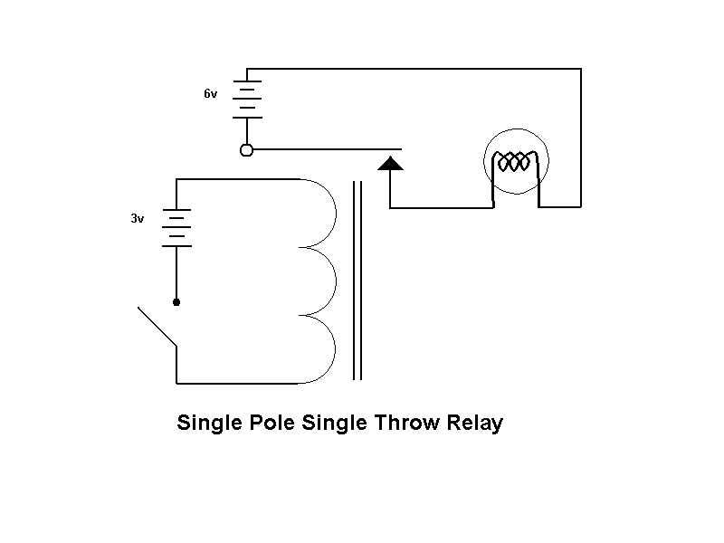
Picture 3 is the electronic schematic of the circuits from figures 1 and 2.
Since the Spy Video Trakr is a toy recommended for ages eight and older, this Instructable is designed for kids to try. Where ever possible I’ve tried to use alternatives to soldering and hot glue (Note: Wire Glue conducting glue is recommeneded for ages 10 and older and young kids should use it with the supervision of an adult) . Among the solderless alternatives selected for this Instructable are Snap Circuits.
Snap Circuits: A Solderless Alternative
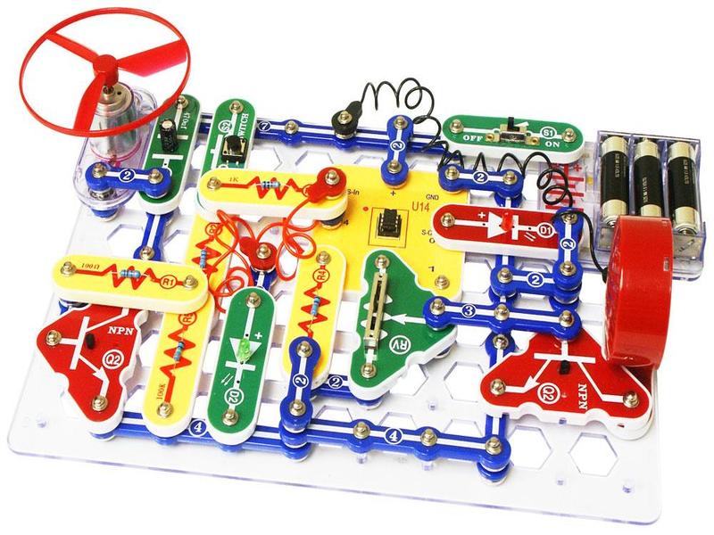
Snap Circuits by Elenco is an educational toy that teaches folks about electronics with solderless snap-together electronic components (see picture 4). Each electronic component has the electronic schematic symbol and a label printed onto its plastic case that is color coded for easy identification. They snap together with what appear to be ordinary clothing snaps—hence the name Snap Circuits. The components also snap onto a 10 X 7 plastic base grid, which is analogous to a solderless breadboard.
There are several Snap Circuits kits that range from a few simple circuits to the largest kit that includes 750 electronic projects. All the kits include manuals printed in color with easy to follow diagrams to assemble the projects. The illustrations for each project look almost exactly like what the components will look on the base grid when finished. Because the electronic symbol is printed on each electronic component, once the project is completed, it will look almost exactly like a printed electronic schematic. (see picture 4)
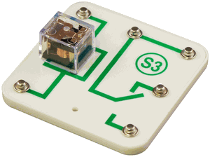
Picture 5 is what a snap circuits relay looks like. To connect the relay to non-snap circuits parts like the header pins on the Spy Video Trakr you have to make conversion cables. You can cut a Snap Circuits jumper wire (see picture 6) in half and connect the halves to other kinds of cables.
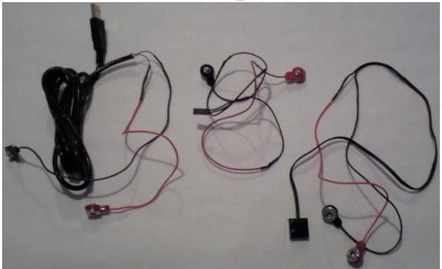
In picture 7, you'll see three Snap circuits conversion cables that I have made. The cable on the left is a USB to Snap Circuits cable so that I can power motors and other devices up to five volts. The center cable is a header pin to Snap Circuits cable so that I can connect a Snap Circuits block directly to the GPIO header pins on the Trakr's circuit board. The cable on the right is a Snap Circuits to Lego cable so I can connect a Snap Circuits block to a Lego motor. They were easy to make.
I simply cut Snap Circuits jumper wires in half, removed about 1/2 inch of insulation from the jumper wire and the wires I wanted to connect them to, twisted the wires together, and covered them with shrink tubing to prevent short circuits from the exposed wire. These are temporary for now but can be made permanent with Wire Glue conductive glue.
Add a Common Ground for Your Projects
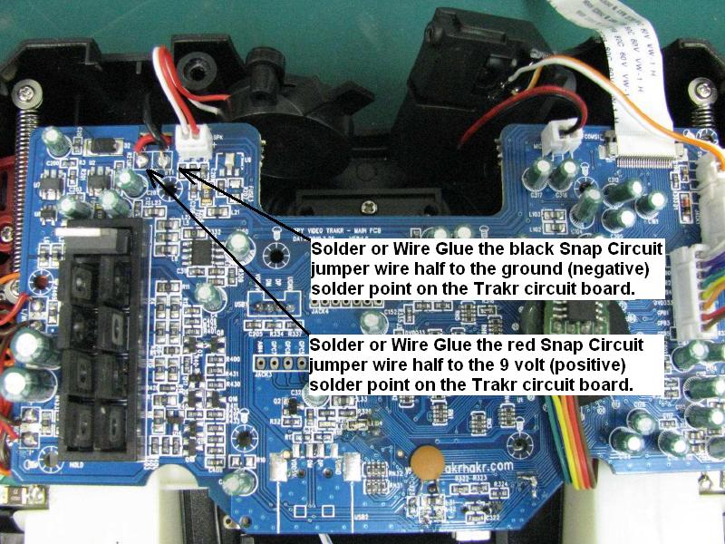
You'll probably want to add a common ground for your projects. Since you'll have the Trakr opened up anyway, might as well add a 9 volt power tap the the positive solder point on the Trakr. Use the same process as making Snap Circuits conversion cables. I had a red Snap Circuit jumper wire half and a black Snap Circuit jumper wire half left over.
You can solder or Wire Glue the black Snap Circuit jumper wire half to the ground or negative solder point on the Trakr's circuit board. It is where the black wire from the battery pack is soldered to the Trakr's circuit board.
You can solder or Wire Glue the red Snap Circuit jumper wire half to the 9 volt or positive solder point on the Trakr's circuit board. It is where the red wire from the battery pack is soldered to the Trakr's circuit board.
A Versatile Cargo Deck
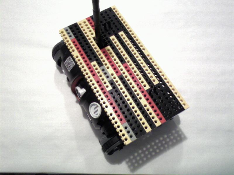
Next you'll want to design a way of mounting the devices you want to control on to the Trakr. The deck in picture 1 was made from Lego technic beams.
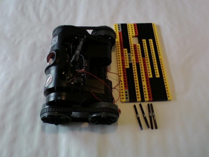
Picuture 2 is the Lego Deck disassembled. I discovered that Lego cross axles fit snugly into the the mounting holes for the plastic deck that came with the Trakr.
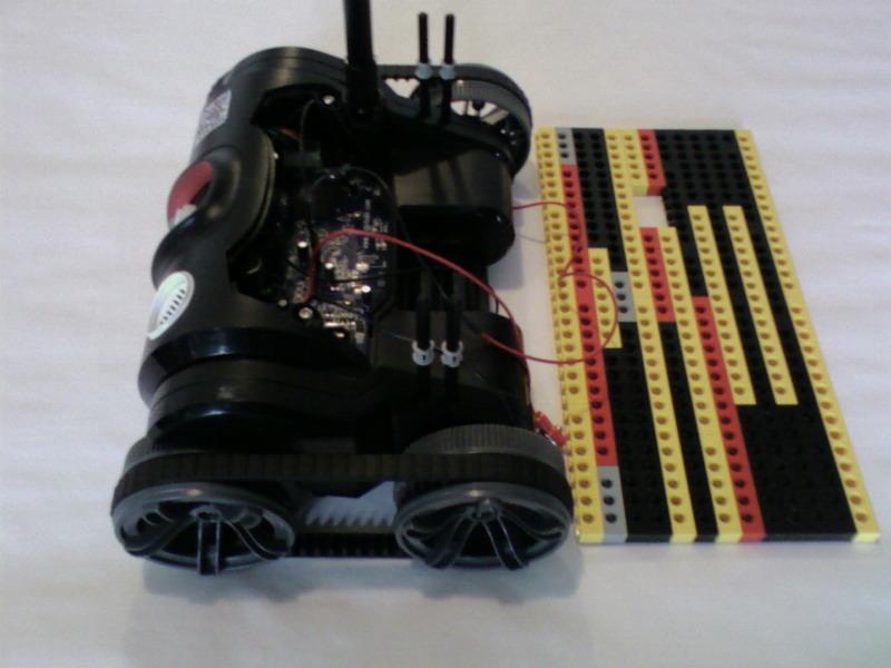
Picture 3 shows the Lego cross axles inserted into the mounting holes for the plastic payload deck that came with the Trakr. I find that the holes in the Lego Technic beams are very versitile and allow me to mount many kinds of external devices.
Design the Circuit
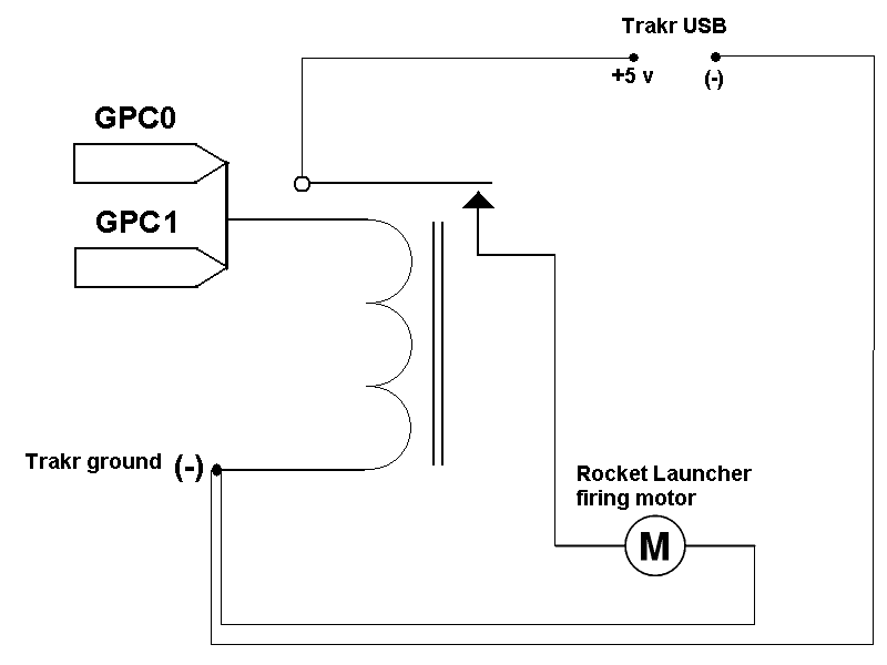
Once you've decided on what external device you want to control and how to mount it on the Trakr, you are ready to begin designing the circuit. (see picture 1)
In this example, I'm using the missile platform from a USB laser guided missle launcher.
In the platform there is a single motor that turns in one dirction to rotate a cam shaft that launches all three missiles in one after the other.
Since I only have to drive one motor in one direction, I can use an electronic relay.
Now that a common ground is avaialble, at least two power sources are available from the Trakr: the 9 volts from the Trakr's battery pack and five volts from the USB. The USB missile launcher only requires 5 volts so, I can use my USB to Snap Circuit adapter cable to power the rocket launcher motor.
The Snap Circuit relay will power on at 3 volts as you can see in the following video:
http://player.vimeo.com/video/33376632
Often when using electronic relays in circuits it is recommended that you insert a flyback diode to protect sensitive electronics. The magnetic coil in the relay stores electricity like a capacitor and when the voltage is cut from the coil the current can flow back into the circuit--back to the GPIO pins. I've built this simple circuit to demonstrate what I mean. You may have to wait a moment for me to dim the lights a bit to see the led flash, but when I push the button, this engages the electromagnet in the relay and you may be able to hear the relay click on. When I release the button this cuts off the voltage to the relay (you may be able to hear it click off) and the magnetic field collapses and the current flows back into the circuit causing the LED to flash.
http://player.vimeo.com/video/32551898
Fortunately the voltage is so low you will not need to insert a flyback diode.
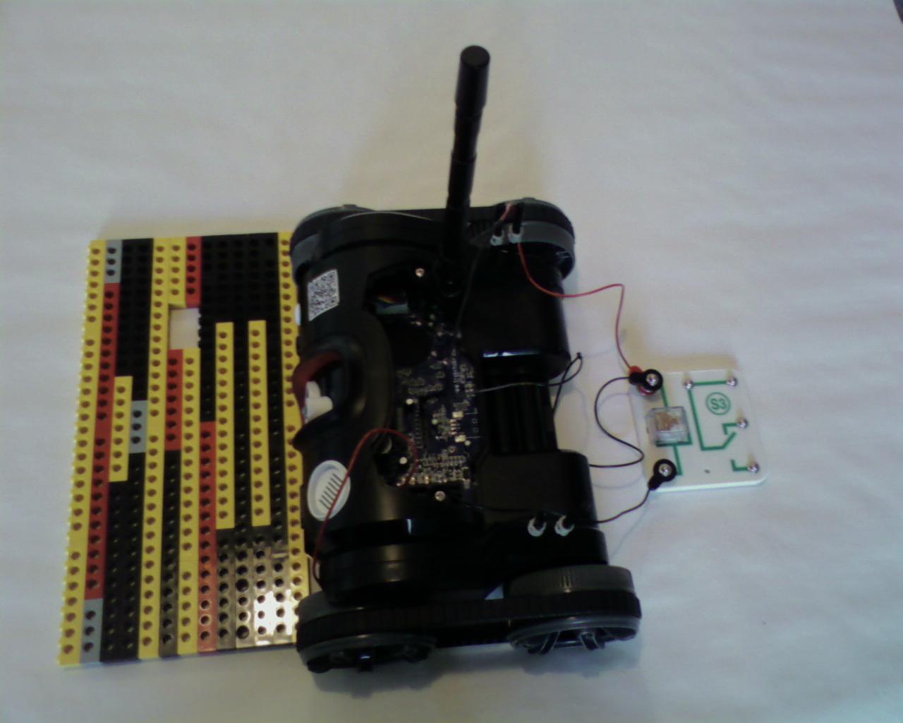
For some reason, however, there just isn't enough current from one GPIO line to get the relay's armature to close so, we have to add two GPIO lines. This is definitely a kludge, yet nontheless will demonstrate how to use a relay with the Trakr. In the schematic you will see that there are two GPIO lines connected to the positive side of the relay coil. I used the GPIO to Snap Circuit conversion cable that I made. The negative side is connected to the Trakr's negative or ground using the black Snap Circuit jumper wire half that is soldered/Wire Glued to the Trakr's circuit board. Those are all the connections on the Trakr side of the relay.
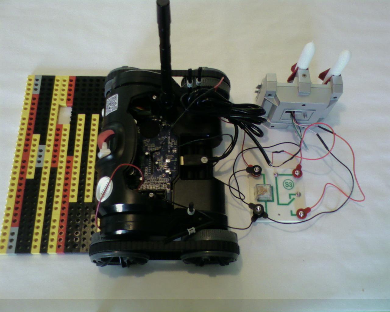
On the missile launcher side, 5 volts from the USB is connected to the relay's switch. I used the USB to Snap Circuit conversion cable that I made. The negative cable from the USB is connected to the Trakr's ground or negative black Snap Circuit jumper wire half. The positive side of the rocket launcher motor is connected to the relay's switch and the negative side of the rocket launcher motor is connected to the Trakr's ground or negative black Snap Circuit jumper wire half.
Connect the Relay to the Trakr
Picture 2 is the Trakr side of the relay with the two GPIO lines connected to the positive side of the relay coil. I used the GPIO to Snap Circuit conversion cable that I made. The negative side is connected to the Trakr's negative or ground using the black Snap Circuit jumper wire half that is soldered/Wire Glued to the Trakr's circuit board.
Connect the Missile Launcher to the Relay
Picture 3 is the missile launcher connected to the relay. 5 volts from the Trakr's USB port is connected to the relay's switch. I used the USB to Snap Circuit conversion cable that I made. The negative cable from the USB is connected to the Trakr's ground or negative black Snap Circuit jumper wire half. The positive side of the rocket launcher motor is connect the the relay's switch and the negative side of the rocket launcher motor is connected to the Trakr's ground or negative black Snap Circuit jumper wire half.
Program the Trakr

Below is the C Langusage source for the Trakr App:
////////////////////////////////////////////
//relaycontrol app for Spy Video TRAKR.
//Program scans to see if button A was
//pressed on TRAKR remote and sets GPC0 high
//and GPC1 high to send current through
//a relay's electromagnetic coil. This will
//activate the relay's switch closing the
//circuit of an external device.
///////////////////////////////////////////
#include "svt.h" //include Official API
#include "JAPI.h" //include "Secret sauce" API
#define GPC0 (1<<0) //bitmask for pin GPC0 = 00000001
#define GPC1 (1<<1) //bitmask for pin GPC1 = 00000010
#define GPC2 (1<<2) //bitmask for pin GPC2 = 00000100
#define GPC3 (1<<3) //bitmask for pin GPC3 = 00001000
#define GPC4 (1<<4) //bitmask for pin GPC4 = 00010000
#define GPC5 (1<<5) //bitmask for pin GPC5 = 00100000
#define GPC6 (1<<6) //bitmask for pin GPC6 = 01000000
#define GPC7 (1<<7) //bitmask for pin GPC7 = 10000000
int keyState; //define "keystate" as integer
void Start()
{
JAPI_SetIoOutputMode(GPC0+GPC1);//Set output mode for pins GPC0 and GPC1
}
bool Run()
{
keyState=GetRemoteKeys(); //TRAKR remote control key pressed
//assign to keystate
if (keyState > 0)
{ //if keystate is greater than 0
if(keyState&KEY_INPUT1)
{ //Button A pressed
JAPI_SetIoHigh(GPC0+GPC1);//Set GPC0 and GPC1 pins high (3.3v)
} else {
JAPI_SetIoLow(GPC0+GPC1); //Switch off pins GPC0 and GPC1
}
if(keyState&KEY_HOME)
{ //if Home button pressed
return false; //this will end the loop
}
}
return true; //loop will repeat until false
}
void End()
{ //Program end - switch off both pins
JAPI_SetIoLow(GPC0+GPC1);
}
And next is the Make file:
# Makefile for TRAKR Toy
# Trakr Project
TRACKR_PATH = C:/Trackr
PROGRAM_NAME = relaycontrol
PRETTY_NAME = relaycontrol
OUTPUT_PATH = ./Intermediate
OUTPUT_NAME = $(OUTPUT_PATH)/$(PROGRAM_NAME).elf
INTERNALS_PATH = ../Internals
SOURCES = app.c
S_OBJECTS = $(OUTPUT_PATH)/app.o
OBJECTS = $(S_OBJECTS) $(INTERNALS_PATH)/trakr.a
SHELL = sh
CC = arm-elf-gcc
AS = arm-elf-as
BIN = arm-elf-ld
LD = arm-elf-ld
TOPMEMORY=0xFFE7C000
CFLAGS = -O0 -I../Internals/Include -I../Internals -Wall -gstabs+
TARGET_FLAG = -mcpu=arm926ejs -mapcs-32 -mlittle-endian -specs=specs.semi
LDFLAGS = -T ../Internals/WJ_APP_8M.ld -Wl,--defsym -Wl,__stack_base=$(TOPMEMORY) -Wl,-Map -Wl,$(basename $@).map -nostartfiles -static
all: prebuild $(OUTPUT_NAME) postbuild
$(OUTPUT_NAME): $(OBJECTS)
@echo "Linking... "
@echo "Creating file $@..."
@$(CC) -u _start -o $@ $(INTERNALS_PATH)/trakr_start.a $(OBJECTS) $(TARGET_FLAG) $(LDFLAGS)
$(OUTPUT_PATH)/app.o:app.c Makefile
@echo "Compiling $<"
@$(CC) -c -o "$@" "$<" $(TARGET_FLAG) $(CFLAGS)
.PHONY: clean prebuild postbuild
clean:
$(RM) -f $(PROGRAM_NAME).bin
$(RM) -f "$(PRETTY_NAME).bin"
$(RM) -f $(OUTPUT_PATH)/app.o
$(RM) -f $(OUTPUT_NAME)
$(RM) -f $(MKDEPFILE)
postbuild:
arm-elf-objcopy -O binary $(OUTPUT_NAME) "$(PRETTY_NAME).bin"
@if [ -d "E:/" ] ; then \
cp "$(PRETTY_NAME).bin" e:/APPS/ ; \
fi
prebuild:
# End of Makefile
Make sure the Trakr is switched off and connect it to your computer using the yellow USB cable that came with the Trakr. Copy relaycontrol.bin to the APPS folder inside the Trakr folder. Disconnect the Trakr from your computer and switch the Trakr on. Switch the Trakr remote on, click the home button, and select relaycontrol from the menu. Use the Trakr's remote contol to drive the Trakr to a taget. Aim the Trakr's camera directly at the target and press button A on the remote control to fire foam darts at the target.
Congratulations! In this Instructable you learned how to hack the Spy Video Trakr. You learned how to download and install the C language compiler for the Trakr. You learned how to compile a simple program and install it on the Trakr and then run this simple program. Next you learned how to open up the Trakr, attach jumper pins to the GPIO connections on the main circuit board of the Trakr. You learned how an electronic relay works, what the electronic scematic diagram for a relay looks like, and what an actual electronic circuit diagram in which the relay is used looks like. You learned how to make conversion cables to connect the Trakr to external devices. You learned how to make a larger cargo deck for the Trakr and mount a foam missile launcher platform on the Lego cargo deck. You learned how to tap into the Trakr's 9 volt and 5 volt power supplies. You also learned how to use the electronic relay to control a foam dart missile launcher. Finally you learned how to write and compile a program to fire missiles from the foam missile launcher and install it on the Trakr and then run the program.