Read Electricity and Gas Meter (Belgian/Dutch) and Upload to Thingspeak
by pkoerber in Circuits > Microcontrollers
5155 Views, 11 Favorites, 0 Comments
Read Electricity and Gas Meter (Belgian/Dutch) and Upload to Thingspeak


If you are concerned about your energy consumption or just a bit of a nerd, you probably want to see the data from your fancy new digital meter on your smartphone.
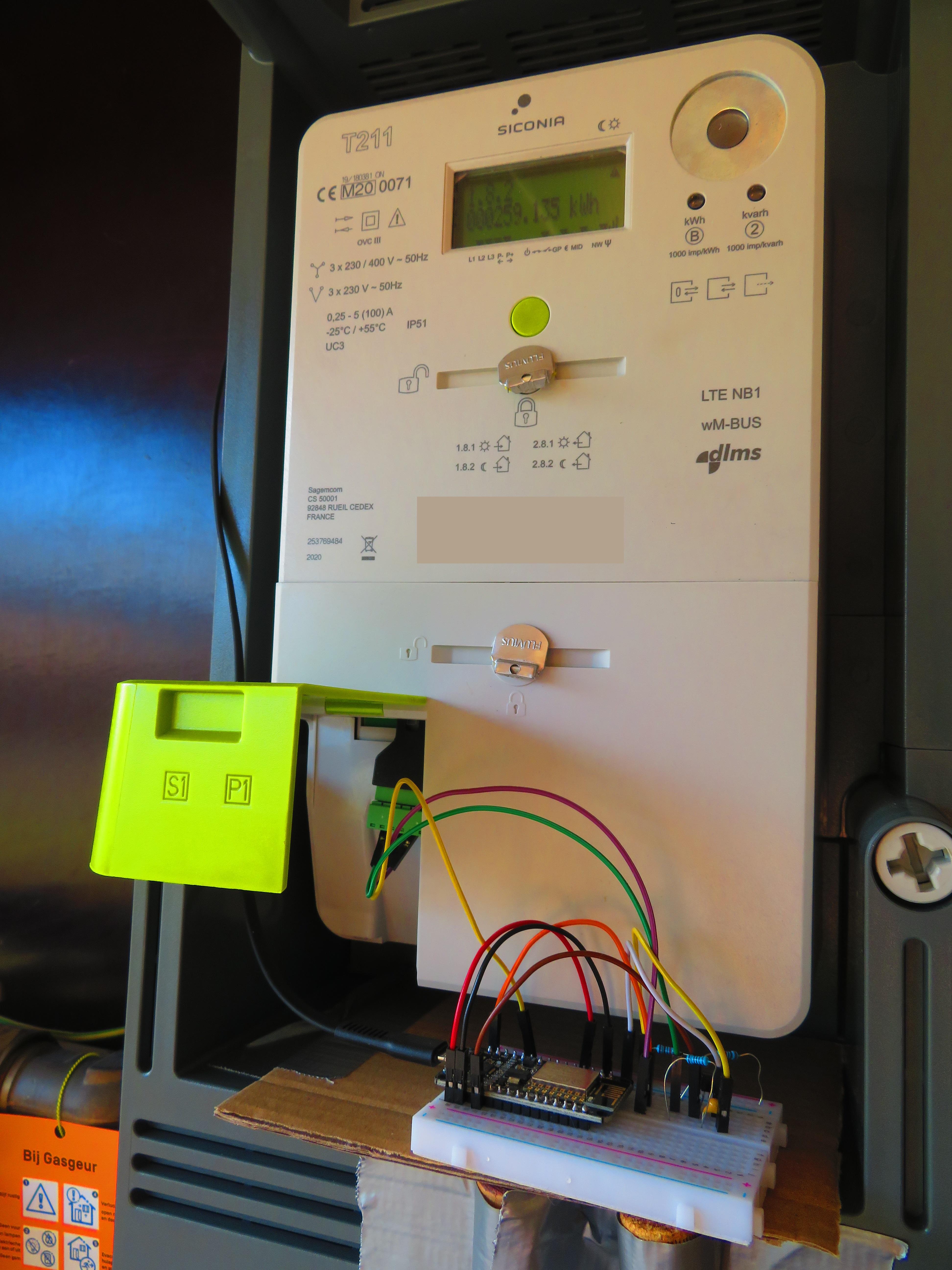
In this project we will obtain the current data from a Belgian or Dutch digital electricity and gas meter and upload it to Thingspeak. This data includes the current and daily power consumption and injection (if you have solar panels), voltages and currents, and the gas consumption (if a digital gas meter is connected to the electricity meter). Through an app these values can then be read off in real time on your smartphone.
It works for a Belgian or Dutch digital meter that follows the DSMR (Dutch Smart Meter Requirements) protocol, which should be all recent meters. If you live somewhere else, unfortunately, your meter will likely use another protocol. So I'm afraid this Instructable is a bit regionally restricted.
We will use the P1-port of the meter, which accepts a RJ11/RJ12 cable, colloquially known as a telephone cable. Make sure the installer of the meter activated the P1 port. For instance, for Fluvius in Belgium follow these instructions.
To process the data and upload to the internet, we use an ESP8266, which is a cheap microchip with built-in wifi. It only costs something like 2 dollar. Moreover it can be programmed using the Arduino IDE. We store the data in the cloud on Thingspeak, which is free for a maximum of four channels. For this project we only use one channel. The data can then be displayed on your smartphone using a app like IoT ThingSpeak.
Parts:
- One ESP8266, like a nodemcu v2. Note that the nodemcu v3 is too wide for a standard breadboard, so I prefer the v2.
- A micro USB to USB cable.
- A USB charger.
- One BC547b NPN transistor.
- Two 10k resistors and one 1k resistor.
- One RJ12 screw terminal connector.
- A breadboard.
- Jumper wires.
- Optional: one 1nF capacitor.
In total, this costs something like 15 EUR on AliExpress or similar. The estimate takes into account that some components like the resistors, transistors and wires, come in much larger quantities than you need for this project. So if you already have a component kit it'll be cheaper.
Getting to Know the ESP8266
I chose the NodeMCU v2, since no soldering is required and it has a micro USB connection that allows for easy programming. The advantage of the NodeMCU v2 over the NodeMCU v3 is that it is small enough to fit on a breadboard and leave free holes at the side to make connections. So it's better to avoid the NodeMCU v3. However, if you prefer another ESP8266 board that is also fine.
The ESP8266 can be easily programmed using the Arduino IDE. There are other Instructables explaining this in detail so I'll be very brief here.
- First download the Arduino IDE.
- Second install support for the ESP8266 board. In the menu File - Preferences - Settings add the URL http://arduino.esp8266.com/stable/package_esp8266com_index.json to Additional Board Manager URLs. Next in the menu Tools - Board - Boards Manager install esp8266 by esp8266 community.
- Third select the board closest to your ESP8266. In my case I chose NodeMCU v1.0 (ESP 12-E Module).
- Finally select under Tools - Flash Size, a size that includes SPIFFS, like 4M (1M SPIFFS). In this project we use the SPIFFS (SPI Flash File System) to store daily energy values, so that they are not lost if the ESP8266 loses power and even when it is reprogrammed.
Now we have everything in place to program the ESP8266! We'll discuss the actual code in a later step. First we'll make a Thingspeak account.
Create a Thingspeak Account and Channel
Go to https://thingspeak.com/ and create an account. Once you are logged in click the button New Channel to create a channel. In the Channel Settings fill in the name and description as you like. Next we name the channel fields and activate them by clicking the checkboxes to the right. If you use my code unchanged the fields are as follows:
- Field 1: peak consumption today (kWh)
- Field 2: off-peak consumption today (kWh)
- Field 3: peak injection today (kWh)
- Field 4: off-peak injection today (kWh)
- Field 5: current consumption (W)
- Field 6: current injection (W)
- Field 7: gas consumption today (m3)
Here, peak and off-peak refer to the electricity tariff. In fields 1 and 2 consumption refers to net electricity consumption today: consumption of electricity today in the tariff period since midnight minus injection of electricity (produced by solar panels) today in the tariff period since midnight with a minimum of zero. The latter means that if there was more injection than consumption today the value is zero. Likewise, injection in fields 3 and 4 refers to net injection of electricity. Field 5 and 6 indicate net consumption and injection at the current moment. Finally field 7 is the gas consumption since midnight.
For future reference write down the Channel ID, the Read API Key and the Write API Key, which can be found in the menu API keys.
Building the Electronic Circuit


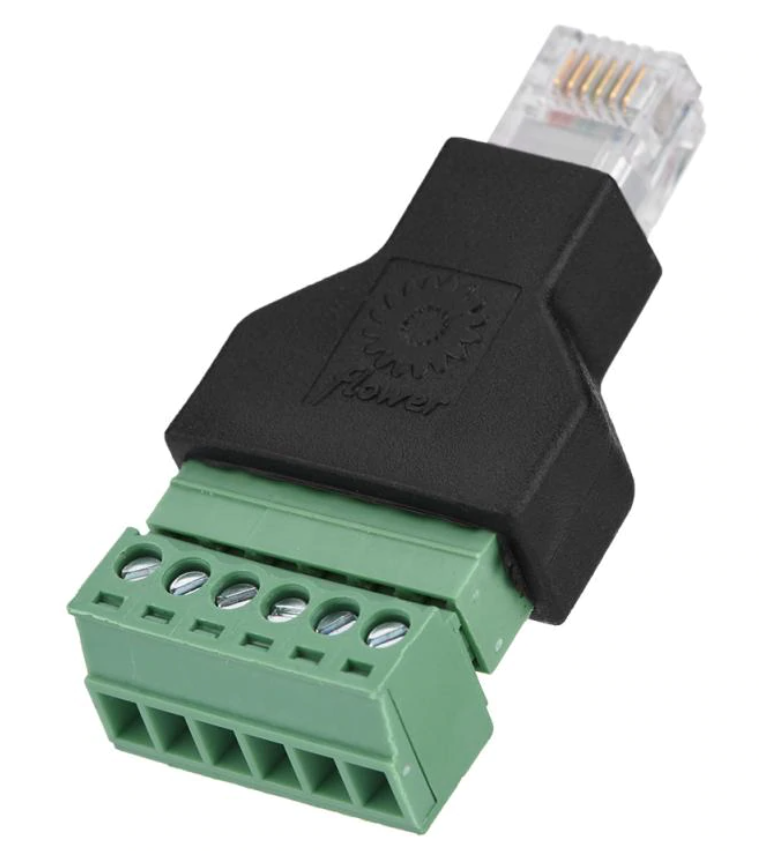
We read off the electricity meter using the P1 port, which takes a RJ11 or RJ12 cable. The difference is that the RJ12 cable has 6 wires while the RJ11 has only 4. In this project we don't power the ESP8266 from the P1 port so we actually only need 4 wires, so a RJ11 would do.
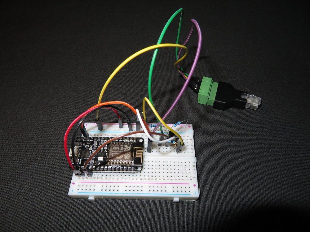
I used the RJ12 breakout shown in the picture. It is a bit wide and there is not much space around the P1 port in my meter. It fits, but it is tight. Alternatively, you could just use a RJ11 or RJ12 cable and strip off the header at one end.
If you hold the break-out as in the picture, the pins are numbered from right to left and have the following meaning:
- Pin 1: 5V Power supply
- Pin 2: Data Request
- Pin 3: Data Ground
- Pin 4: not connected
- Pin 5: Data line
- Pin 6: Power ground
Pin 1 and Pin 6 could be used to power the ESP8266, but I haven't tested this. You would have to connect Pin 1 to Vin of the ESP8266, so the internal voltage regulator of the board is used to reduce the voltage from 5V to the 3.3V that the ESP8266 accepts. So don't connect it to the 3.3V pin, because that might damage the ESP8266. Also powering from the P1 port would over time drain the battery of the digital meter.
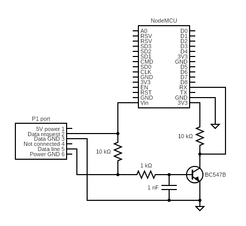
Setting pin 2 high signals the meter to send data telegrams every second. The actual data is send over Pin 5 with a baud rate of 115200 for a modern digital meter (DSMR 4 and 5). The signal is reversed (low is 1 and high is 0). For an older type (DSMR 3 and below) the rate is 9600 baud. For such a meter you have to change the baud rate in the firmware code of the next step: change the line Serial.begin(115200); in setup().
The role of the NPN transistor is two-fold:
- To reverse the signal so the ESP8266 can understand it.
- To change the logic level from the 5V of the P1-port to the 3.3V expected by the RX port of the ESP8266.
So create the electronic circuit on the breadboard as in the diagram. The capacitor increases the stability, but it also works without.
Hold off connecting the RX pin until you have programmed the ESP8266 in the next step. Indeed, the RX pin is also needed to communicate over the USB between the ESP8266 and your computer.
Upload the Code
I have made the code available on GitHub, it's just one file: P1-Meter-Reader.ino. Just download it and open it in the Arduino IDE. Or you can select File - New and just copy/paste the code.
There is some info you have to fill in the beginning of the file: the name and password of the WLAN to use, and the Channel ID and Write API Key of the ThingSpeak Channel.
The code does the following:
- Reads a data telegram from the meter every UPDATE_INTERVAL (in milliseconds). The default value is every 10 seconds. Normally, there is a data telegram from the meter every second, but setting the frequency to high will overload the ESP8266 so it cannot run the webserver anymore.
- Uploads the electricity data to the Thingspeak channel every SEND_INTERVAL (in milliseconds). The default value is every minute. To decide about this frequency take into account that sending the data takes some time (typically a few seconds) and that there is a limit to the update frequency on Thingspeak for a free account. It is about 8200 messages per day so the maximal frequency would be about once every 10 seconds if you do not use Thingspeak for anything else.
- Uploads the gas data when it changes. Typically, the meter updates the gas consumption data only every 4 minutes or so.
- The meter keeps track of the total consumption and injection values since the start. So to obtain the daily consumption and injection, the code saves the total values at midnight every day. Then these values are subtracted from the current total values. The values at midnight are stored in the SPIFFS (SPI Flash File System), which persists if the ESP8266 loses power or even when it is reprogrammed.
- The ESP8266 runs a mini webserver. If you open its IP address in your browser, you get an overview of all current electricity and gas values. These are from the most recent telegram and include info that is not uploaded to Thingspeak, like voltages and currents per phase. The default setting is that the IP address is dynamically determined by your router. But it is more convenient to use a static IP address, which is always the same. In this case you have to fill in staticIP, gateway, dns and subnet in the code and uncomment the line WiFi.config(staticIP, dns, gateway, subnet); in the function connectWifi().
After you made these changes, you are ready to upload the firmware to the ESP8266. Connect the ESP8266 through the USB cable to your computer and press the icon with the arrow in the Arduino IDE. If you don't manage to connect to the ESP8266 try changing the COM port under the menu Tools - Port. If it still doesn't work it is possible you have to manually install the driver for the USB virtual COM port.
Testing
After uploading the firmware, unplug the USB and connect the RX wire of the ESP8266. Remember, we needed the RX channel of the ESP8266 for uploading the firmware so we didn't connect it before. Now plug in the RJ12 breakout in the digital meter and reconnect the ESP8266 to your computer.
In the Arduino IDE, open the Serial Monitor through the Tools menu and make sure it is set to 115200 baud. If you have to change the baud rate, perhaps you need to close and re-open the Serial Monitor again before it works.
Now you should see the output of the code in the Serial Monitor. You should check whether there are any error messages. Also, you should be able to see the telegrams. For me they look like this:
/FLU5\xxxxxxxxx_x

0-0:96.1.4(50213)
0-0:96.1.1(3153414733313030313434363235)   // Serial number meter hexadecimal
0-0:1.0.0(200831181442S)  // Timestamp S: daylight savings (summer), W: no daylight savings (winter)
1-0:1.8.1(000016.308*kWh)  // Total peak net consumption
1-0:1.8.2(000029.666*kWh)  // Total off-peak net consumption
1-0:2.8.1(000138.634*kWh)  // Total peak net injection
1-0:2.8.2(000042.415*kWh)  // Total off-peak net injection
0-0:96.14.0(0001) // Tariff 1: peak, 2: off-peak
1-0:1.7.0(00.000*kW)  // Current consumption
1-0:2.7.0(00.553*kW)  // Current injection
1-0:32.7.0(235.8*V)   // Phase 1 voltage
1-0:52.7.0(237.0*V)   // Phase 2 voltage
1-0:72.7.0(237.8*V)   // Phase 3 voltage
1-0:31.7.0(001*A)     // Phase 1 current
1-0:51.7.0(000*A)     // Phase 2 current
1-0:71.7.0(004*A)     // Phase 3 current
0-0:96.3.10(1)
0-0:17.0.0(999.9*kW)  // Max power
1-0:31.4.0(999*A)     // Max current
0-0:96.13.0()         // Message
0-1:24.1.0(003)       // other devices on M-bus
0-1:96.1.1(37464C4F32313230313037393338) // Serial number gas meter hexadecimal
0-1:24.4.0(1)
0-1:24.2.3(200831181002S)(00005.615*m3)  // Gas timestamp total consumption
!E461     // CRC16 checksum
If there is something wrong, you can check whether you have the same tags and you possibly have to change the code parsing the telegrams in the function readTelegram.
If everything works you can now power the esp8266 from the USB charger.
Install the IoT ThingSpeak Monitor app on your smartphone, fill in the Channel ID and Read API Key and your done!