RatPack : Wearable Technology for the African Giant Pouched Rat
2639 Views, 4 Favorites, 0 Comments
RatPack : Wearable Technology for the African Giant Pouched Rat


RatPack
The P.Black Oomvelt RatPack is a wearable technology created for the giant African pouched rat to help them communicate to their human handlers when they find a landmine or object of interest. Additionally, the RatPack was made to be of service in the training of the rats and their potential uses in scouting new areas.
The RatPack functions through the use of an accelerometer embedded in a vest that the animals wear. The accelerometer monitors the animal's body motion. Changes in the animal's body motion are monitored in real-time by an embedded machine learning processor that detects when the animal makes certain gestures it has previously been trained to make in response to detecting a scent or object. These gestures are communicated to a person in real time through a webpage. This process is conceptually similar to how a smartwatch can detect if a person is walking or jogging by the motion of the wrist.
The RatPack also has an onboard camera that lets a rat broadcast live video from its environment. The video functionality also greatly assists in the training of the machine learning algorithms that enable the rats to better communicate with people.
Purpose
The purpose of this tutorial is to share the design and creation of the RatPack (in both hardware and software) with the community so that whoever is interested in replicating or adapting the device can benefit from it. If you consider commercializing your adaptation please reach out to us for partnership or licensing details.
Project Repositories
Supplies
Materials
- ESP32 CAM
- u.FL to SMA cable
- SMA 2.4GHz antenna
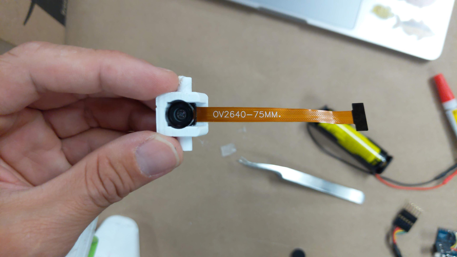
- OV2640 wide on a 75mm
- TinyML
- 18650 Li-ion Cell
- 1mm JST 2 pin connector
- XT30 connector pair
- 2x3 DuPont connector pair and pins
- Micro SD Card X2 (formatted in FAT32 or MS-DOS(FAT))
Tools
- Soldering Iron
- DuPont Crimping Tool
- 3D Printer
- Hot glue Gun
- Micro SD card Reader
- FTDI USB to Serial adaptor (for ESP32 programming)
Gather All the Parts.

Gather All The Parts.
3D Print the Housing (3 Pieces)

https://gallery.autodesk.com/projects/169803/camerawifiai-platform
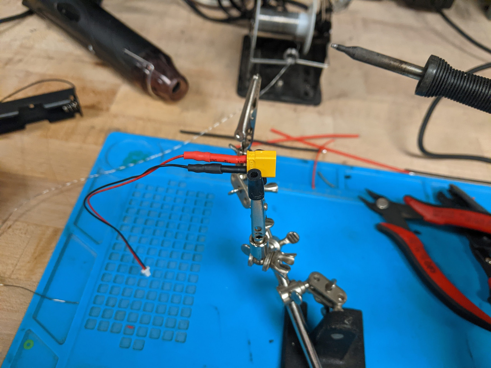
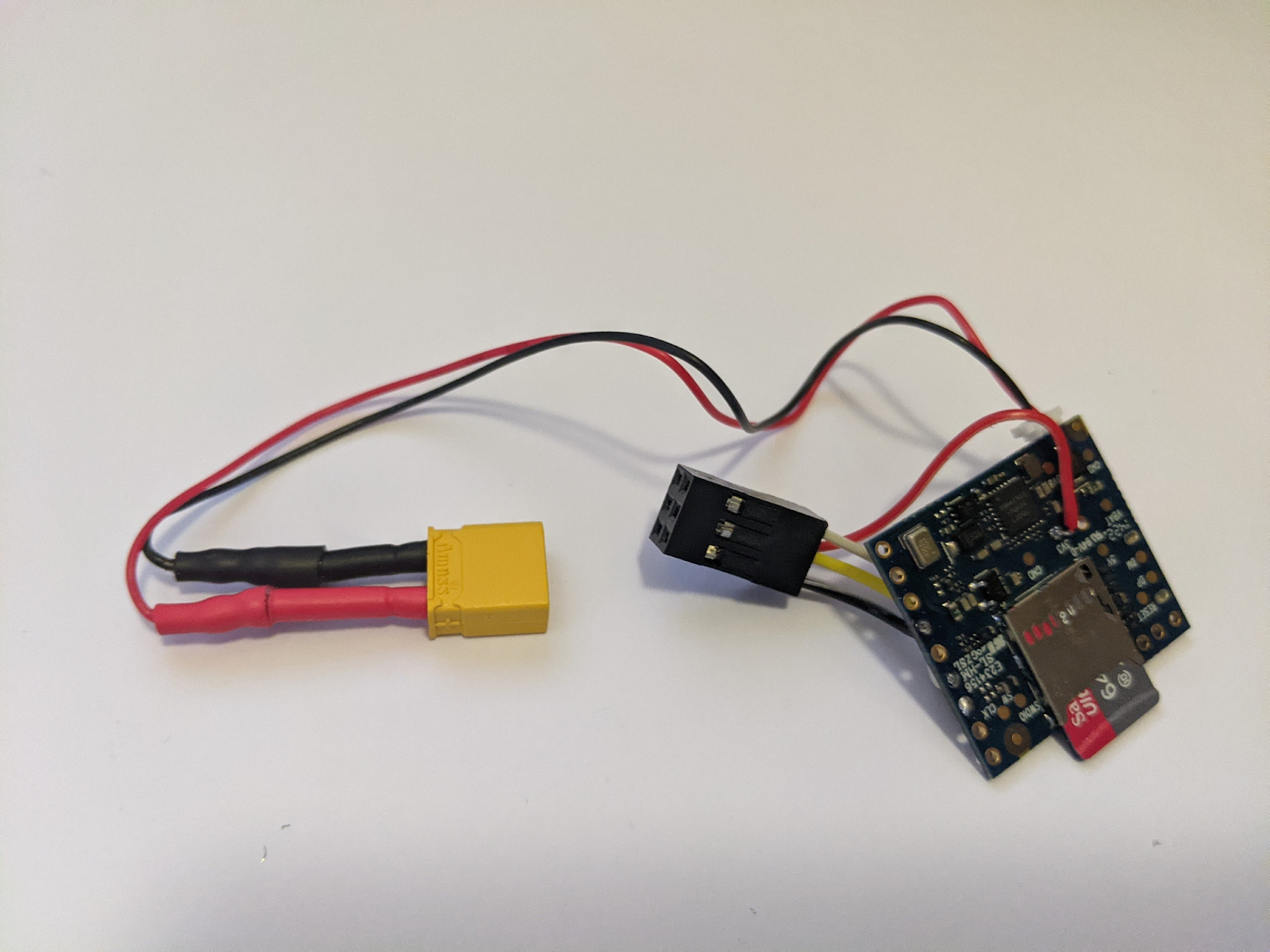
Prepare the Main Power Cables
- Solder the 1mm JST 2pin to the XT30 connectors.
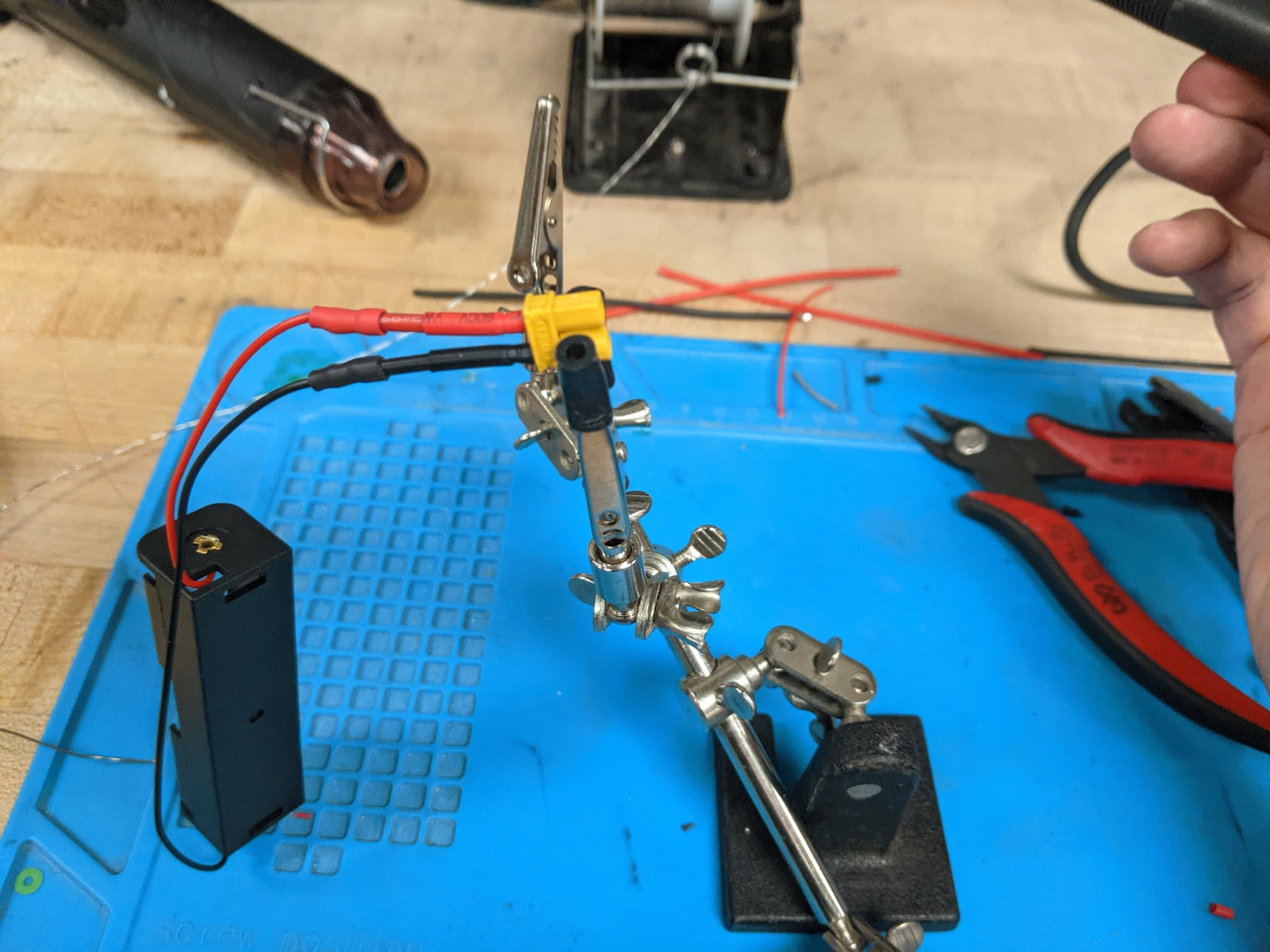
- Solder the Battery holder to the XT30 connectors.
Prepare the Data and Power Cable Between the ESP32 and the TinyML Board.
ESP32 Side
5V (Brown) Tx (White)
3V3 (Red) Rx (Yellow)
IO0 (Green) GND (Black)
TinyML Side
Tx (White)
3V3 (Red) Rx (Yellow)
GND (Black)
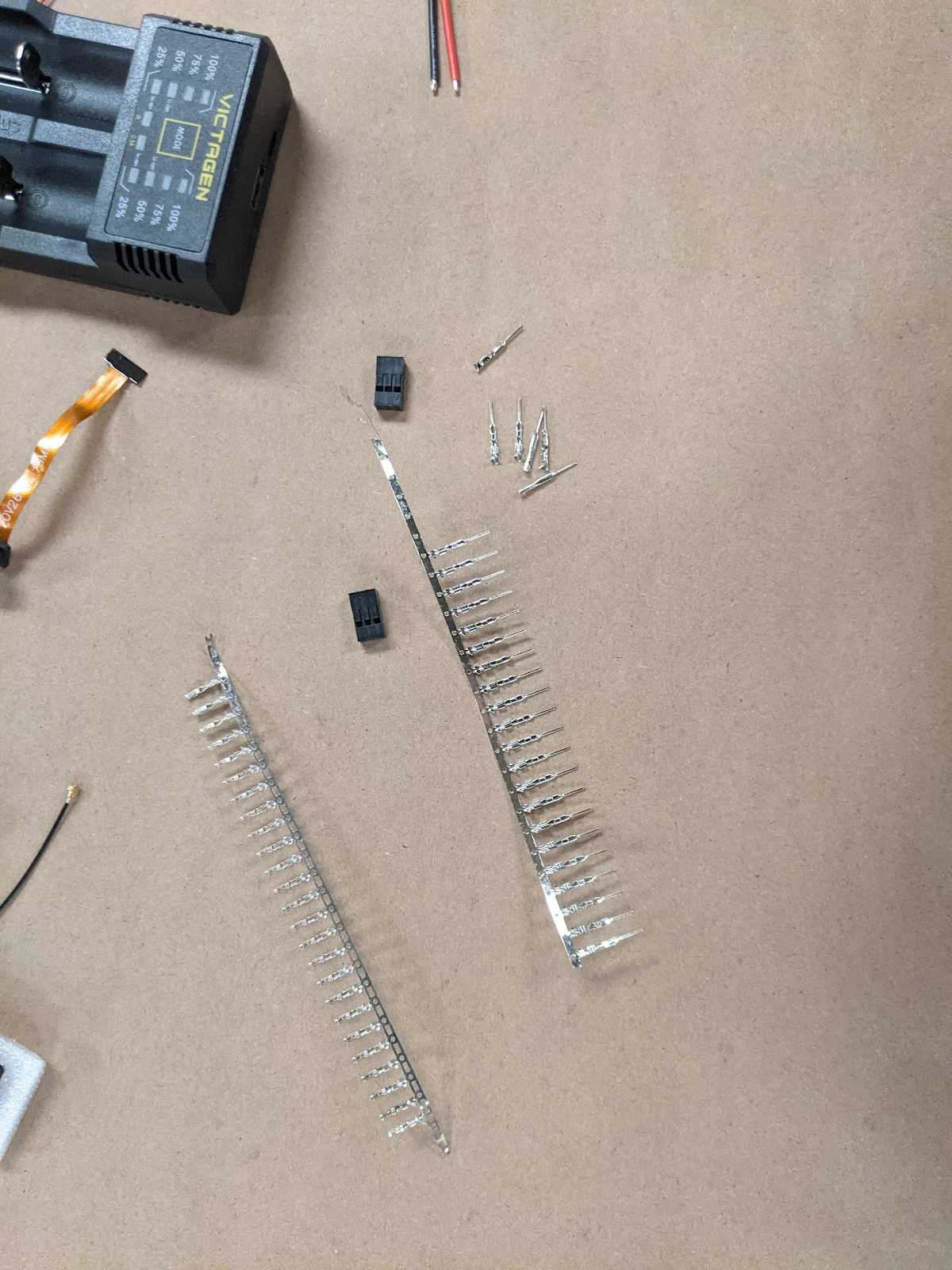
- Crimp the 2x3 DuPont connector pair and pins. (Video)
- Six pin connections betwixt ESP32 and the TinyML board. (Dupont 3x2 connector, pins on the ESP32 side).
- 5V and IO0 are used for programming (To FTDI Serial to USB cable). The 3V3 is used in the backpack and takes power from the 3V3 test pad on the TinyML.
- Solder the 6-pin cable to the ESP32.
- Solder the other connector to TinyML.
Connect the 3V3 power wire to the test pad on the TinyML.


Assemble the Lens
- Test the hinges of the camera holder. If it is too snug you may need to use the soldering gun to melt the holes a bit.
- Remove the cover of the camera lens and slide the camera into the holder.
- Gently feed the cable through the gap between the base and the holder while carefully pressing to fit the holder to the base. Make sure to not touch the lens of the camera.
- If the camera is too loose you may use some hot glue to hold it in place. Be careful not to damage the cable!


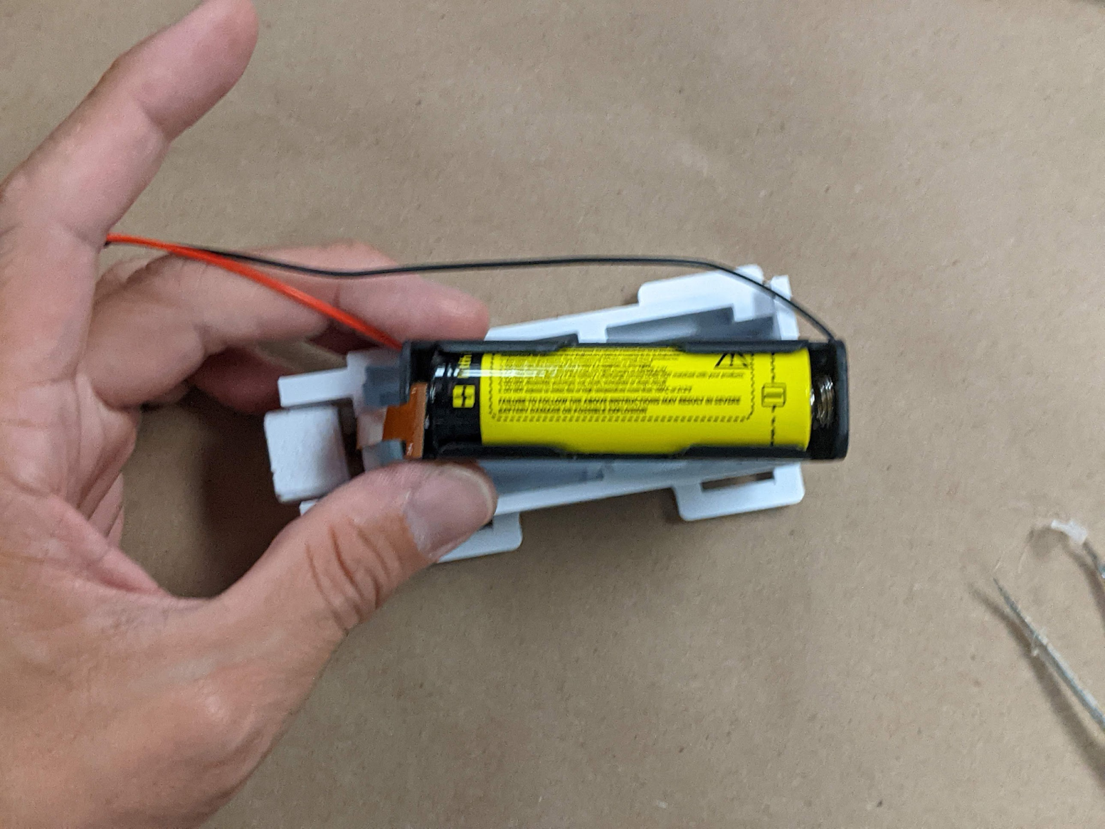
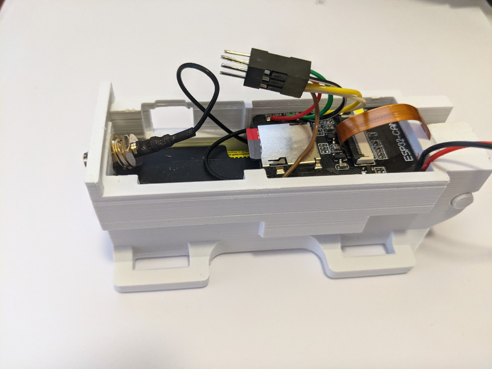
Install the Battery
- Insert the battery, and make sure the black and red cables on both sides align with the slot in the base so that they don’t get pinched.

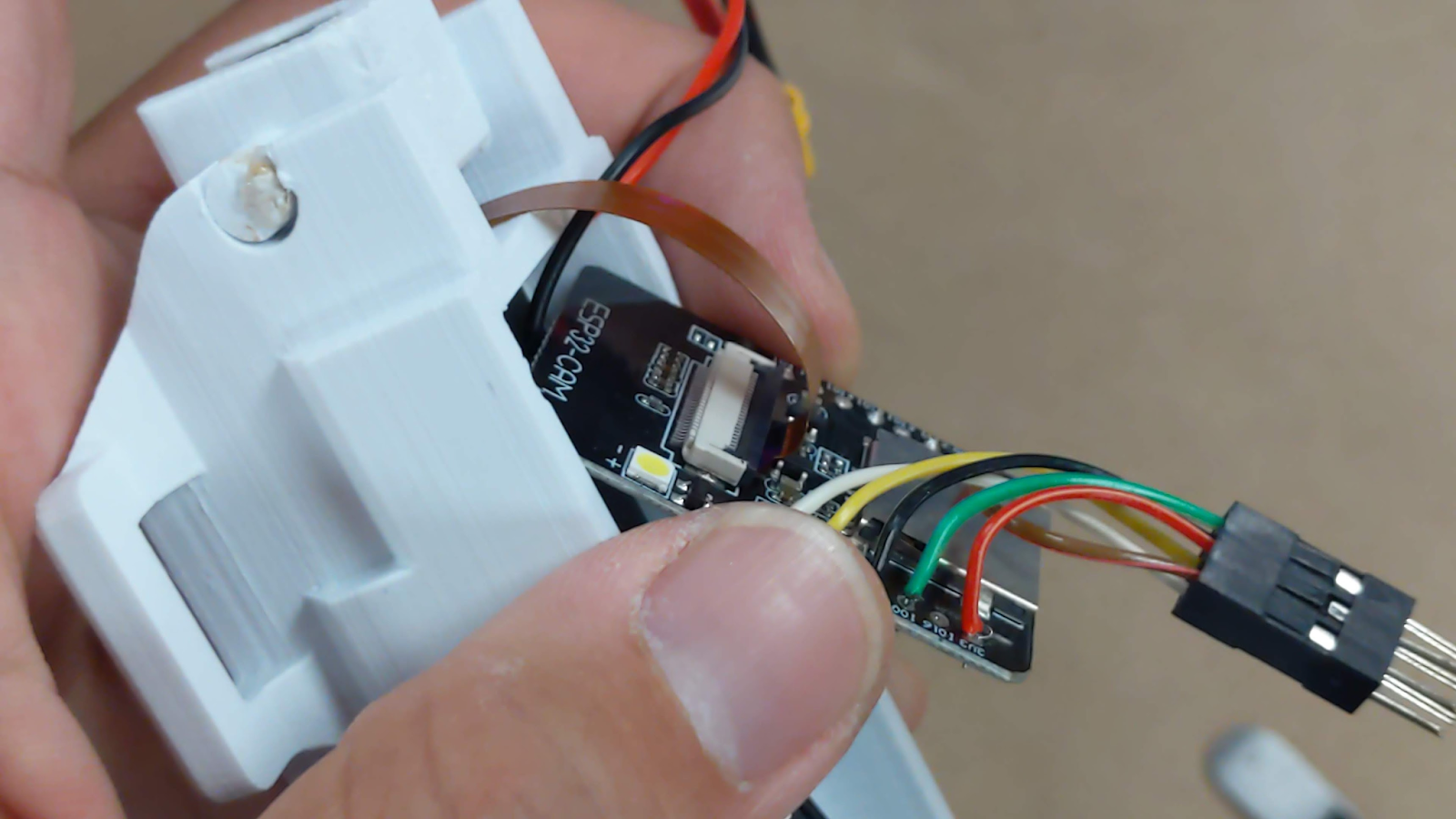
Install the ESP32 Board
- Carefully open the FPC Cable holder (fragile) on the ESP32.
- Insert the Camera FPC Cable in place and close the locking level.
- Flip the ESP32 board and attach the u.FL-to-SMA cable.
- Insert the MicroSD card (formatted as FAT32 or MS-DOS FAT). Put the ESP32 board into place.

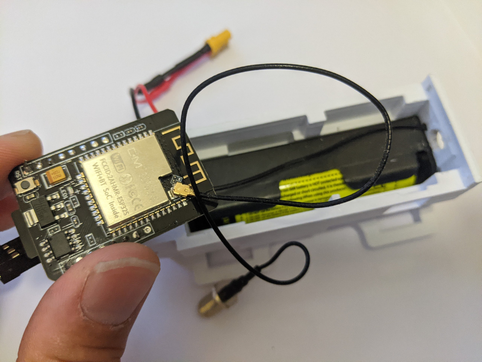

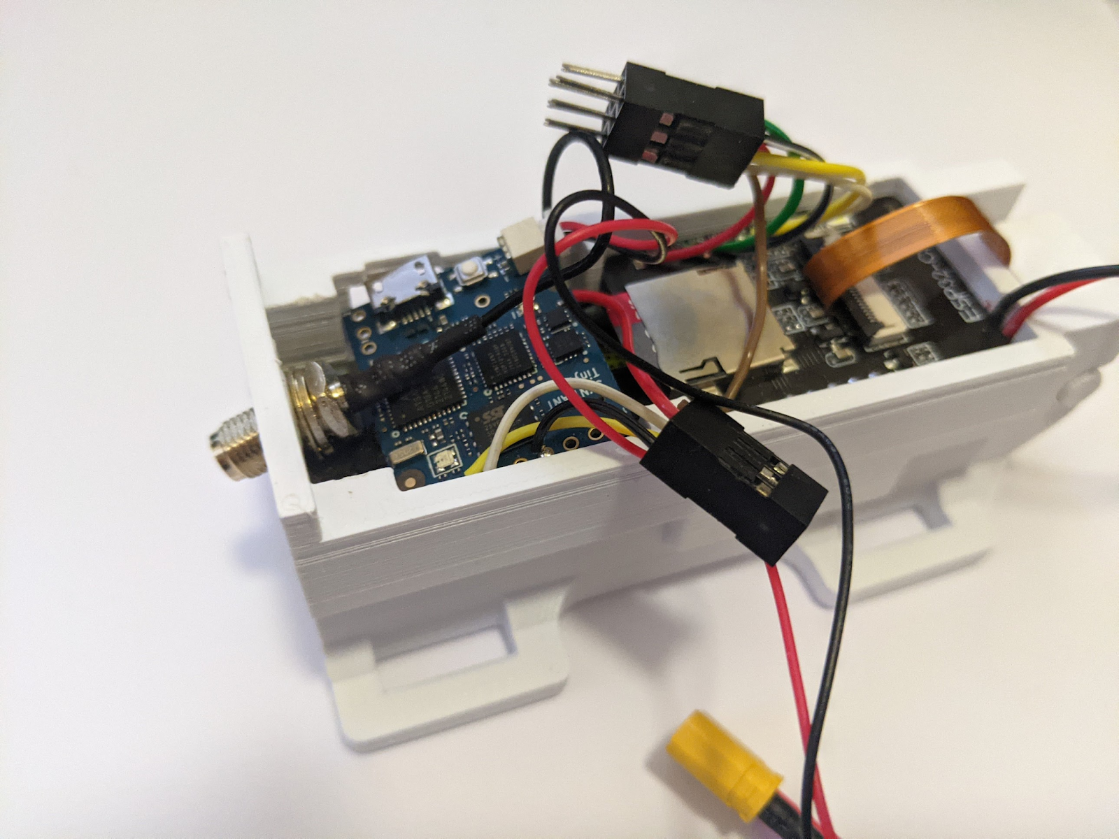
Install the Tiny ML Board.
- Insert the Micro SD card and the XT30 to JST cable into the TinyML board.
- Tug the extra slack of the u.FL-to-SMA cable underneath the ESP32 board and push the SMA connector through the mounting hole.
- Slide the TinyML board in between the battery and the SMA cable.
- Attach the antenna.
- Do not connect the XT30 power cable or 2x3 Dupont cable yet.


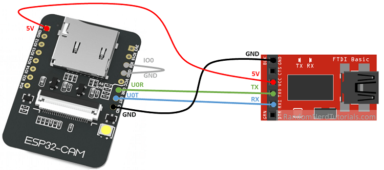
Prepare ESP32 CAM for Firmware Uploading
- Connect jumper wires from the 2x3 dupont pins on the ESP32-CAM to the FTDI Serial to USB cable (You may follow the Random Nerd Tutorial to see the actual wiring as in the diagram below. Note that the color of the wires does not correspond to ours).
- Additionally, since we didn’t solder the second GND wire (the gray wire above), we can use a breadboard to connect the GNDs on both ESP32-CAM and FTDI board together with the IO0 cable to share the same ground.

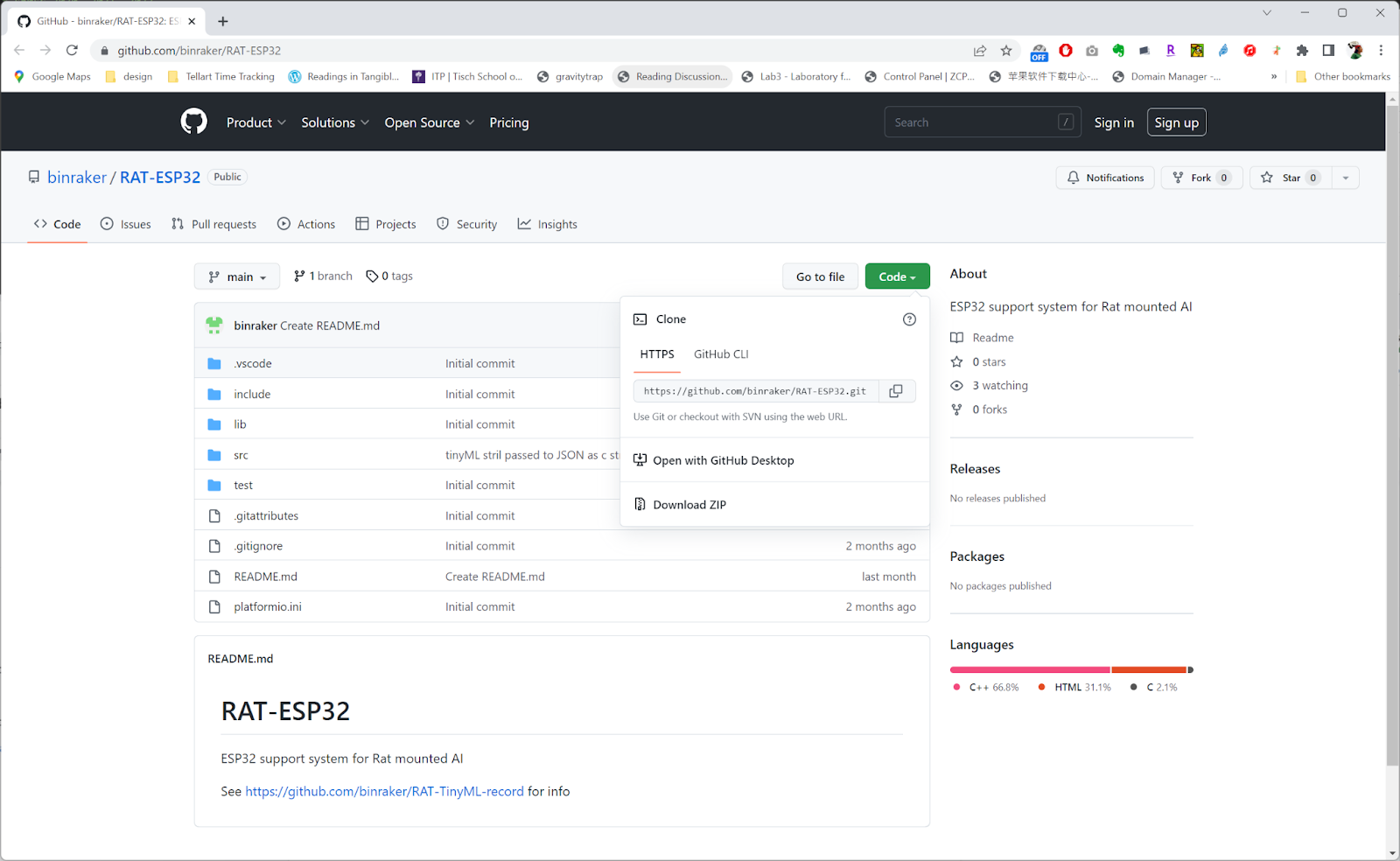
Install the Firmware Onto the ESP32-CAM
Video steps to follow.
- Once the wires are connected, we can go ahead and download from our GitHub repository https://github.com/binraker/RAT-ESP32 and upload it to the ESP32 CAM board. To do this we recommend using the Microsoft VS Code plug-in Platform IO because it makes installing the libraries easier. Alternatively, you might use the Arduino IDE. If that’s the case, please make sure that the ESP32 board library is at least 2.0.4
- Download the ESP32 code.
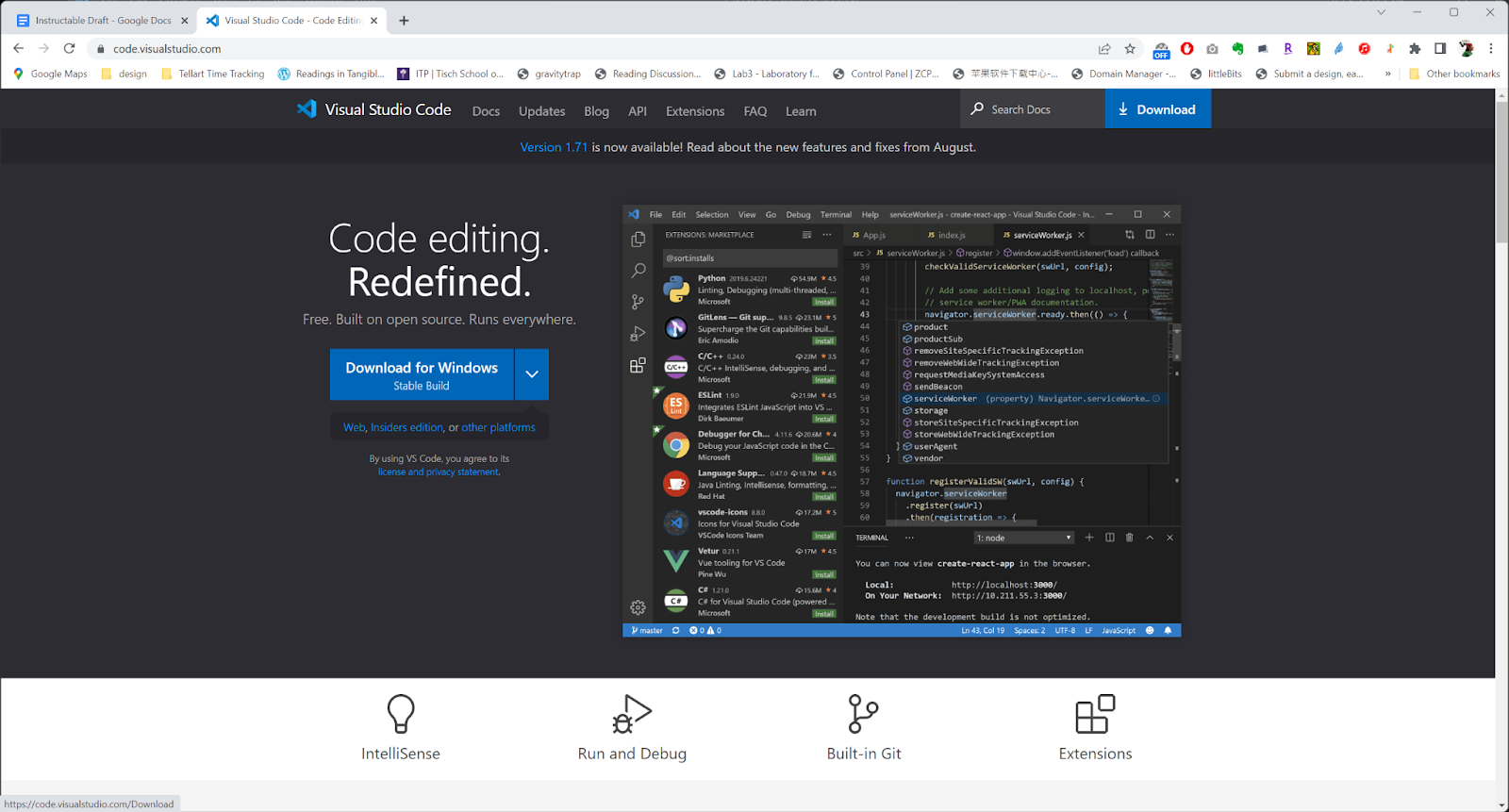
- Install VS Code.
- Install Platform IO.
- Open Platform IO and load the project.
- Build the project and upload it to the board (It might take a while for the first time cause Platform IO needs to grab the necessary libraries).
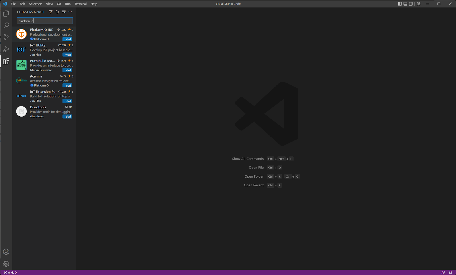


(seeing this notification means that Platform is still pulling the libraries)
Verify the ESP32 CAM Code
- After a successful upload, we can now unplug the wires from the FTDI Serial-to-USB cable and connect the 2X3 DuPont connectors between the ESP32 CAM board and the TinyML board. We can also connect the XT30 power connectors at this time.
- If we check the wifi on our computer now, we should see an SSID called RAT_XXXXXXXX available. Connect to that wifi with pw:123456789 (this will make you lose the internet temporarily).
- Go to a browser and input 192.168.4.1 as the URL. It should prompt you to input your actual wifi network setting. You can choose to input it or hit cancel.
- If you chose to use your own wifi to let the ESP32 connect to the internet, you might need to go into your router to check the IP address assigned to the ESP32.
- Type in the IP address of the ESP32 on your browser, if we see the below interface then HOORAY! We have successfully uploaded and configured the ESP32 part.
You can click the start stream or get a still photo to test the camera on ESP32.


Install the Firmware Onto the TinyML Board.
video steps to follow
- Download the code.
- Connect the TinyML board to the computer through a micro USB cable (make sure your cable allows data transmission and not just power like many micro USB cables do).
- Go back to VS Code Platform IO and open the downloaded project (https://github.com/binraker/RAT-TinyML-record). Build it and upload it.


Done!
At this point, we have finished all the necessary steps. In the near term, we will publish more tutorials on how to use the recorded data and images to train a machine learning model and analyze the movement of the rat.