RaspberryPI Photo Camera - MagicBox
by feiticeir0 in Circuits > Raspberry Pi
2374 Views, 7 Favorites, 0 Comments
RaspberryPI Photo Camera - MagicBox
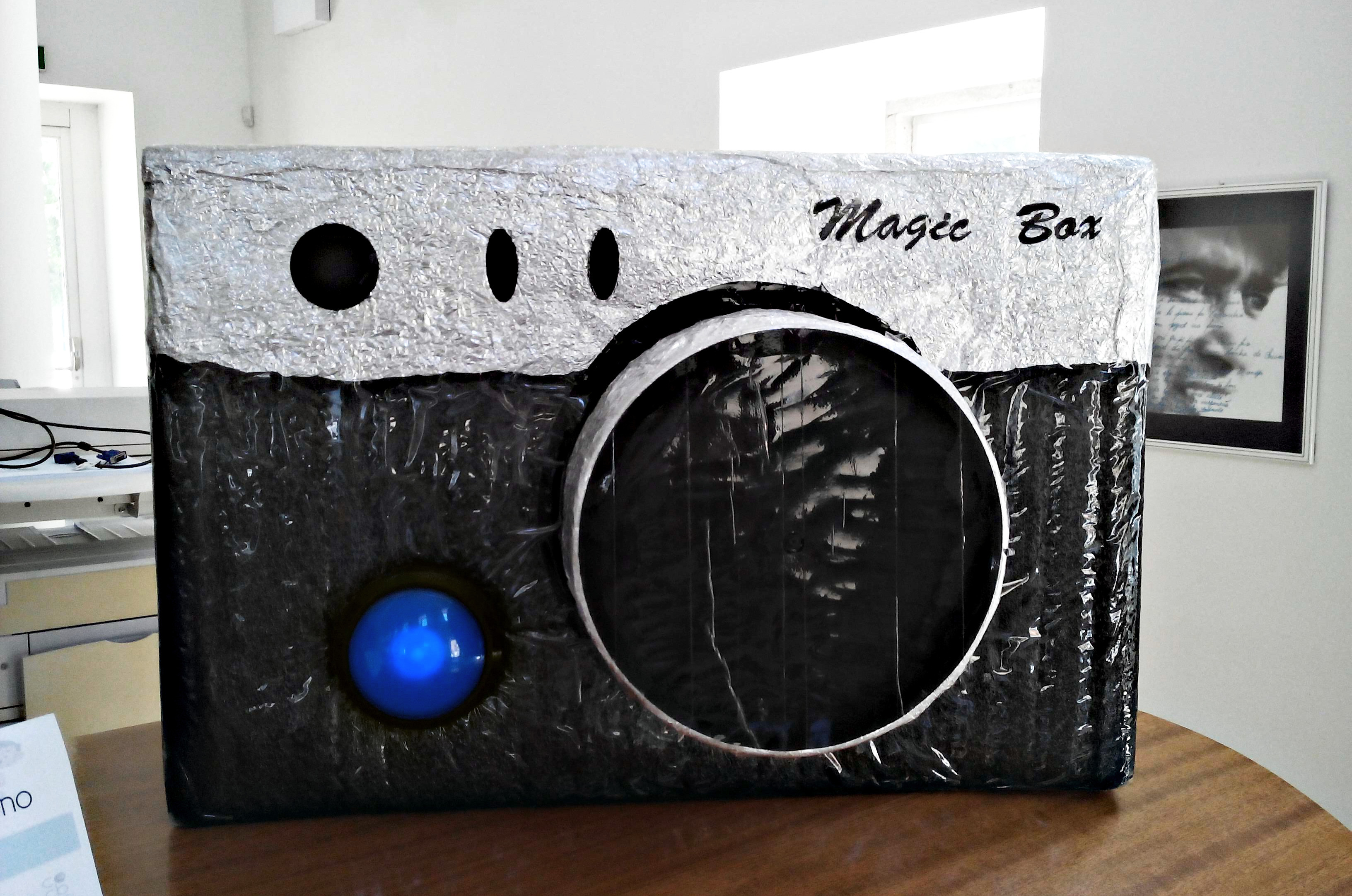

A while ago, I had this crazy idea to create a photographic machine out of a Raspberry PI. In my city, there was a small show where people would go and show what they were making or had make using electronics, computers, etc... I was like a poor man's Maker Faire, but at a local scope .
One was coming up, and, together with my wife, we build this thing.
How does it work ?
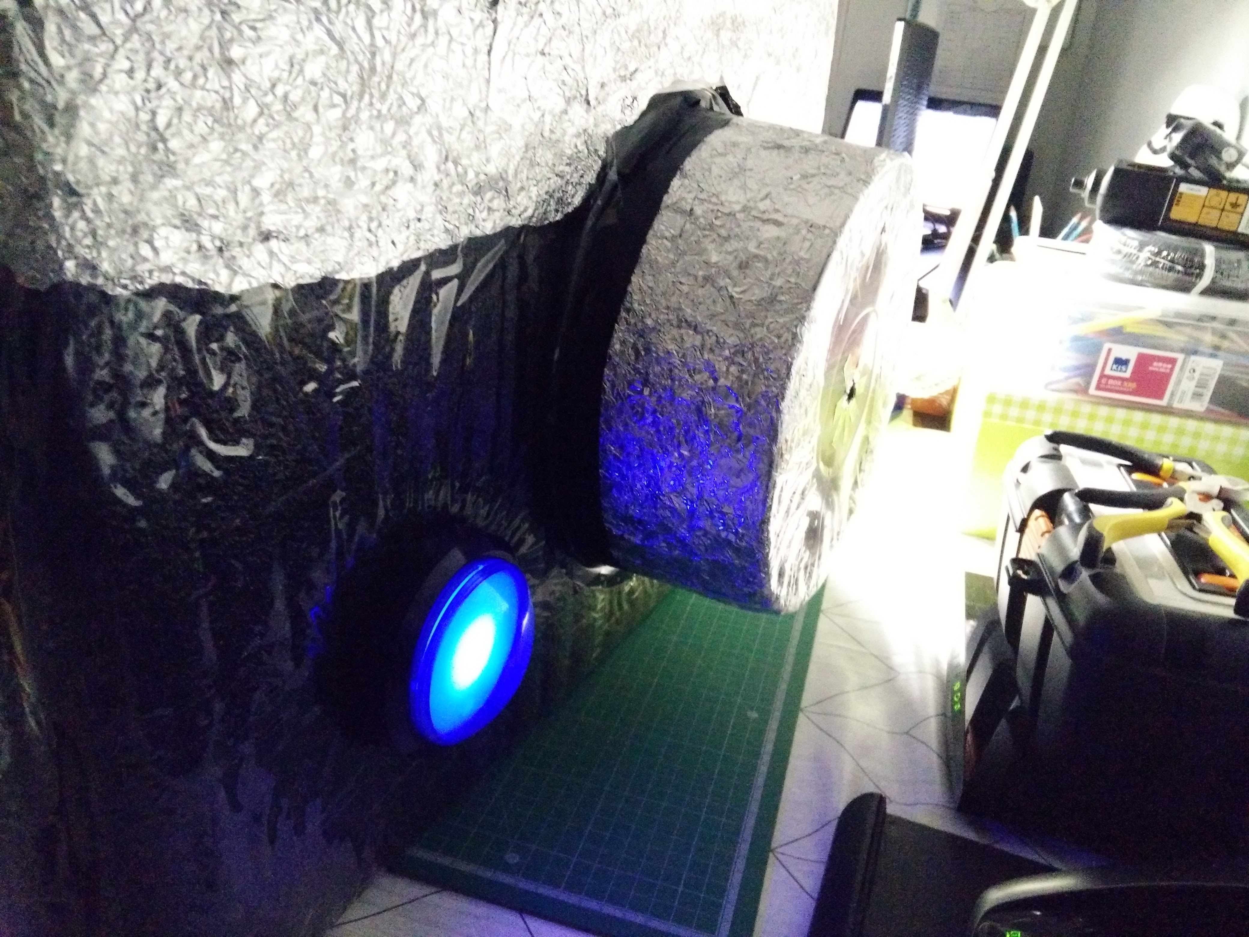
You press the blue button - it starts to blink - and after 3 seconds a picture is taken. On the other side of the camera there's a monitor that is showing a countdown and after the picture is taken, the preview of the photo.
You can now choose to send it to Twitter and Facebook or cancel and try again. It's that simple.
Everything is programmed in Python, making use of the PI framebuffer - No Xorg, no GUI are used.
Here's a video of the project working
Supplies
- Raspberry PI (I'm using version 2)
- Raspberry PI Camera (Using version 1)
- 3x Big Dome push Buttons
- TFT/LCD Monitor with VGA/HDMI
- MDF
- Metal hinges, screws, etc..
- Power Tools
- Spare time and lots of fun
Build
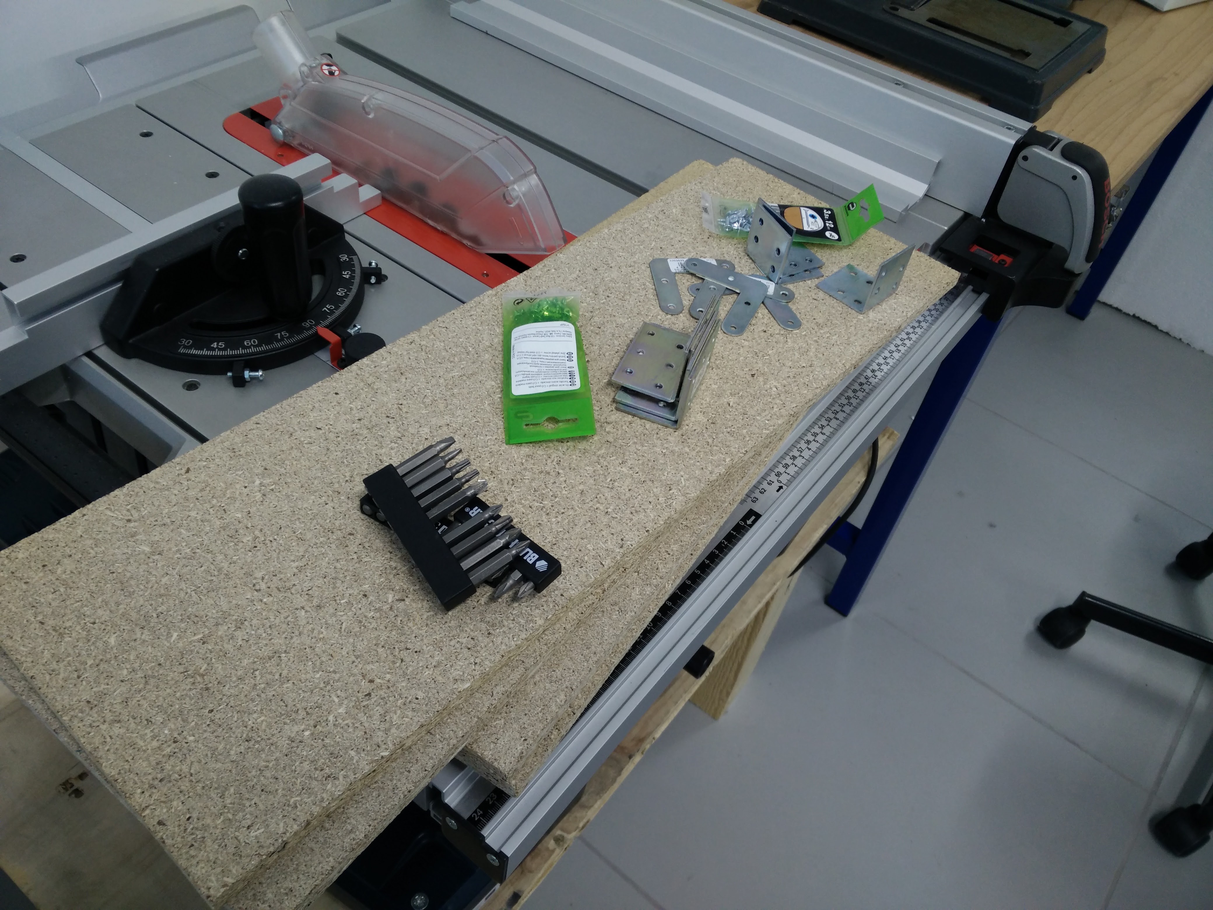
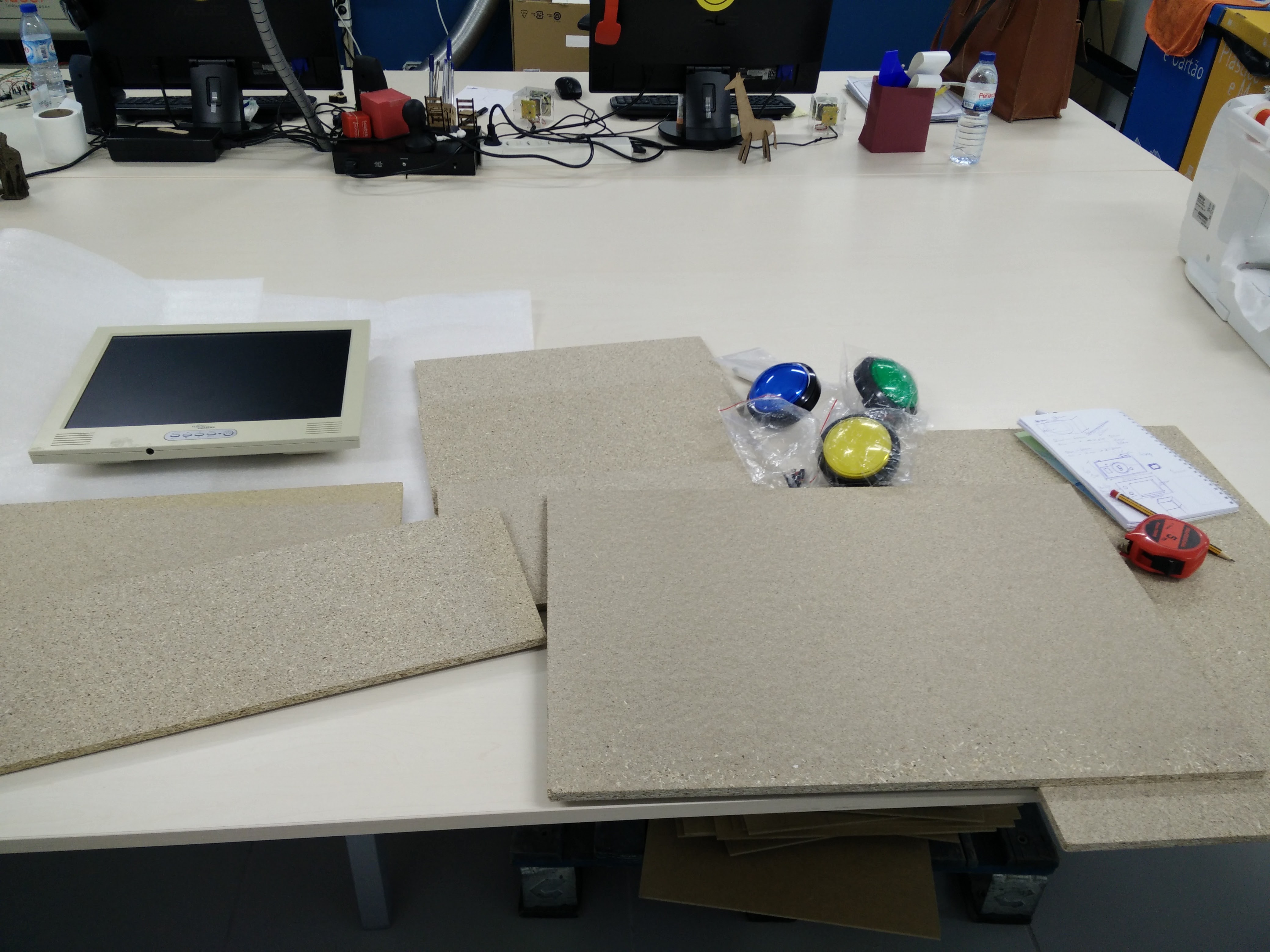
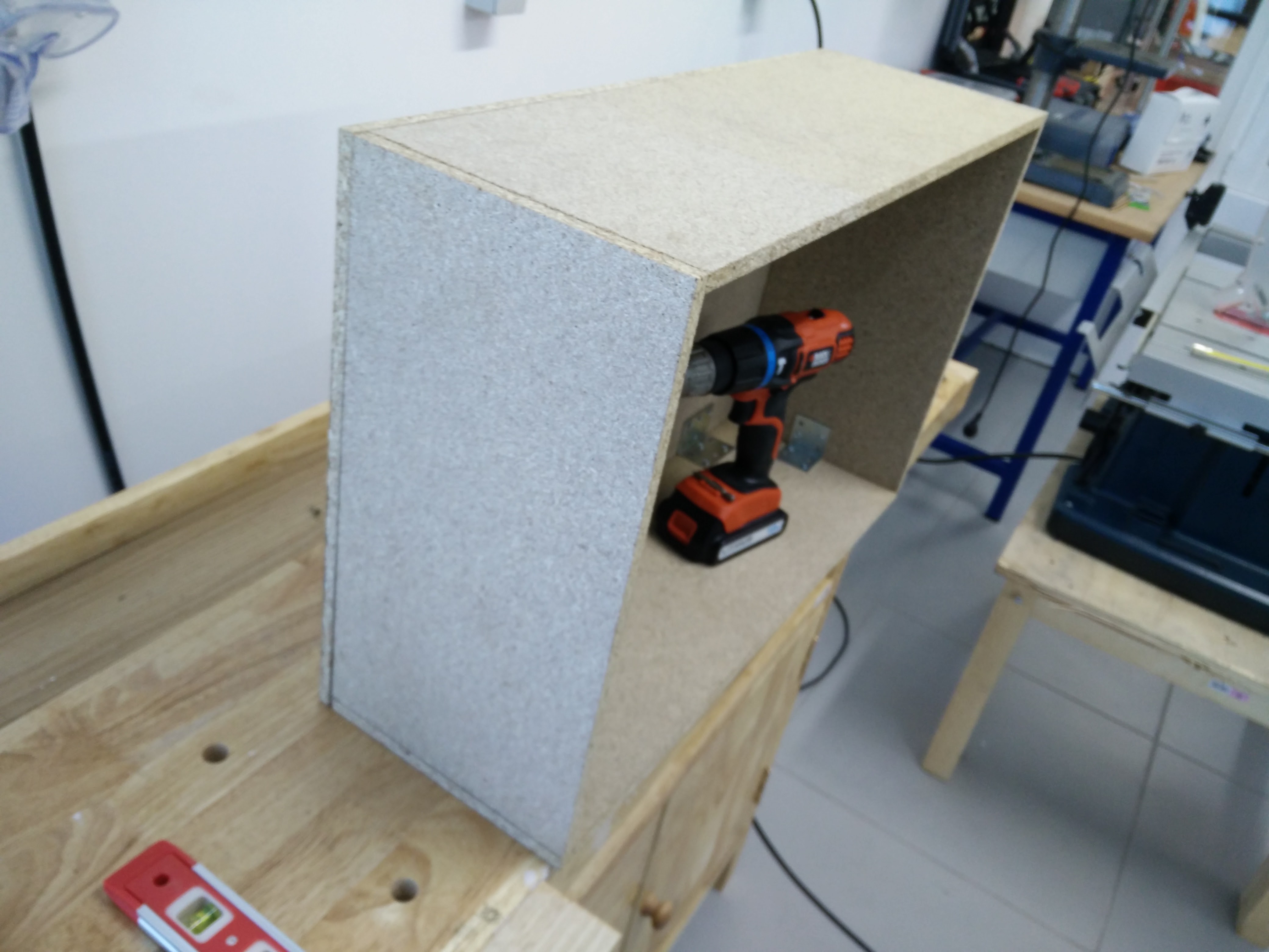
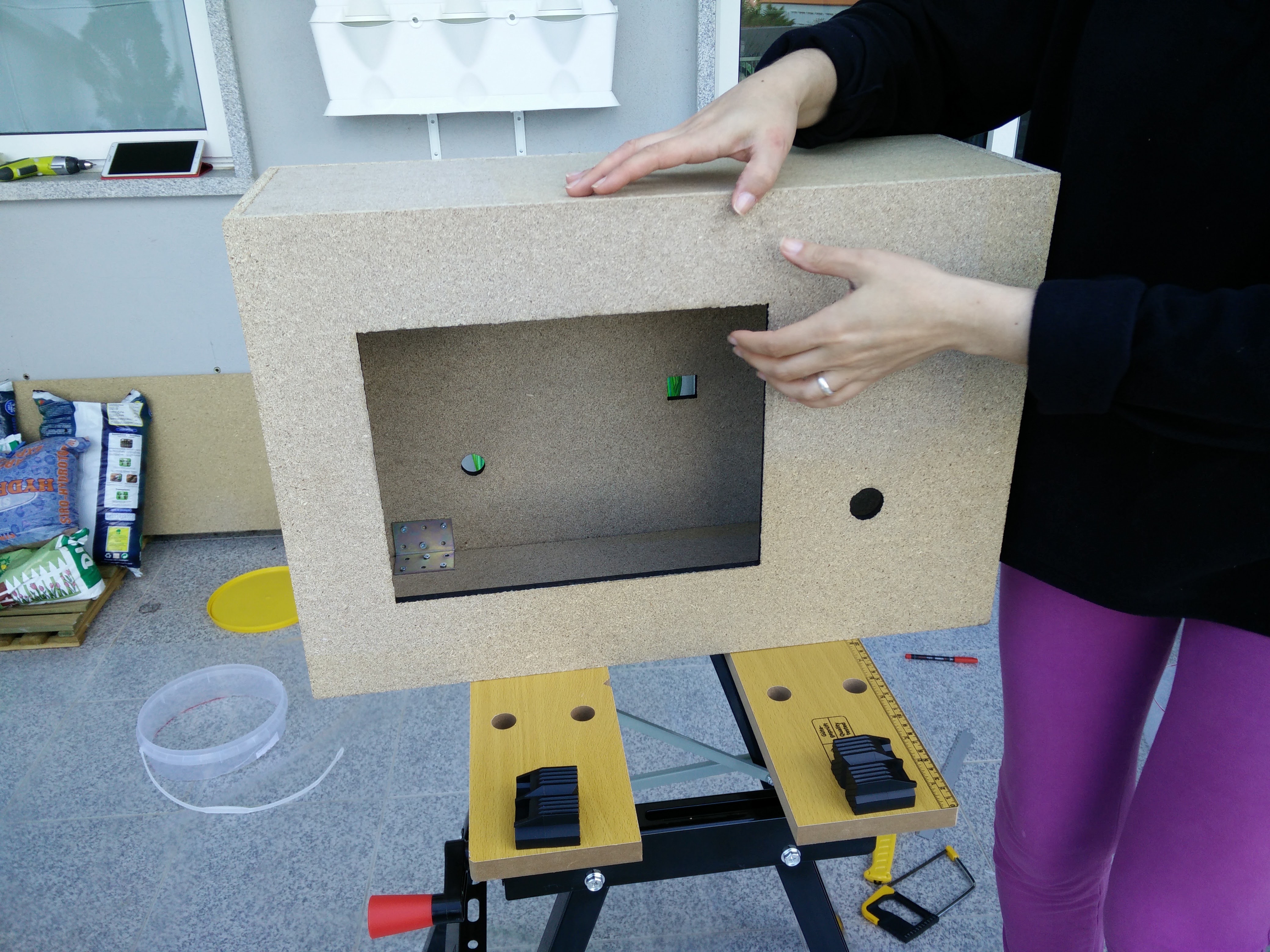
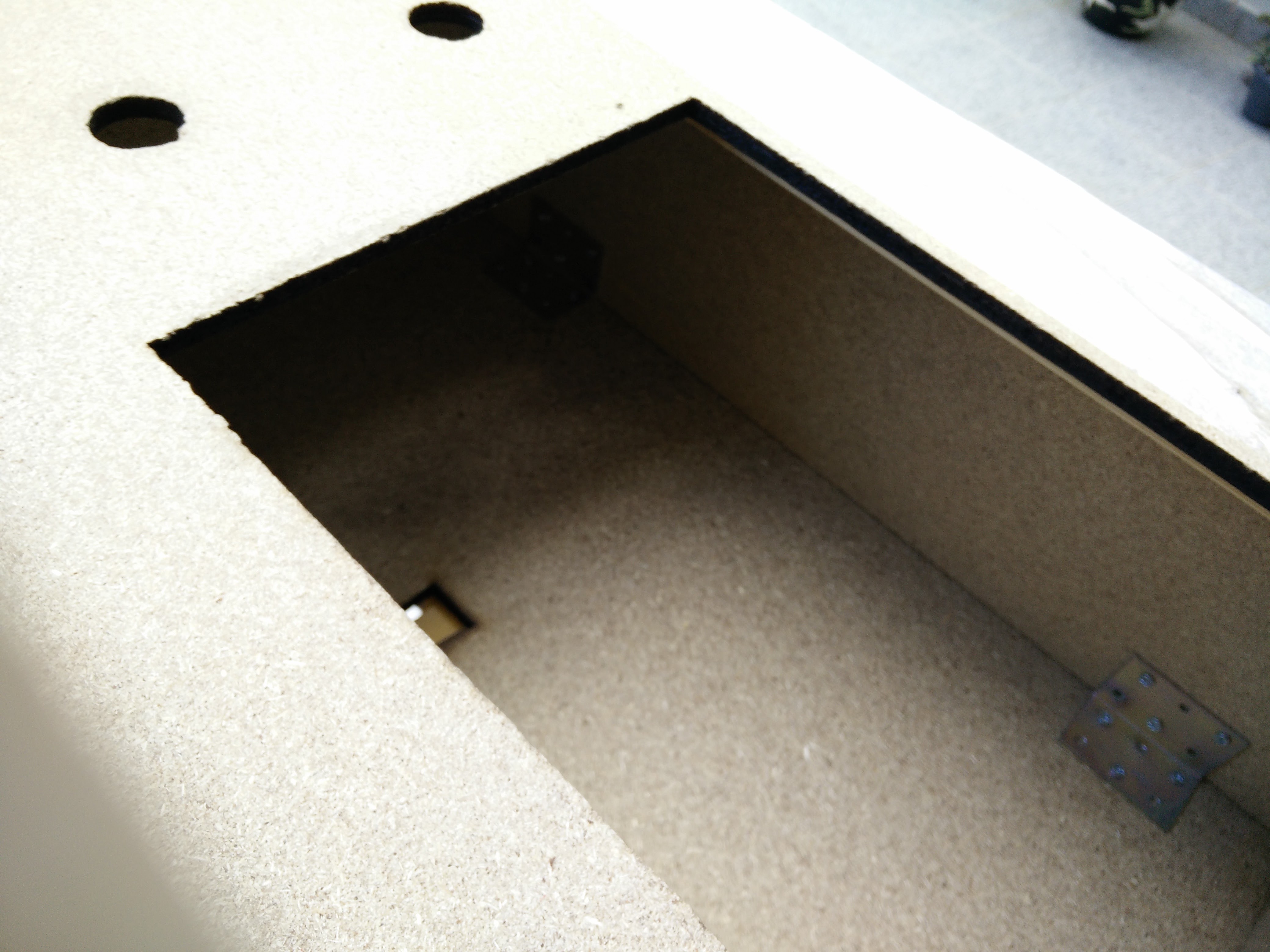
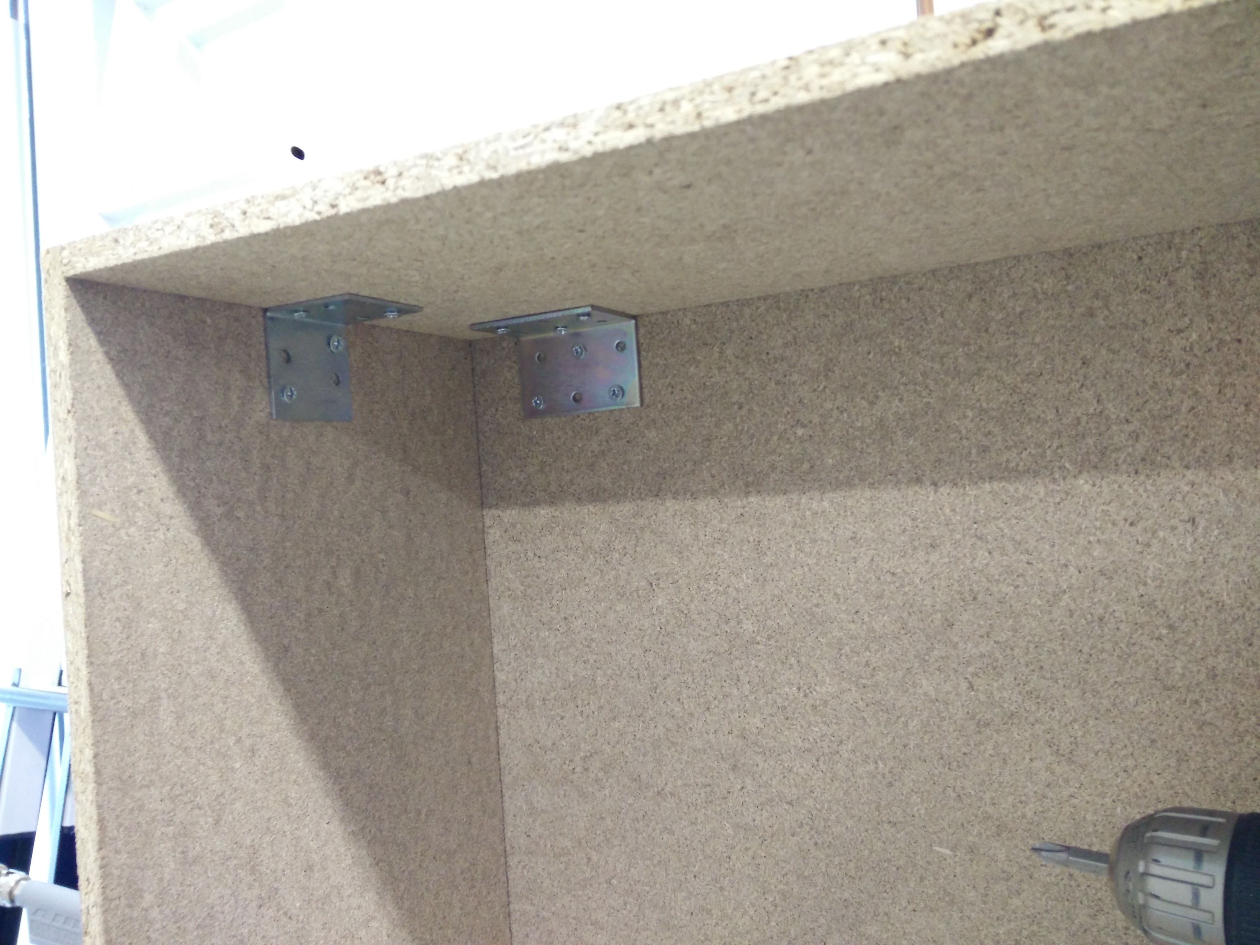
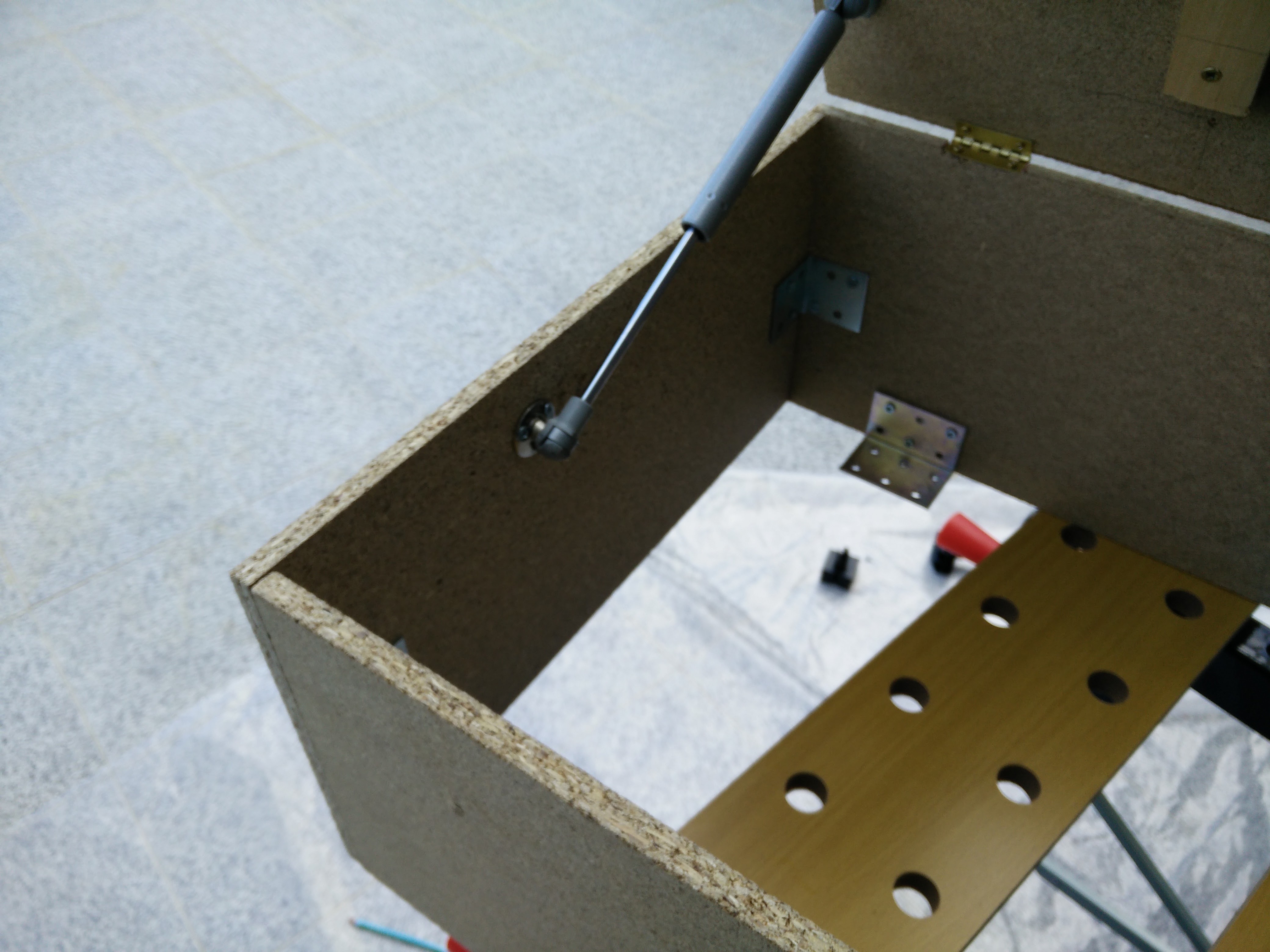
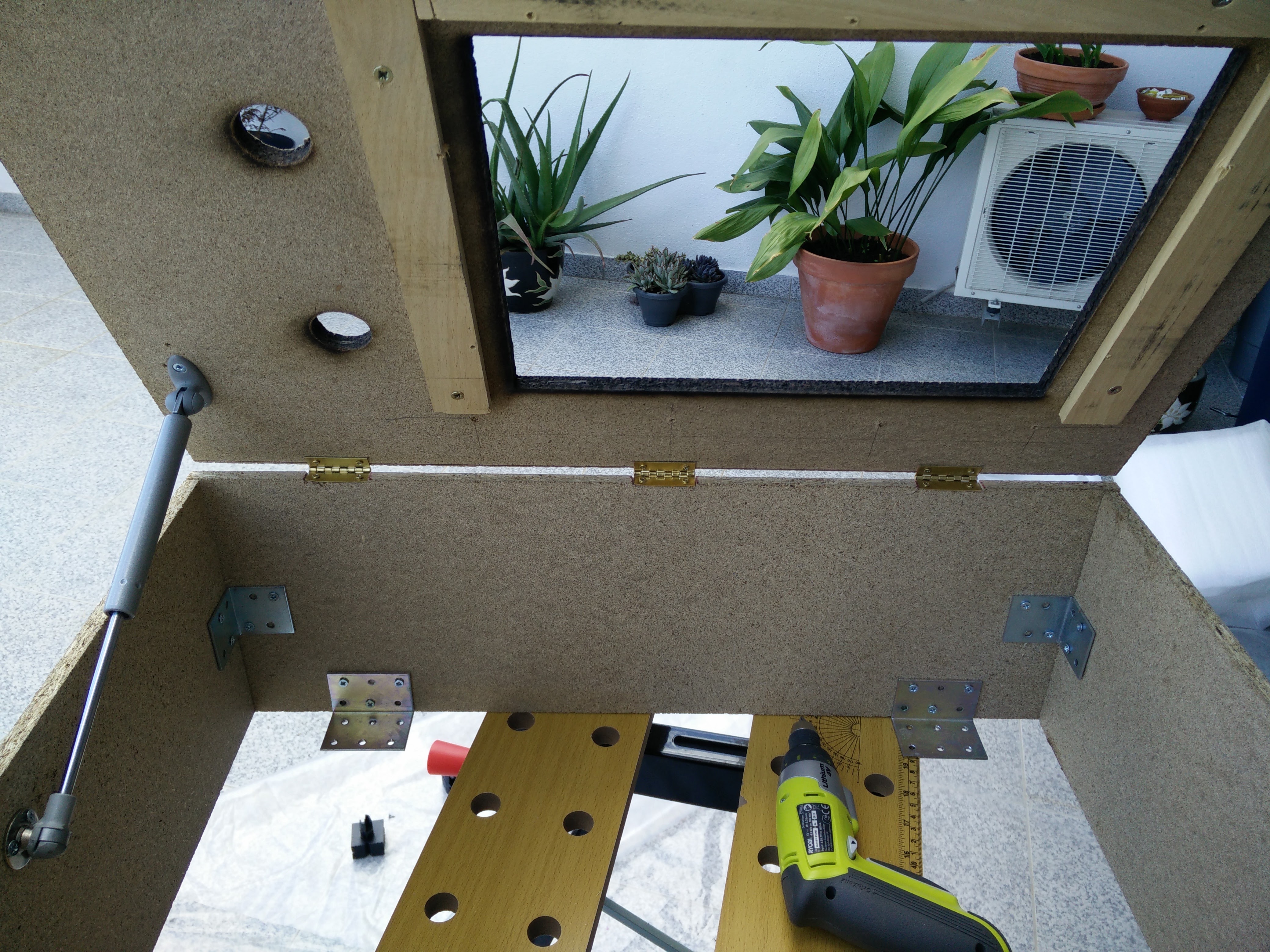
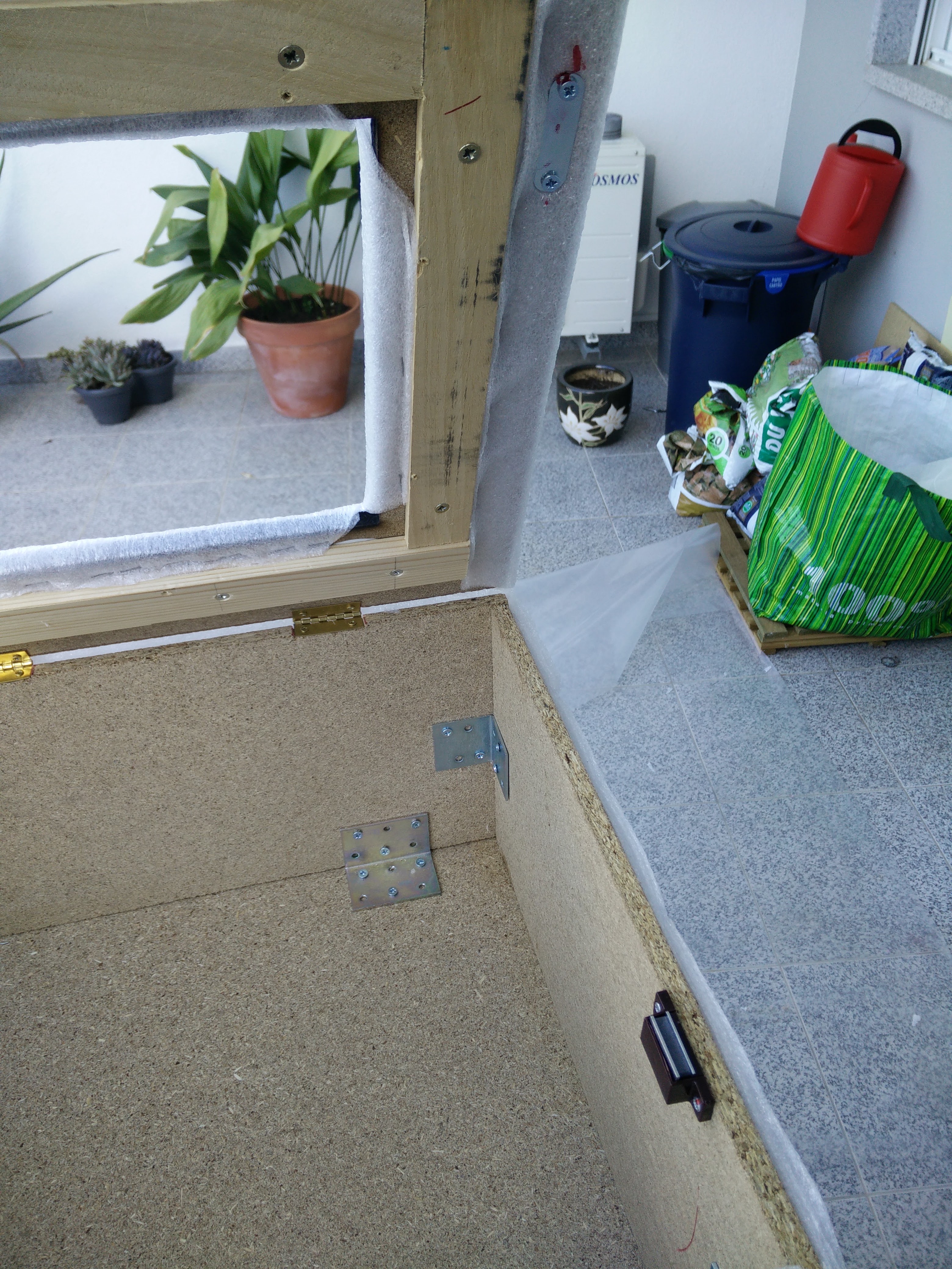
Building it was fun. A lot of cutting, painting and drilling.
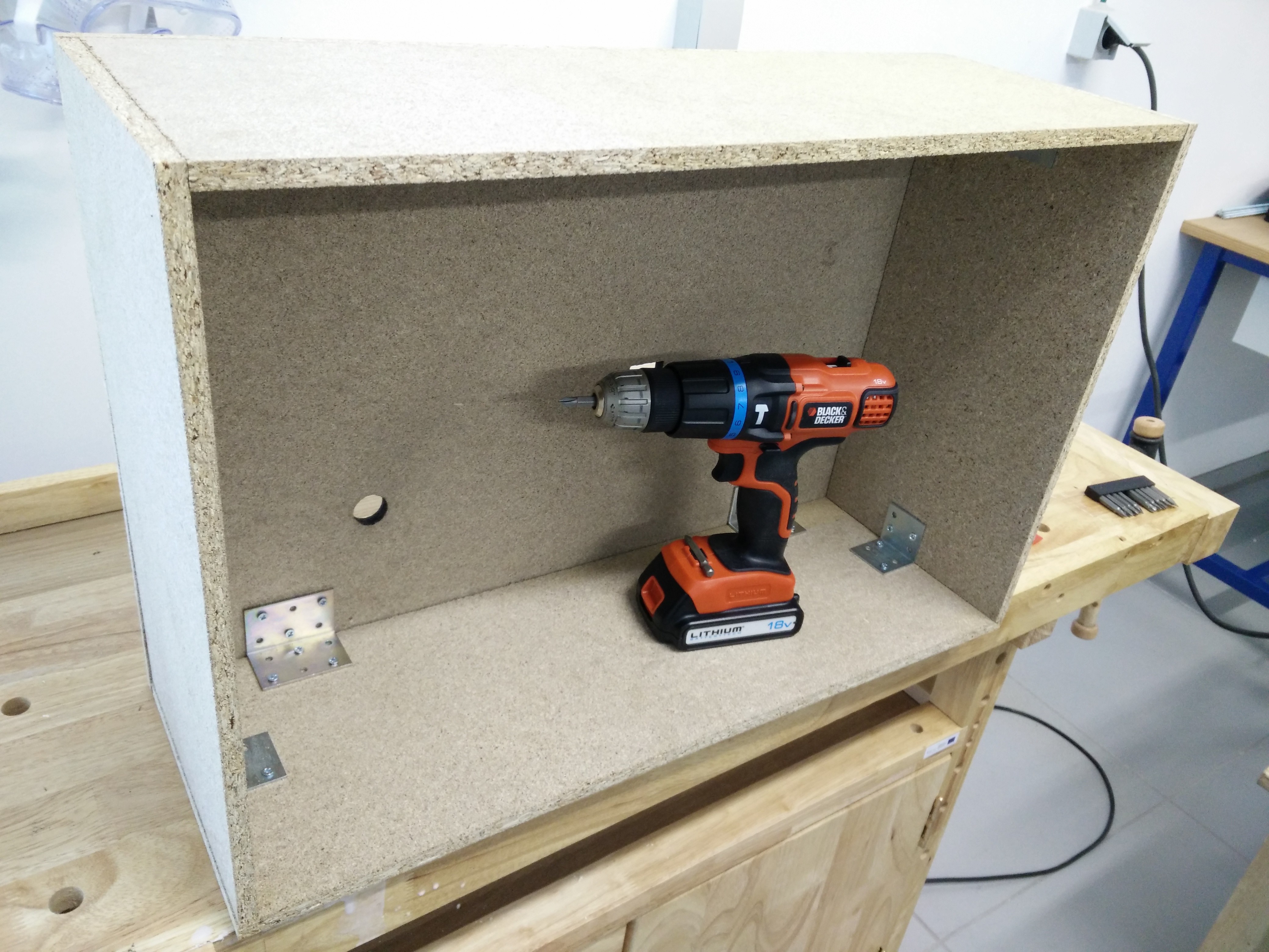
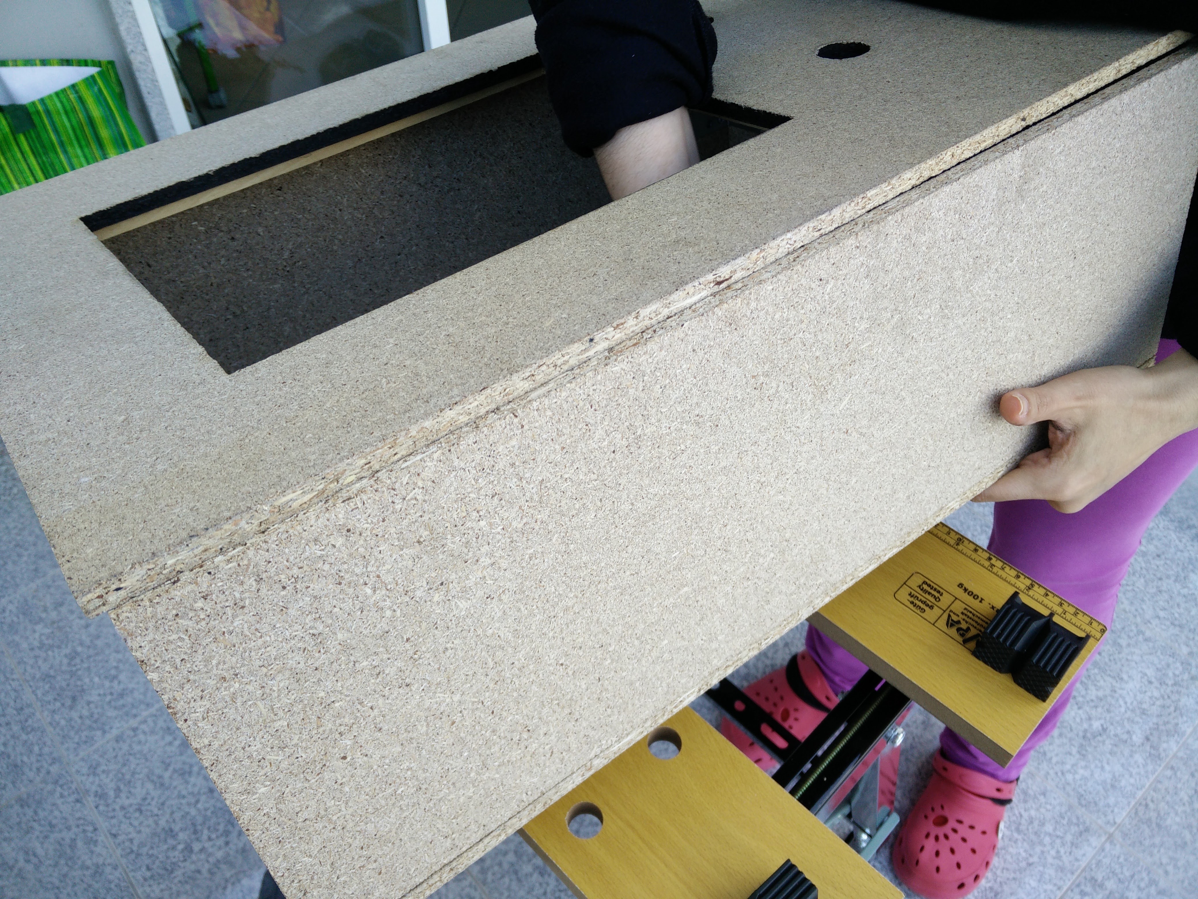
I used MDF panels for building the basic structure of the camera. They are light and easy to work with. Also, it was one type of wood the Laser machine at the local Fablab was able to cut.
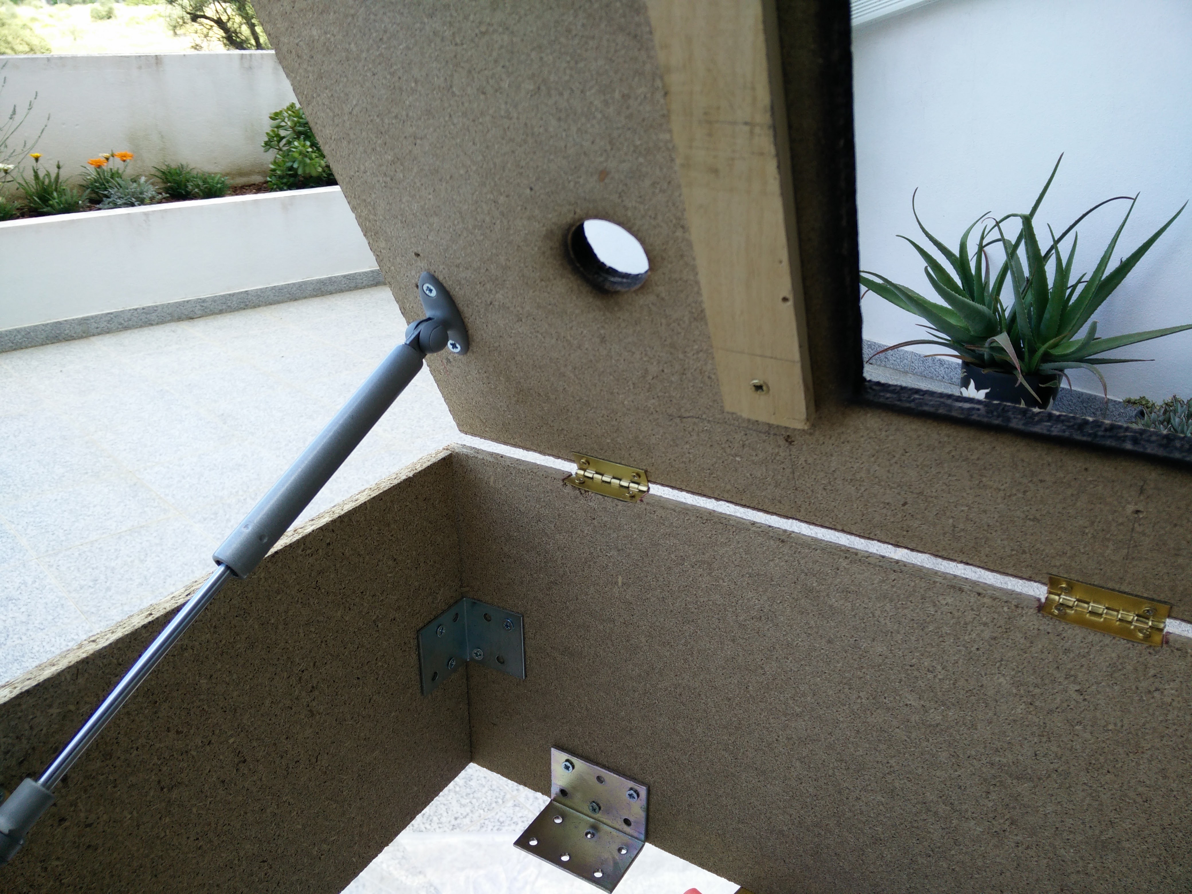
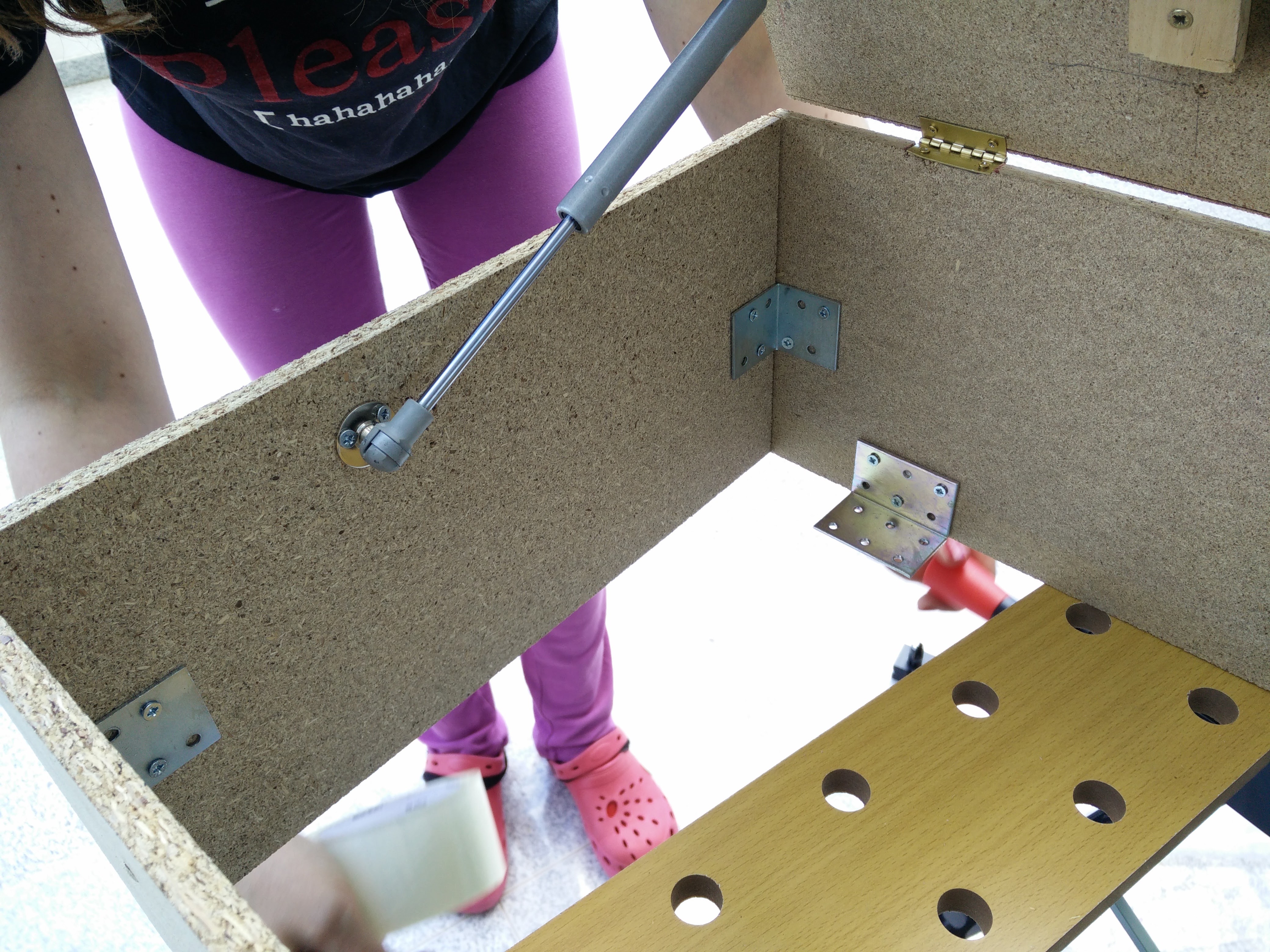
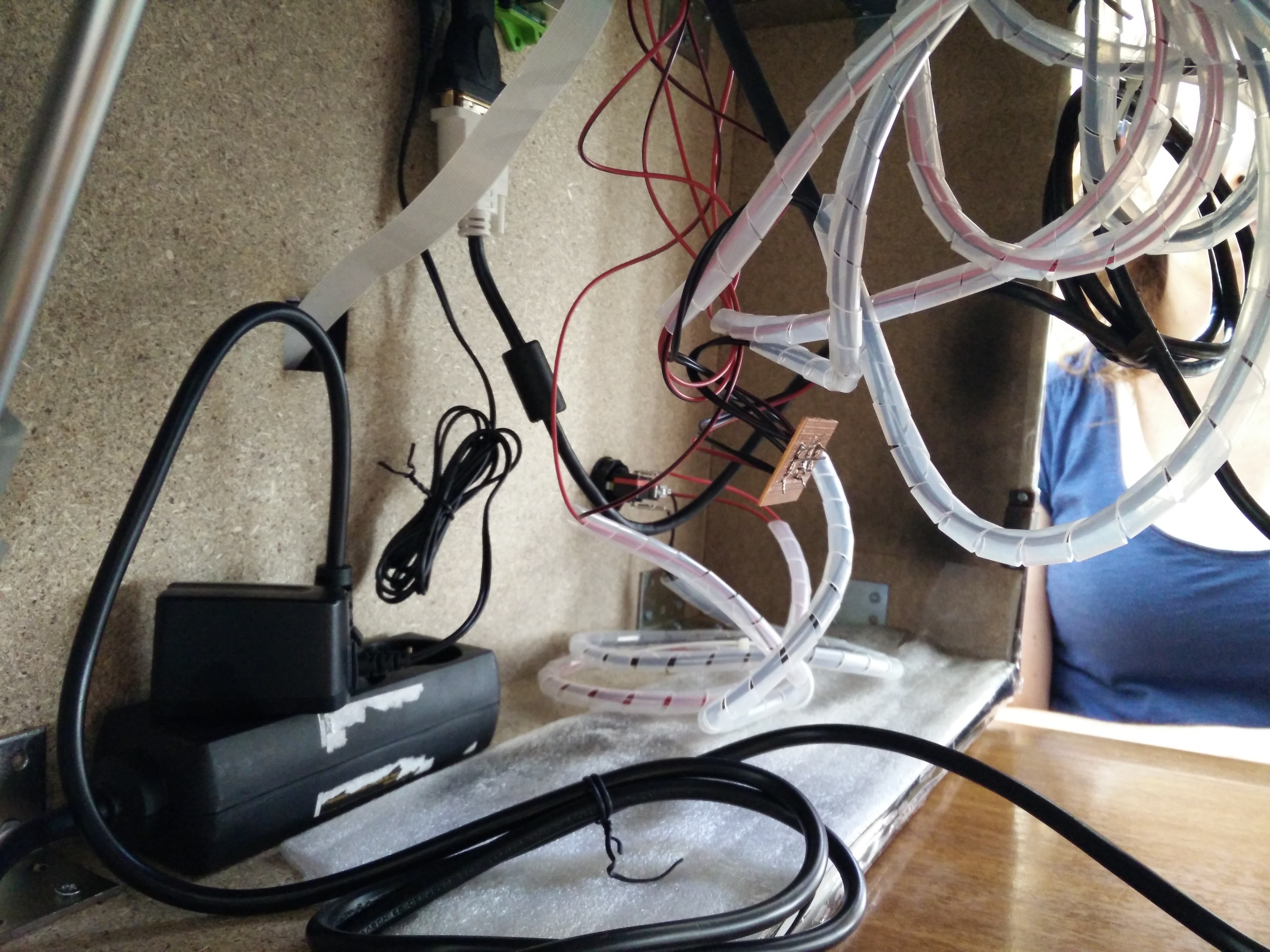
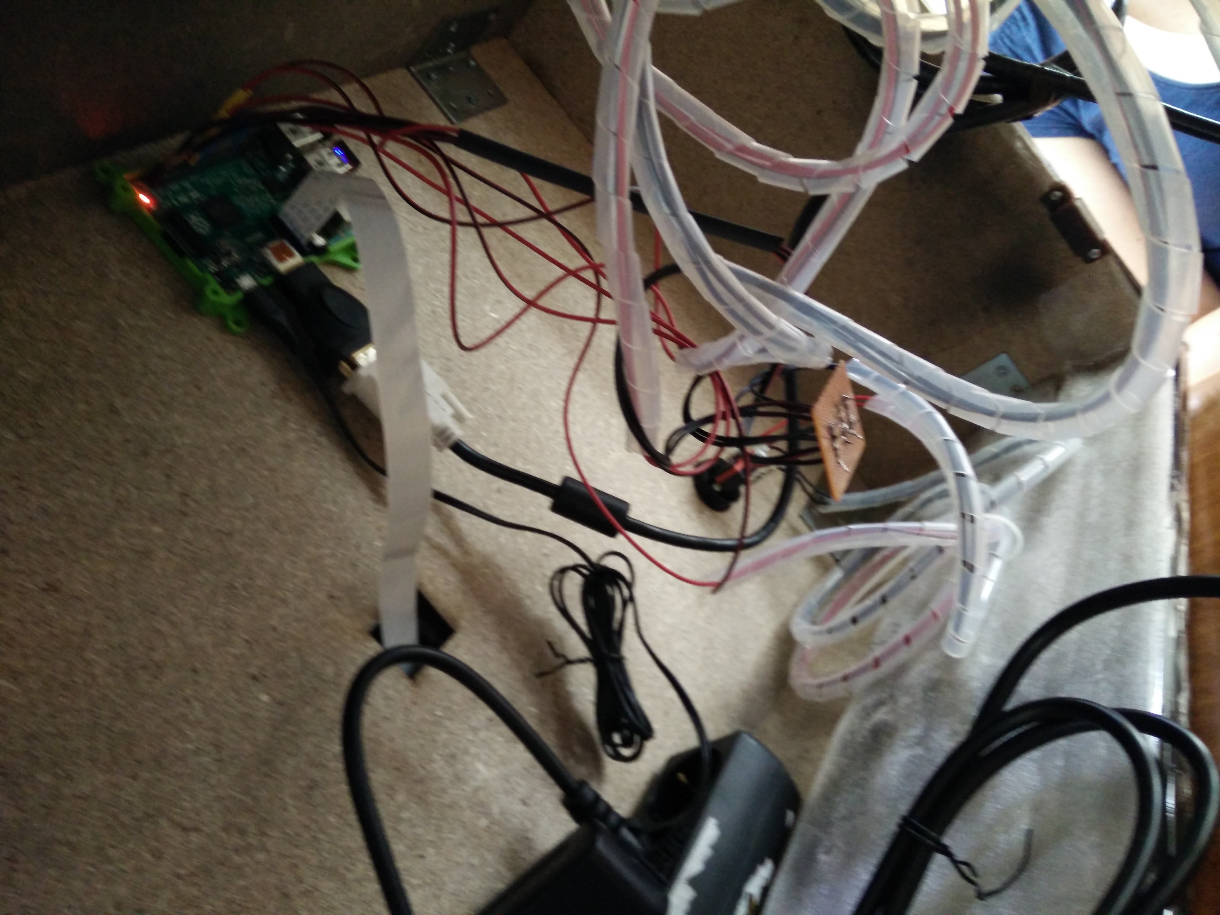
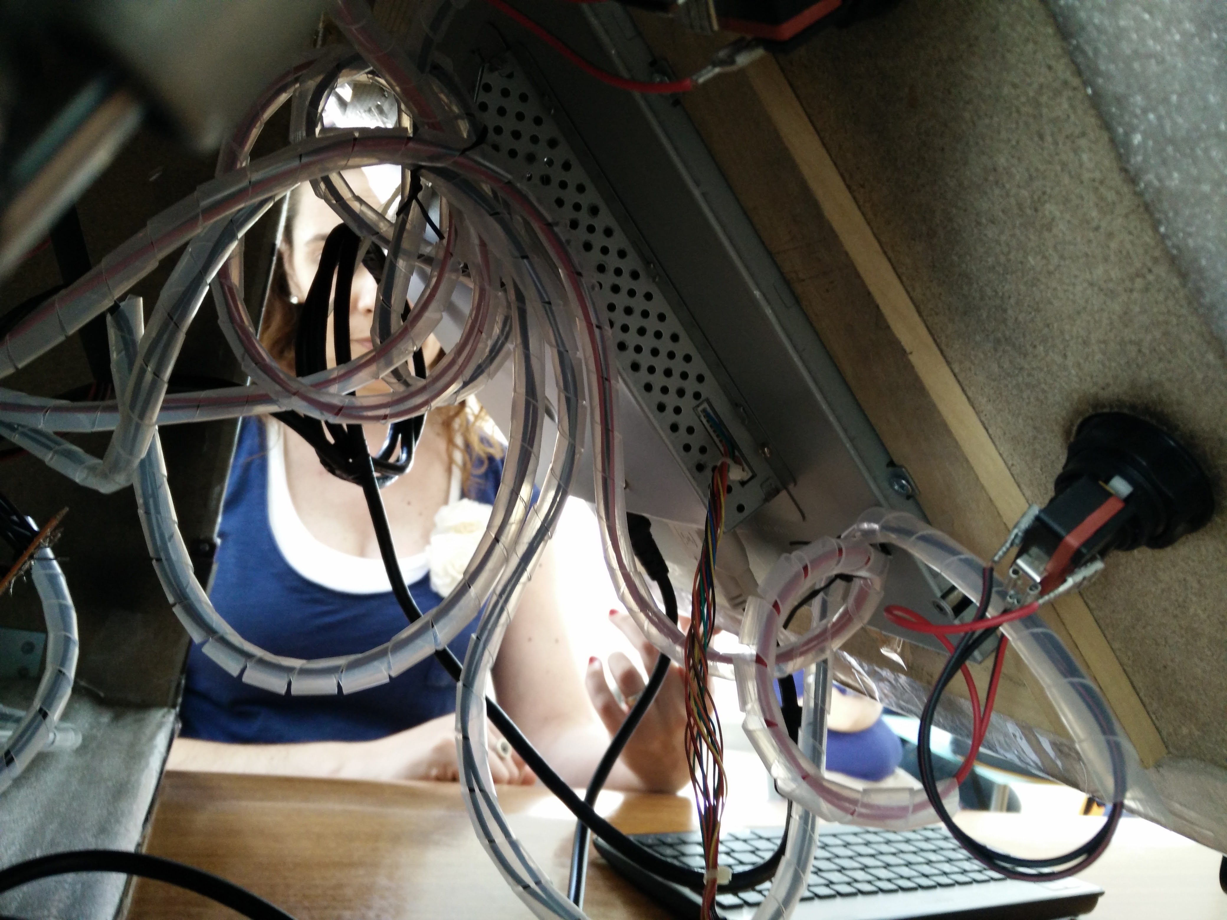
The access to the wiring inside was made by the monitor side, using hydraulic hinges so they could help lifting the monitor .
Camera
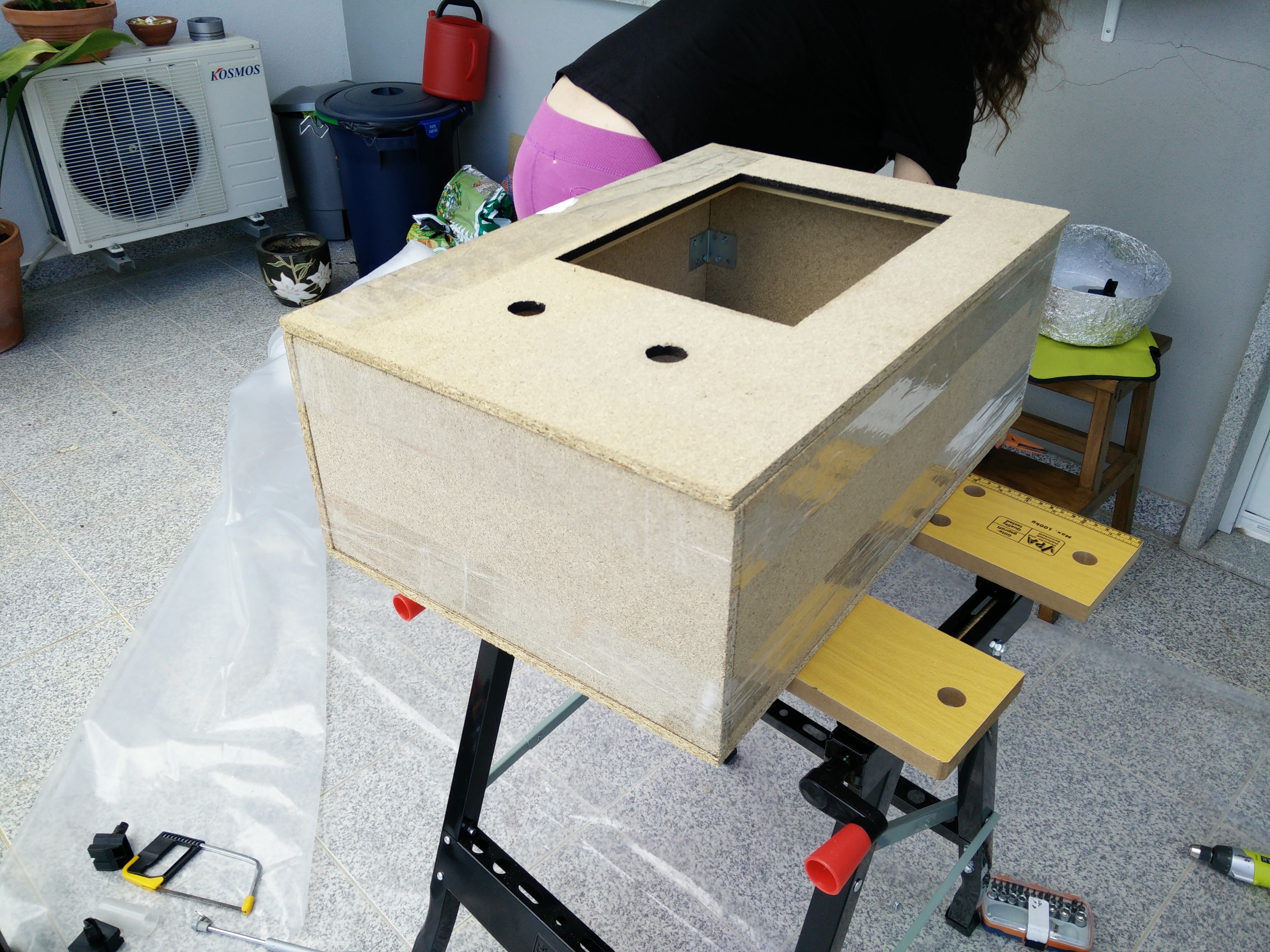
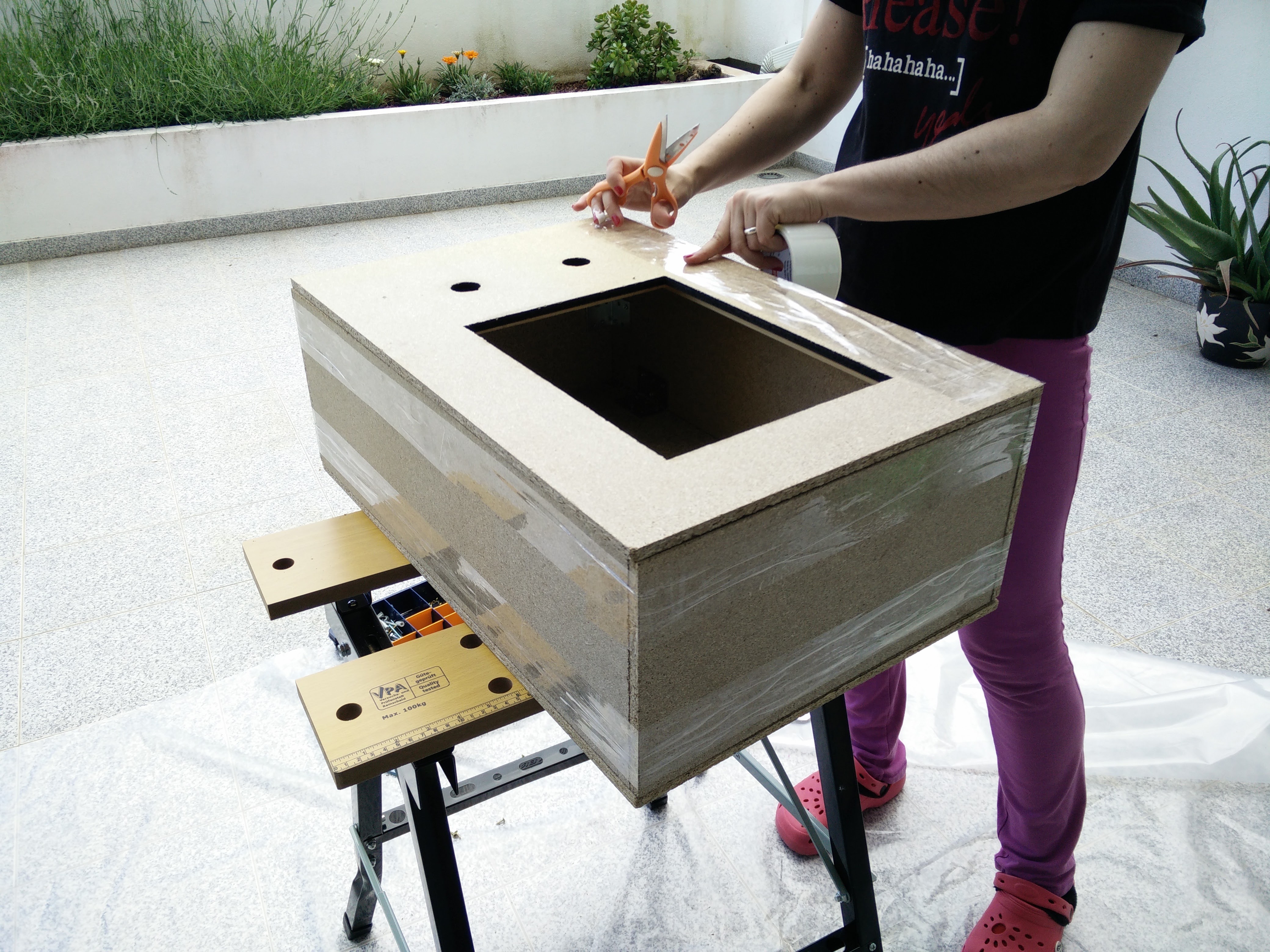
Camera
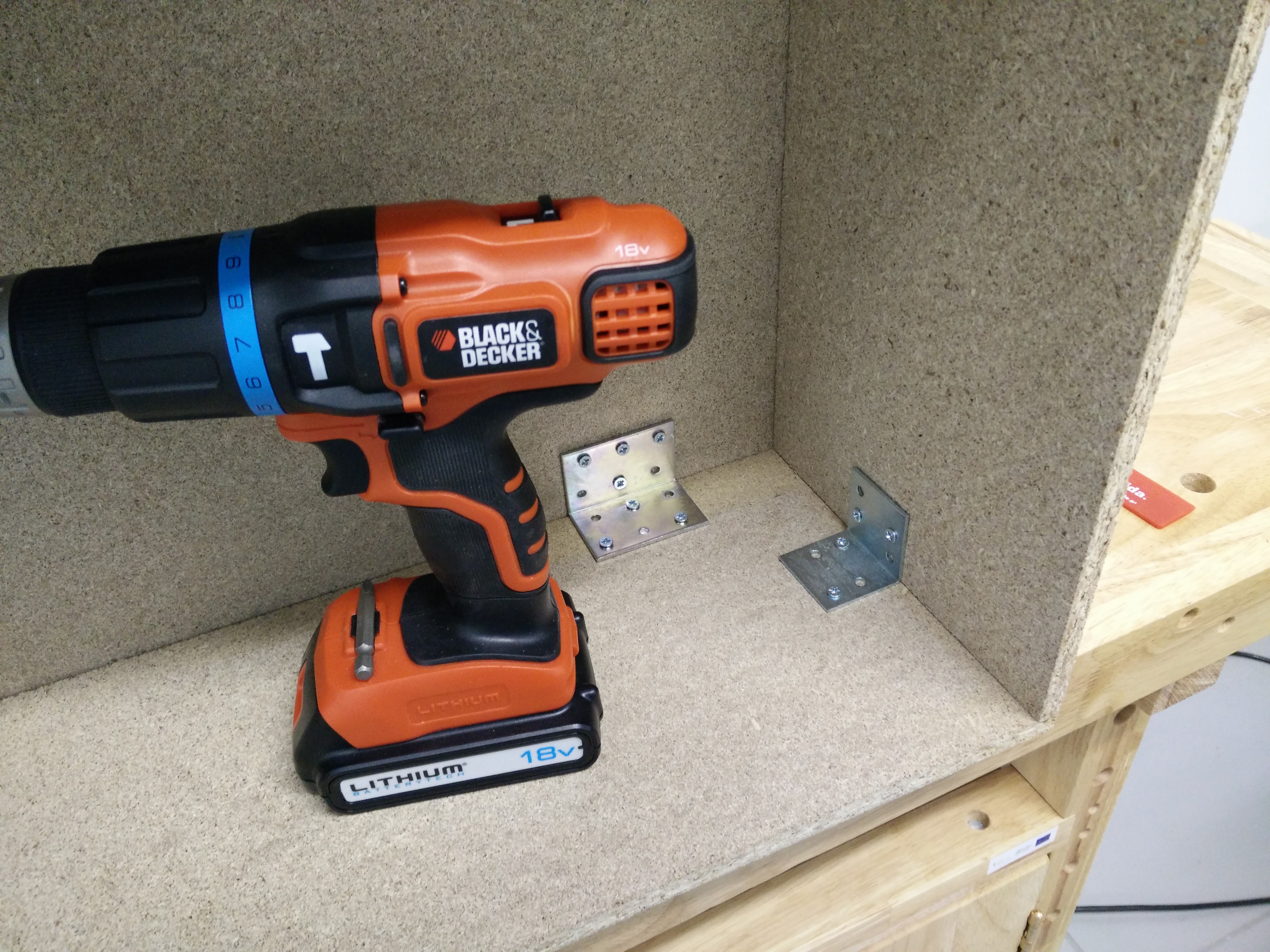
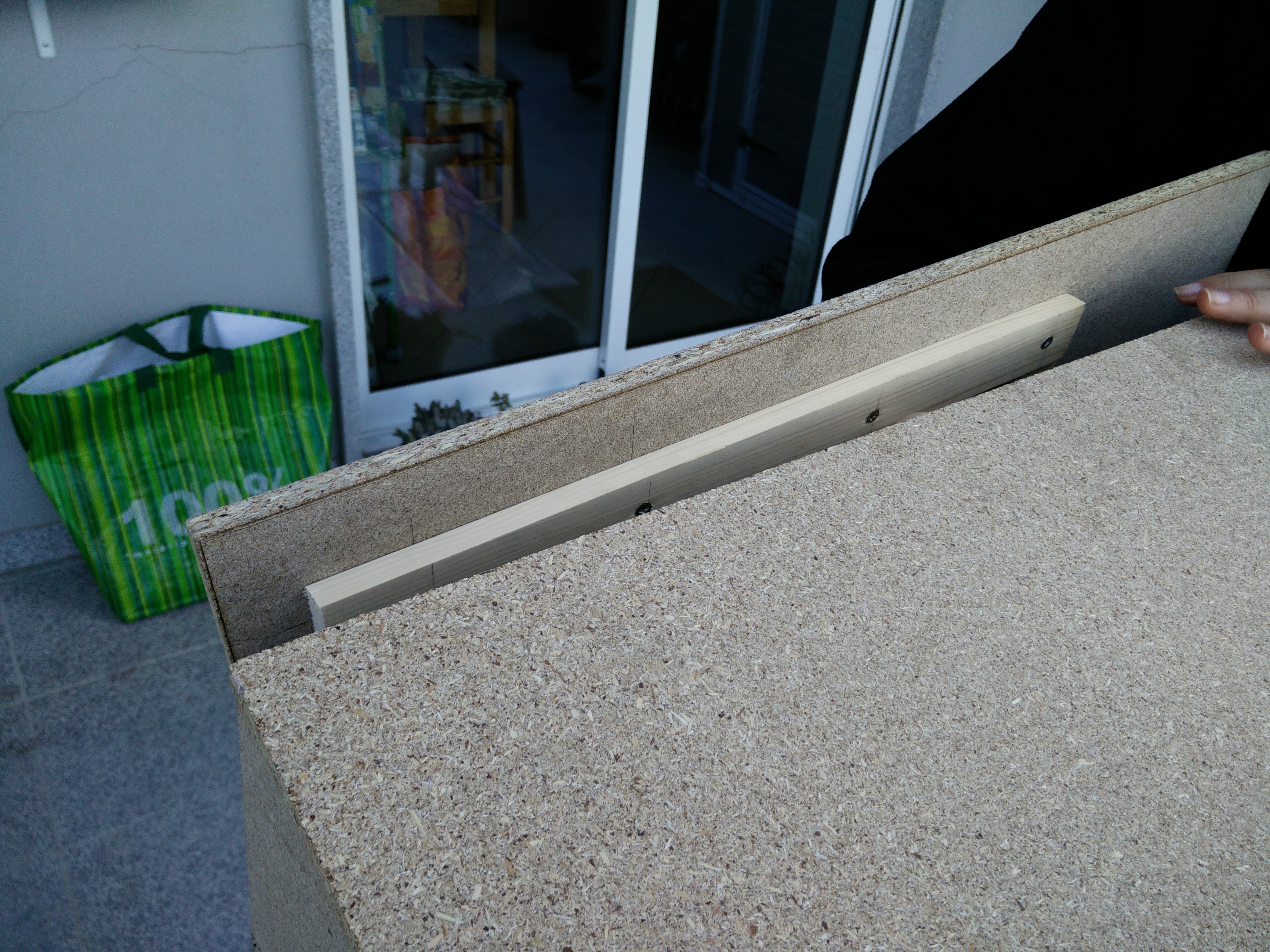
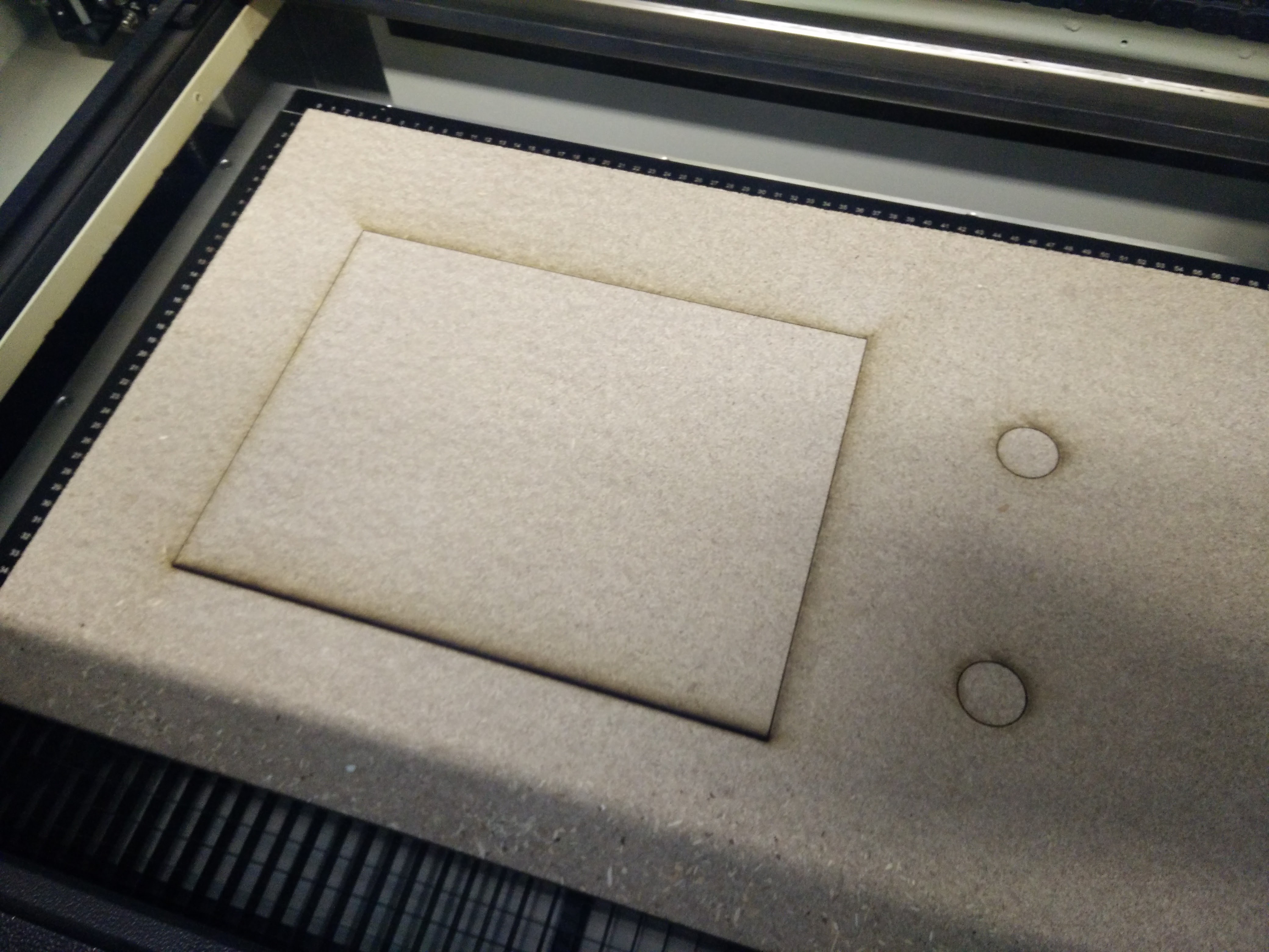
The camera is a box with the following dimensions: 60cm x 40cm x 30cm Yours can be smaller, bigger, it's up to you. Just need to accommodate for the monitor you're going to use. The MDF panels were laser cut at the local Fablab. There's need for 3 holes in the back - two big dome push buttons and one for the monitor. In the front, 2 holes - one for a big dome push button and another one - smaller - for the Raspberry PI camera. I don't have specific measurements - just imagine a camera and use that.
Monitor
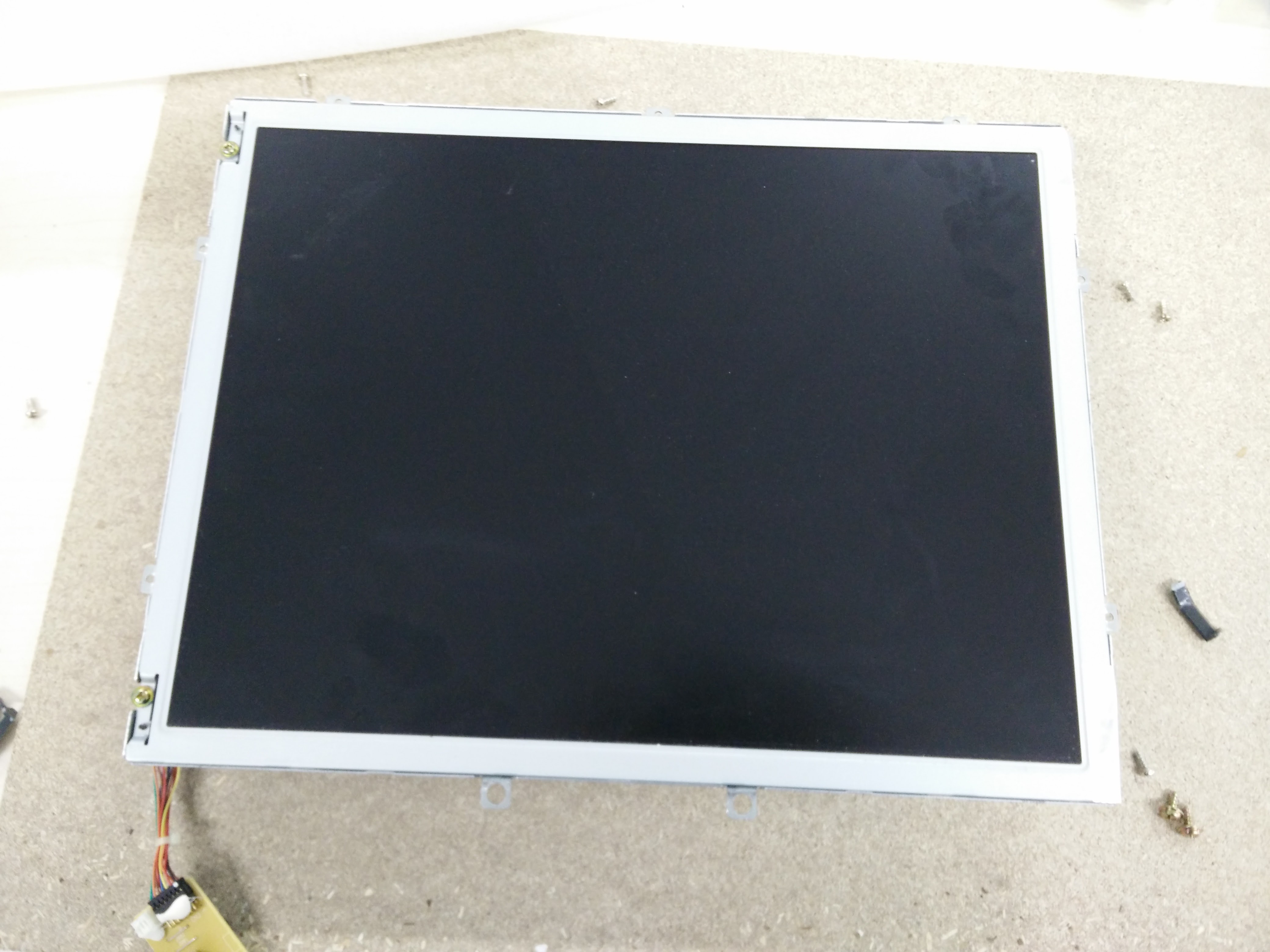
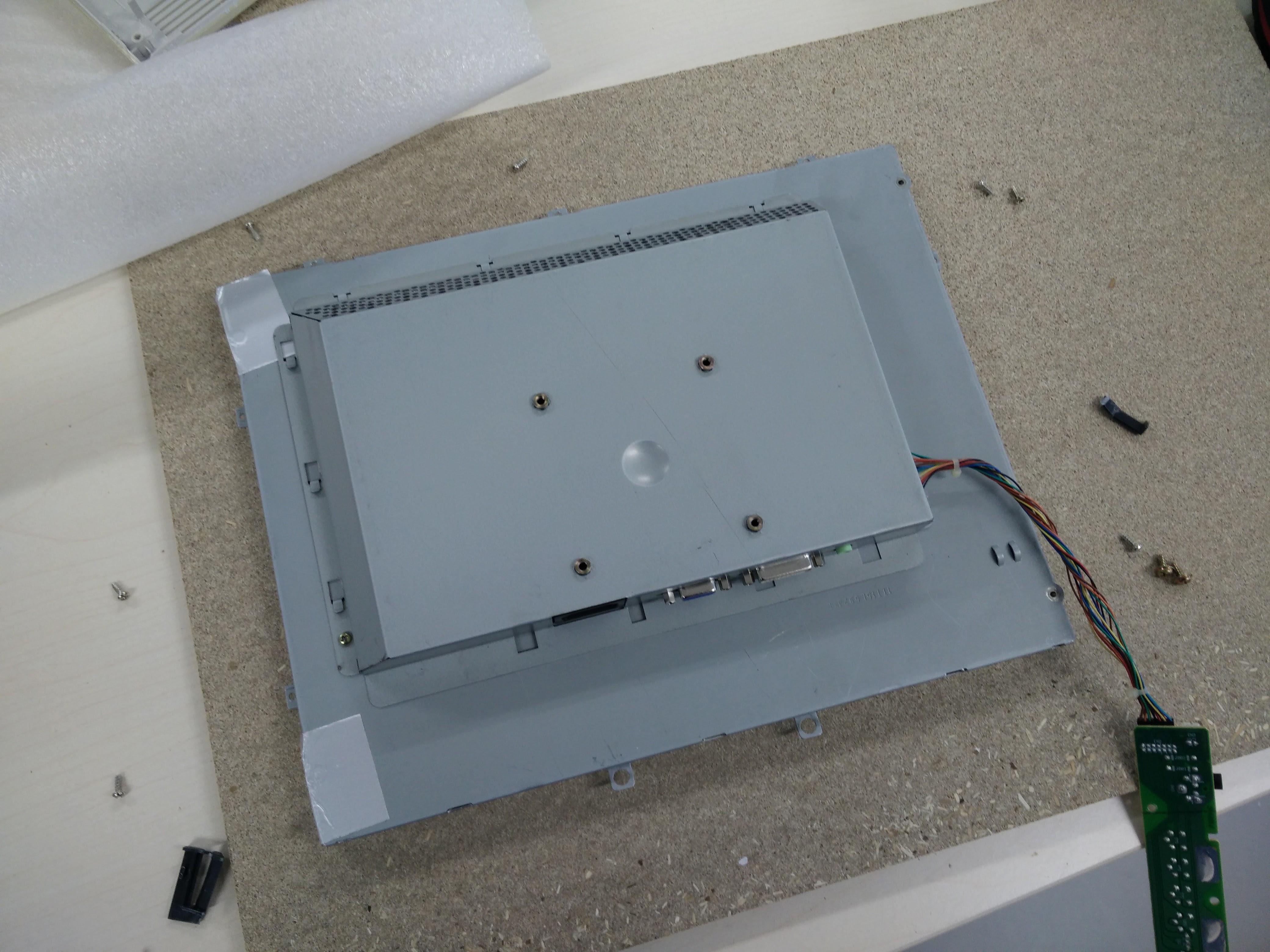
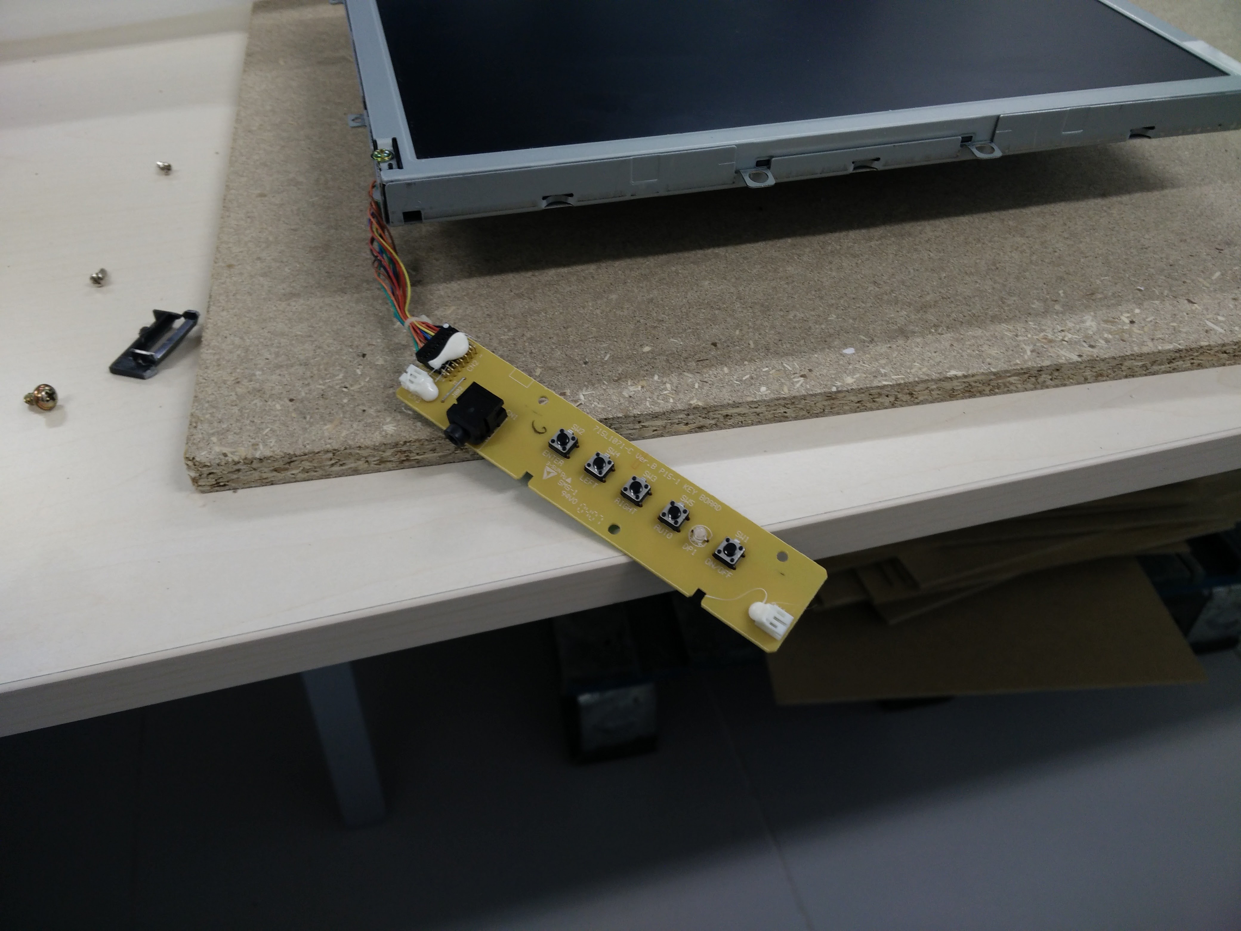
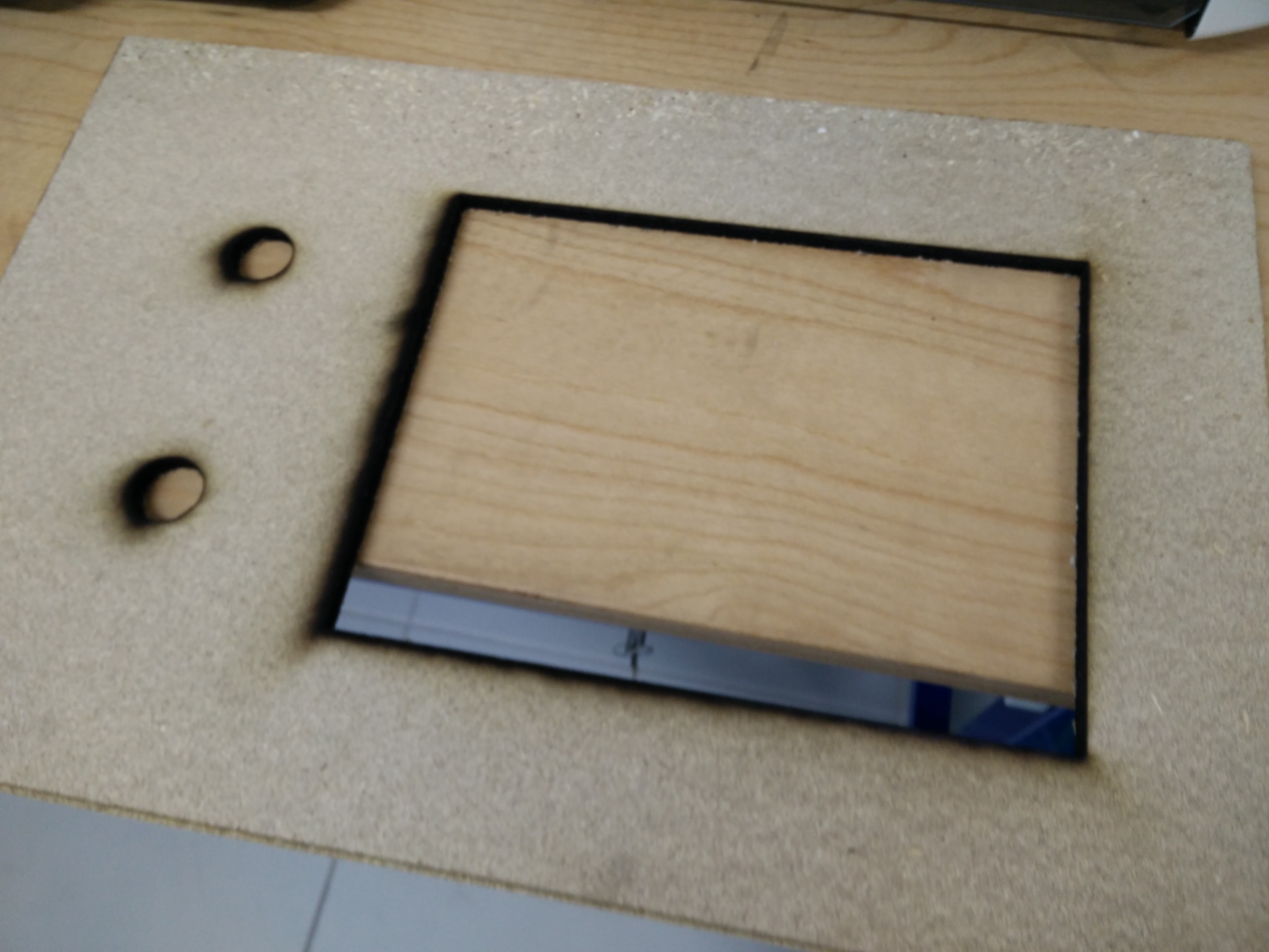
Monitor
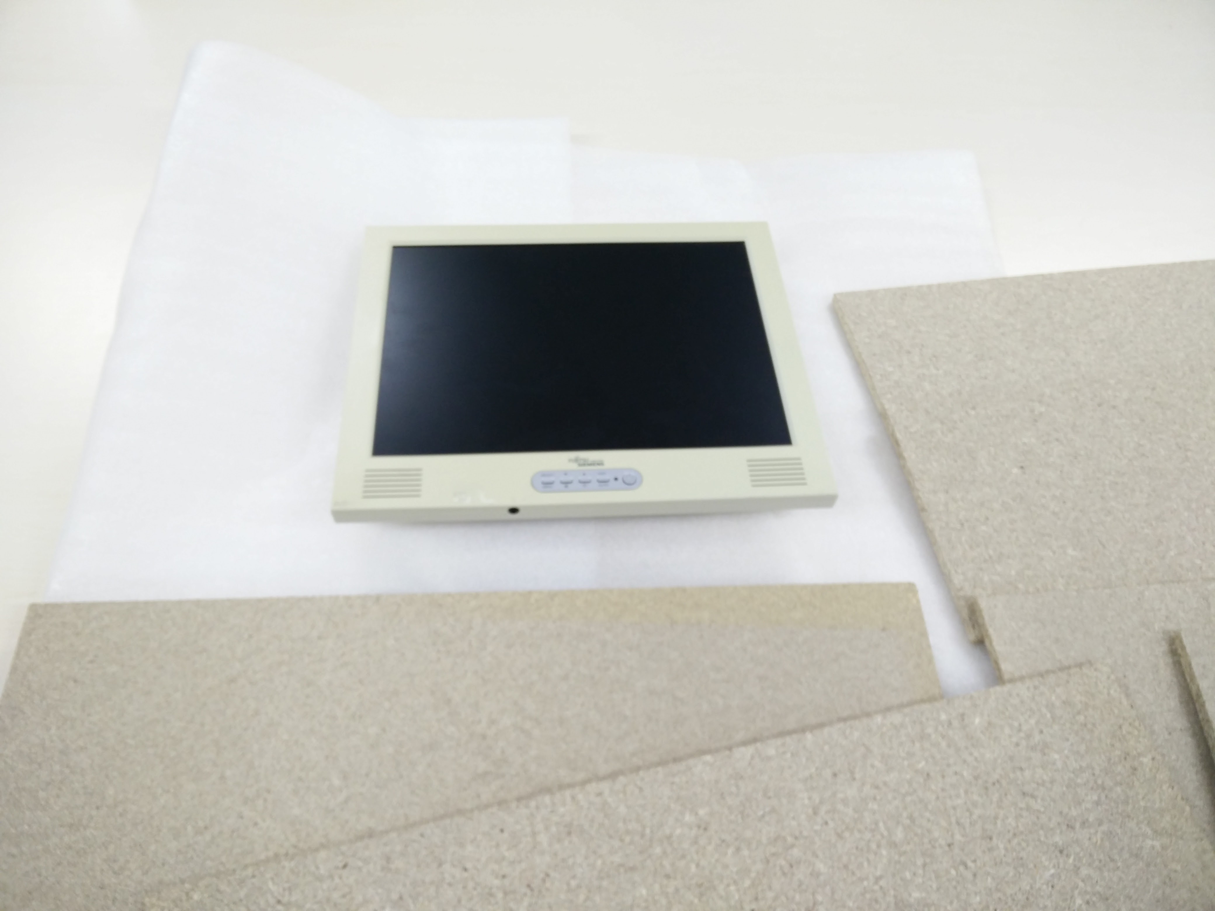
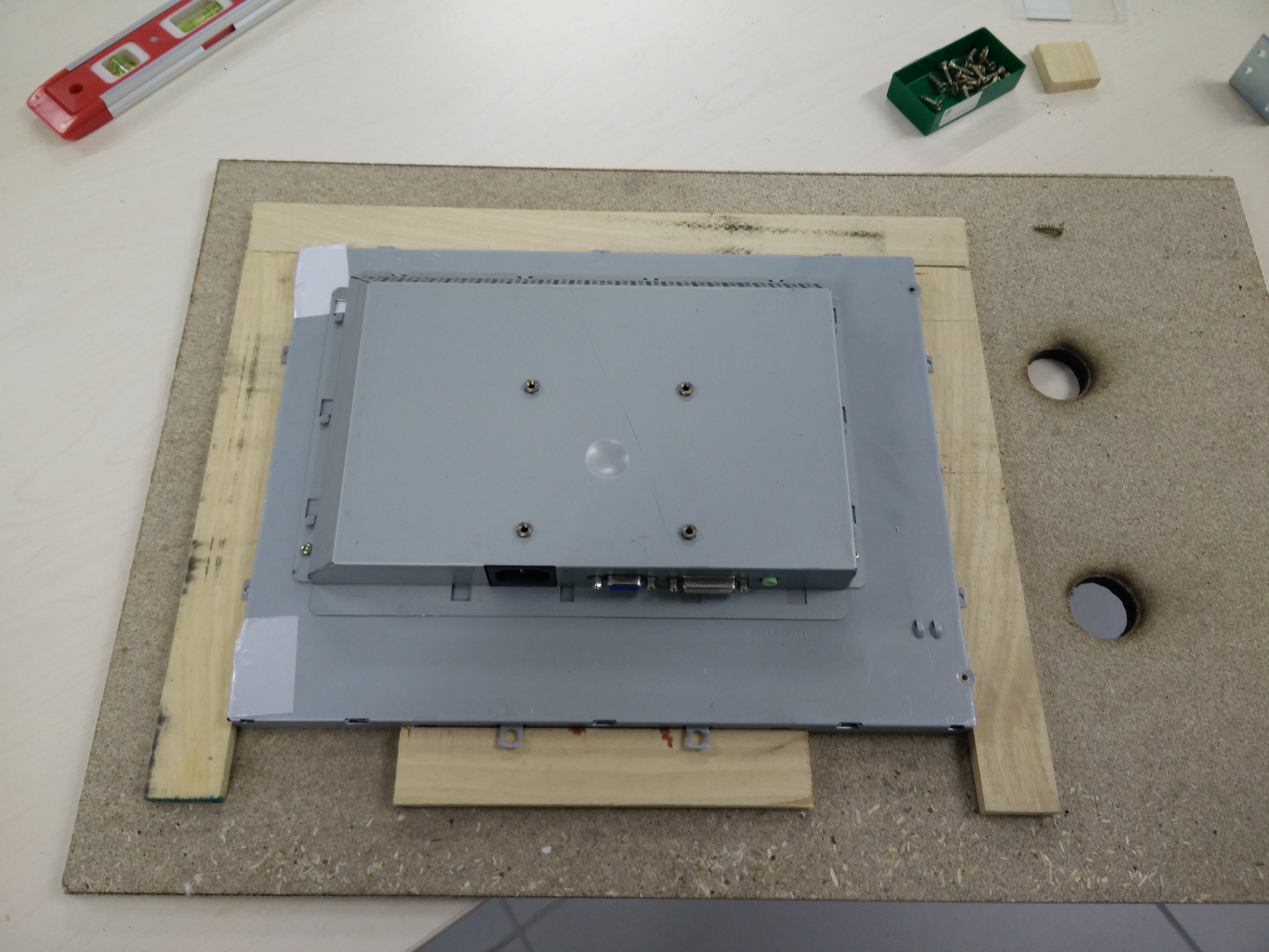
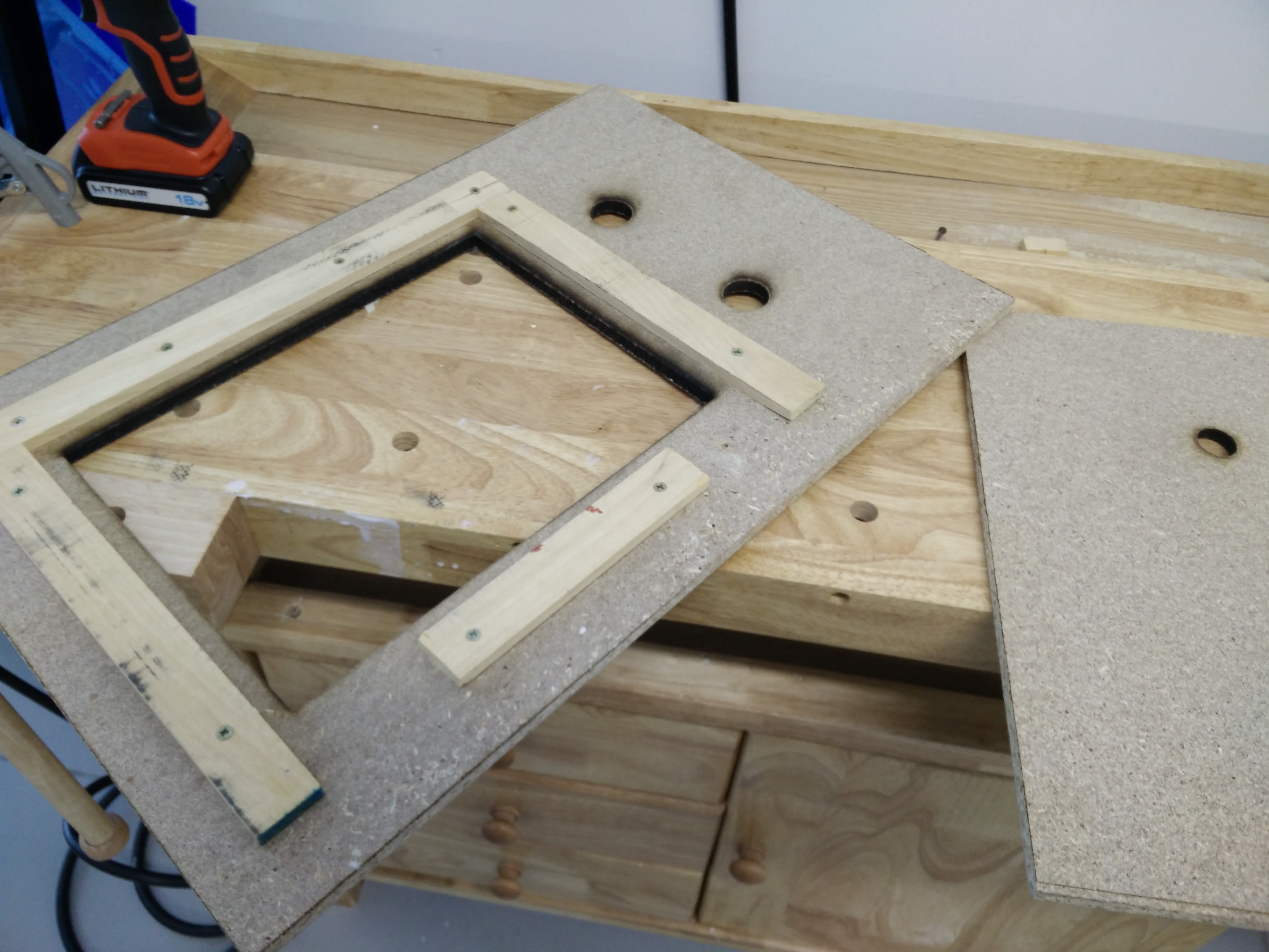
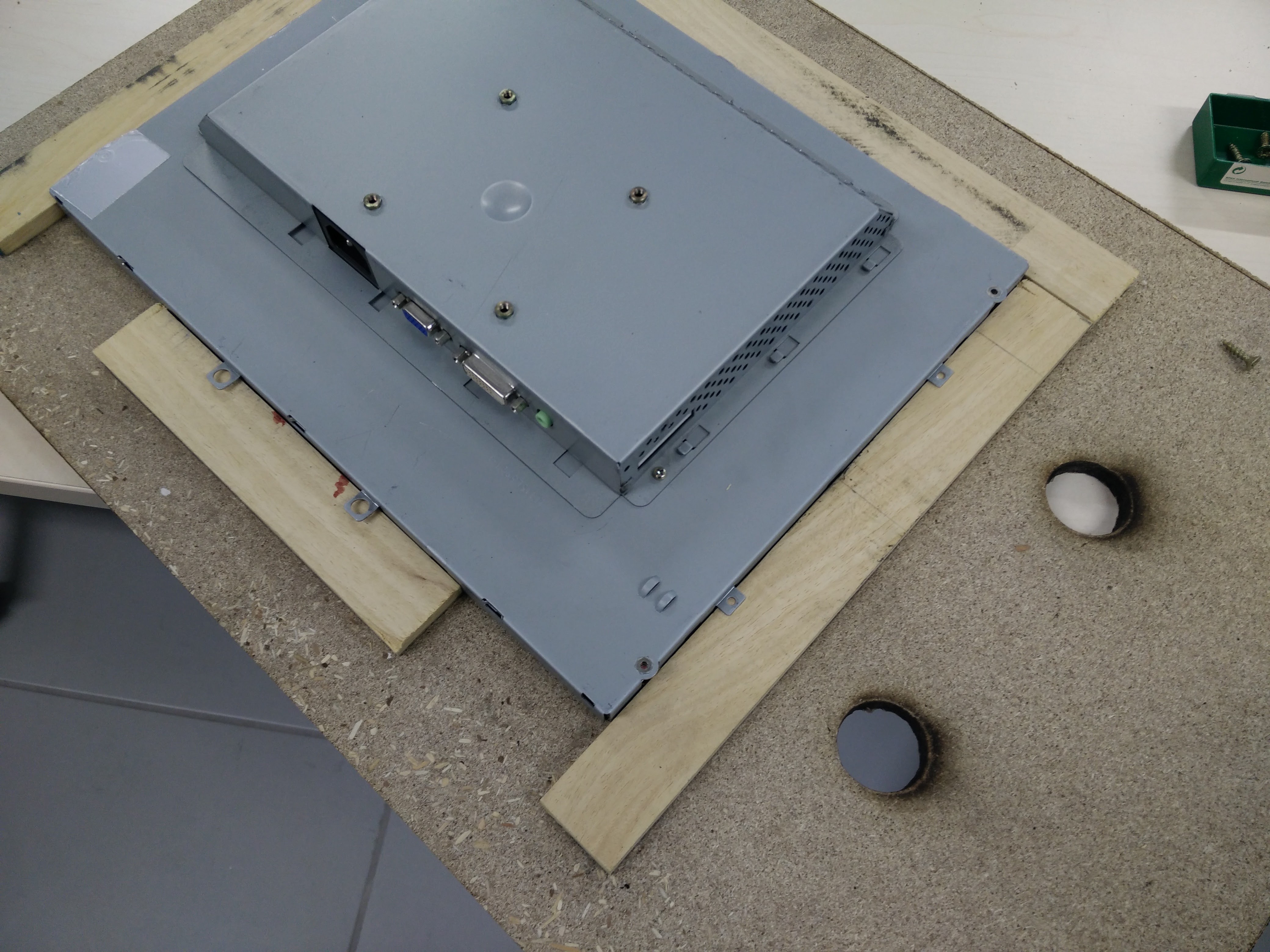
The monitor support was made adding small pieces of wood to support it within it's dimensions.
It was strip from the plastic housing and secured in place with screws. To help lifting it, two hydraulic hinges (used) were used.
Decorating
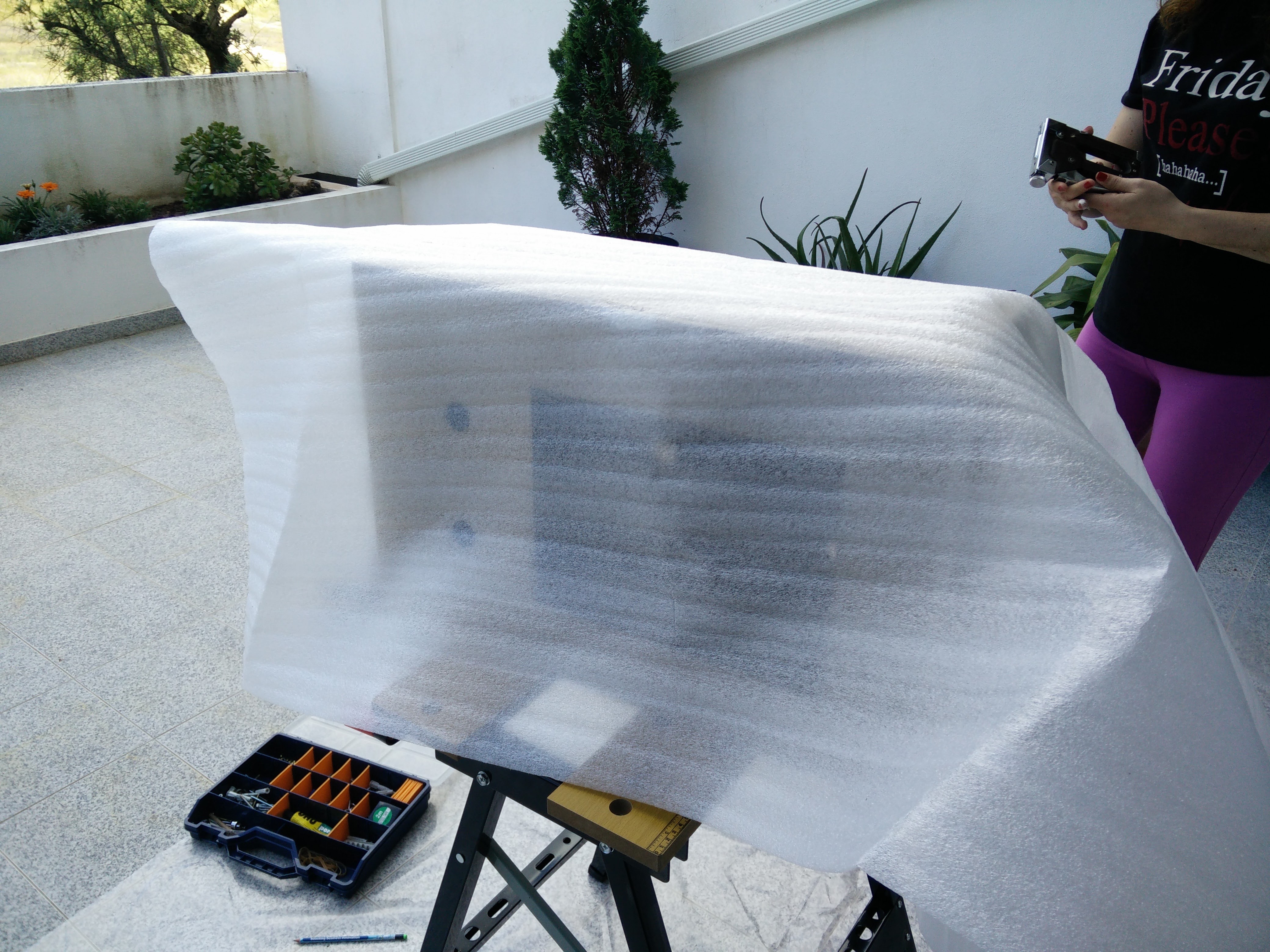
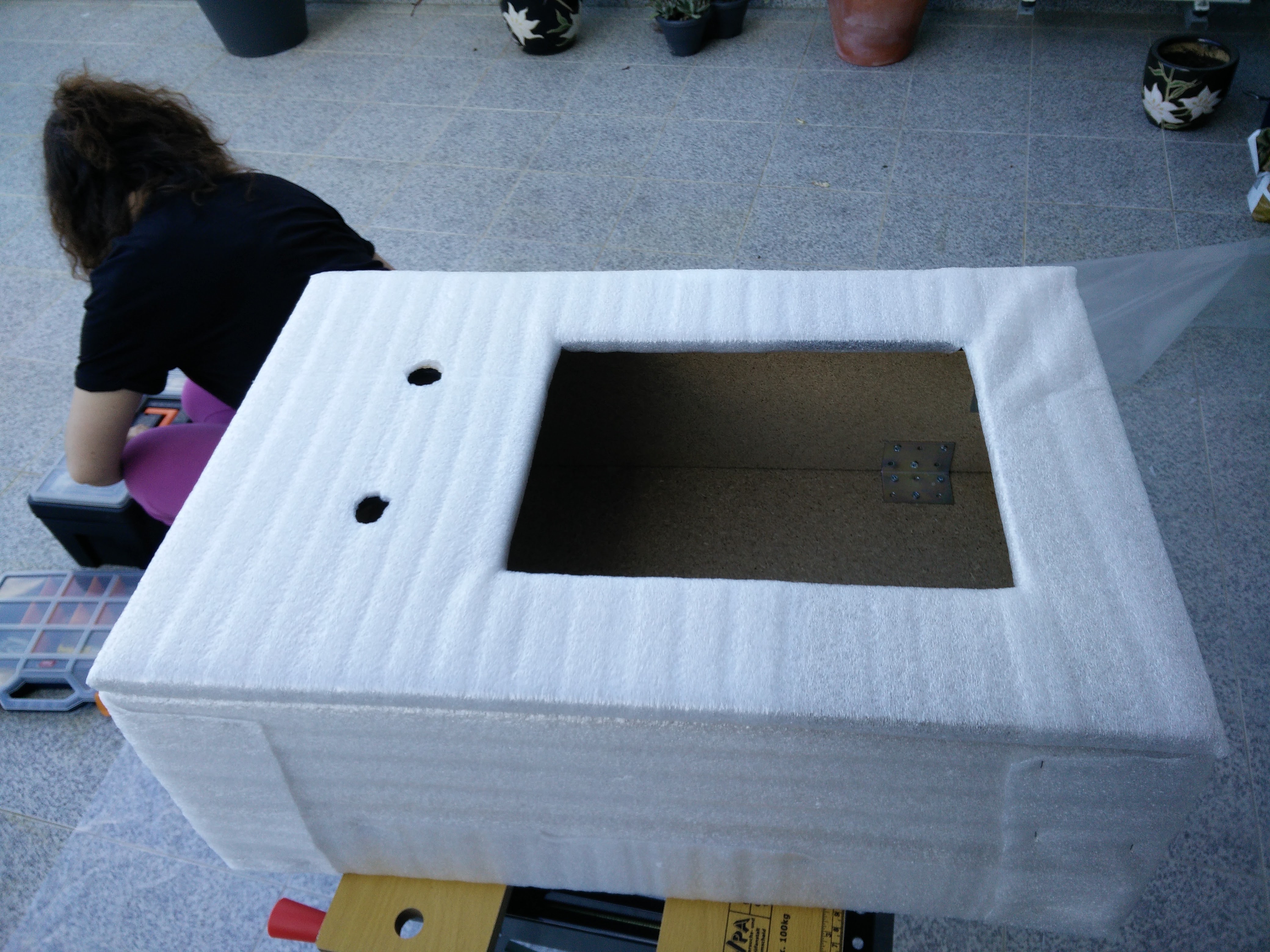
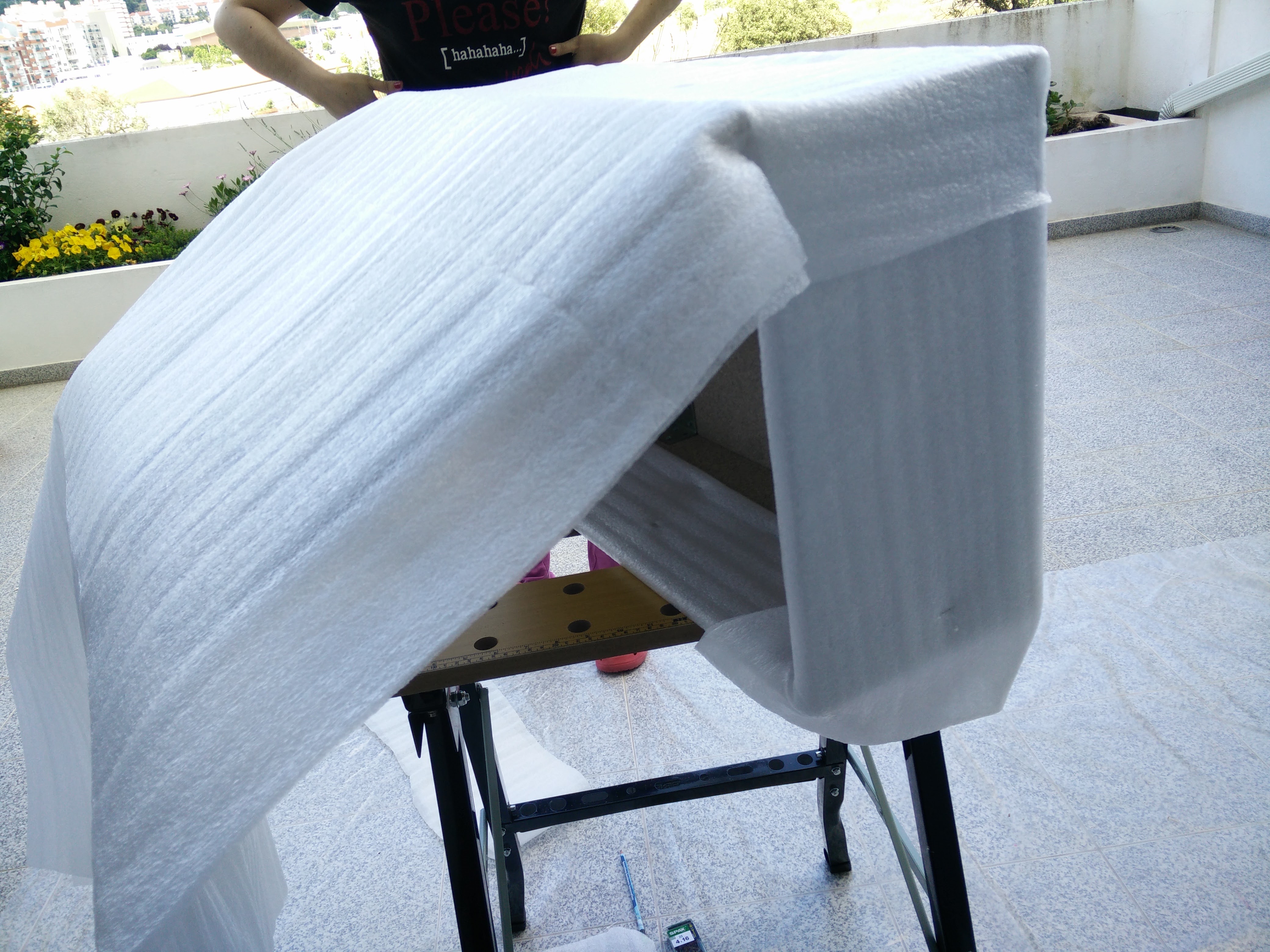
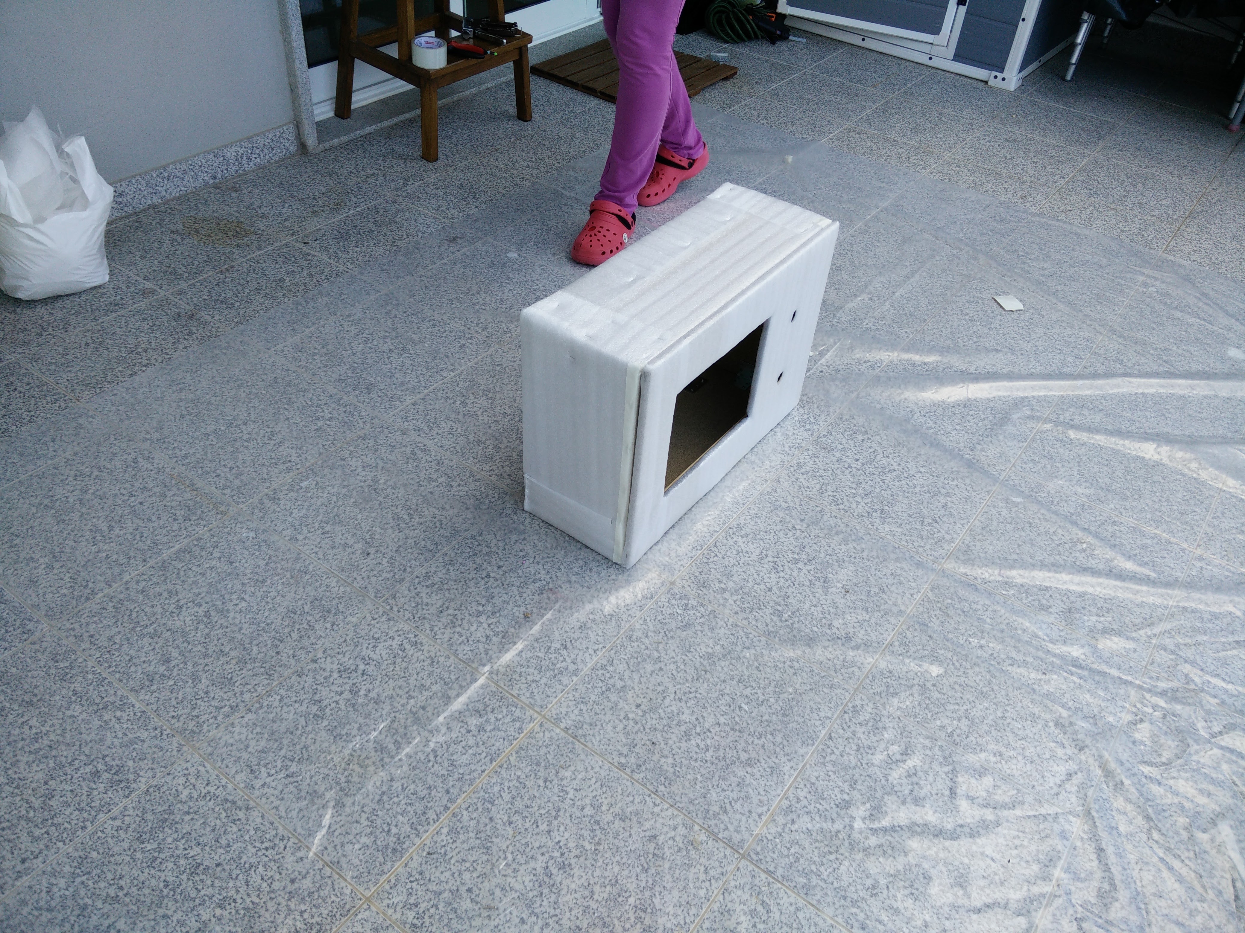
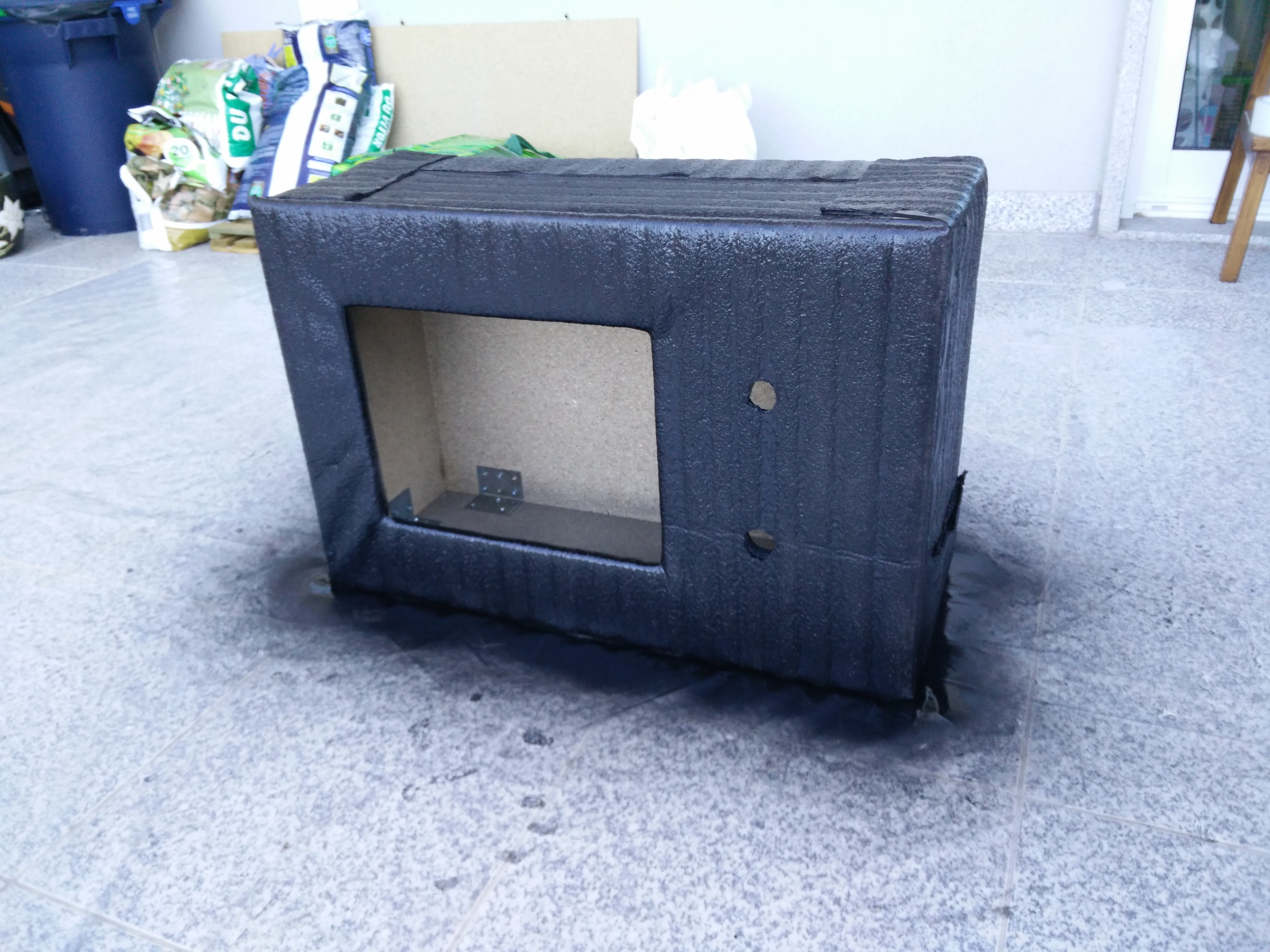
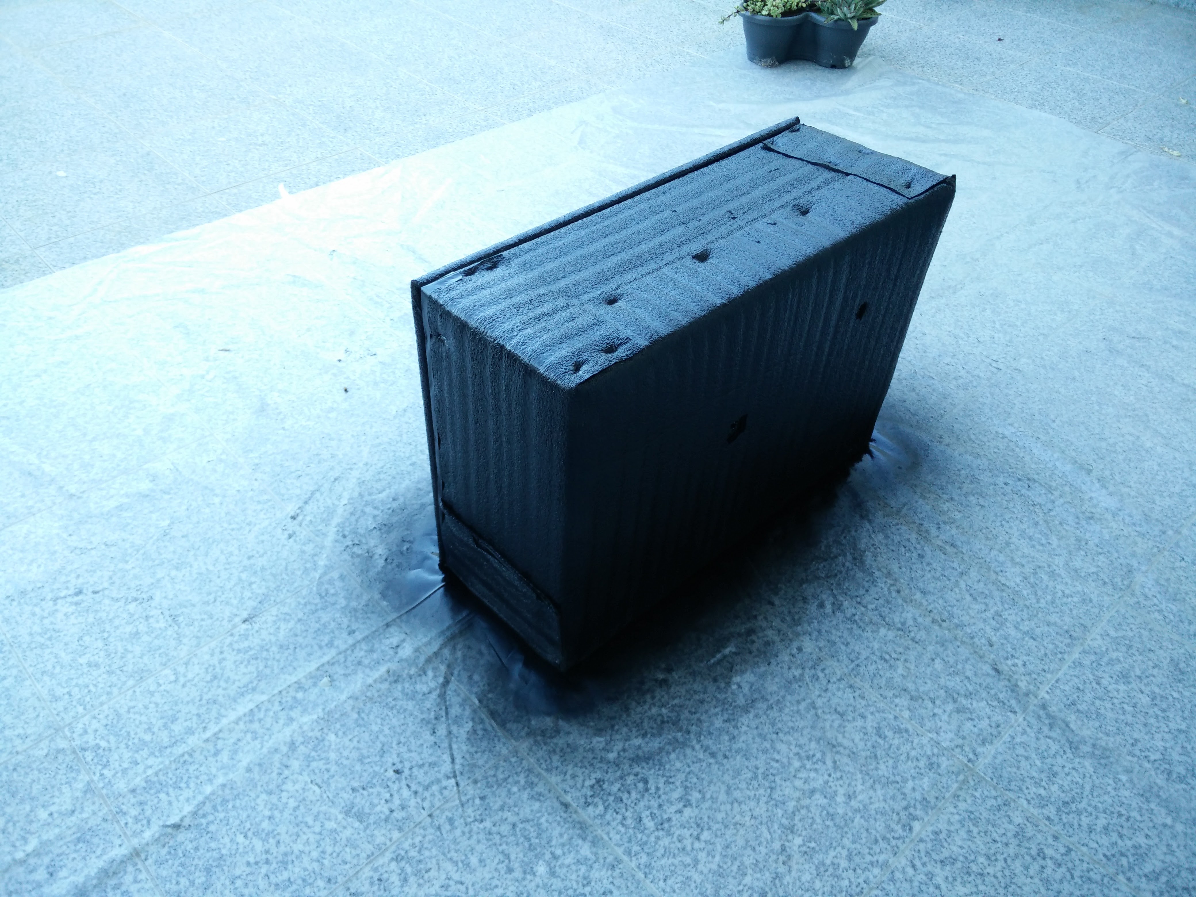
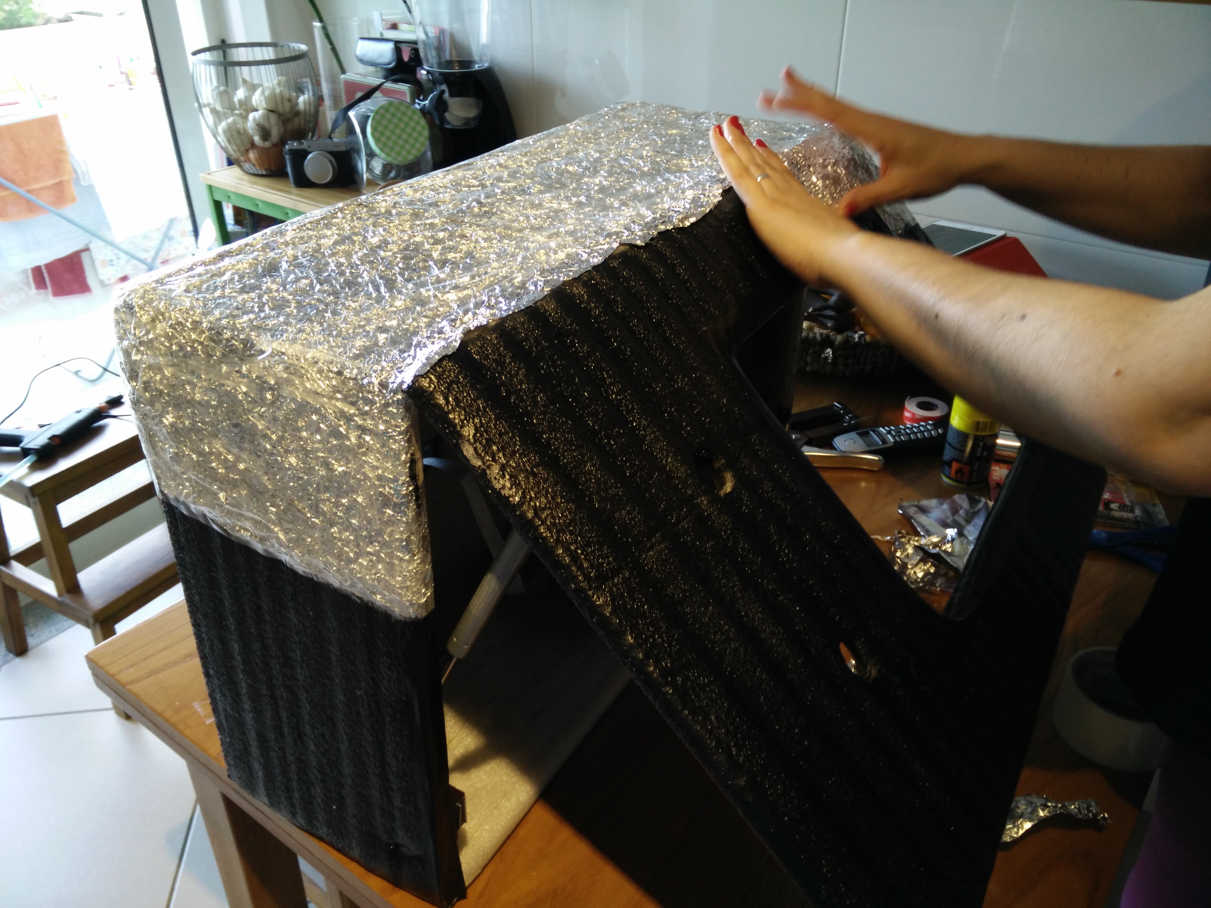
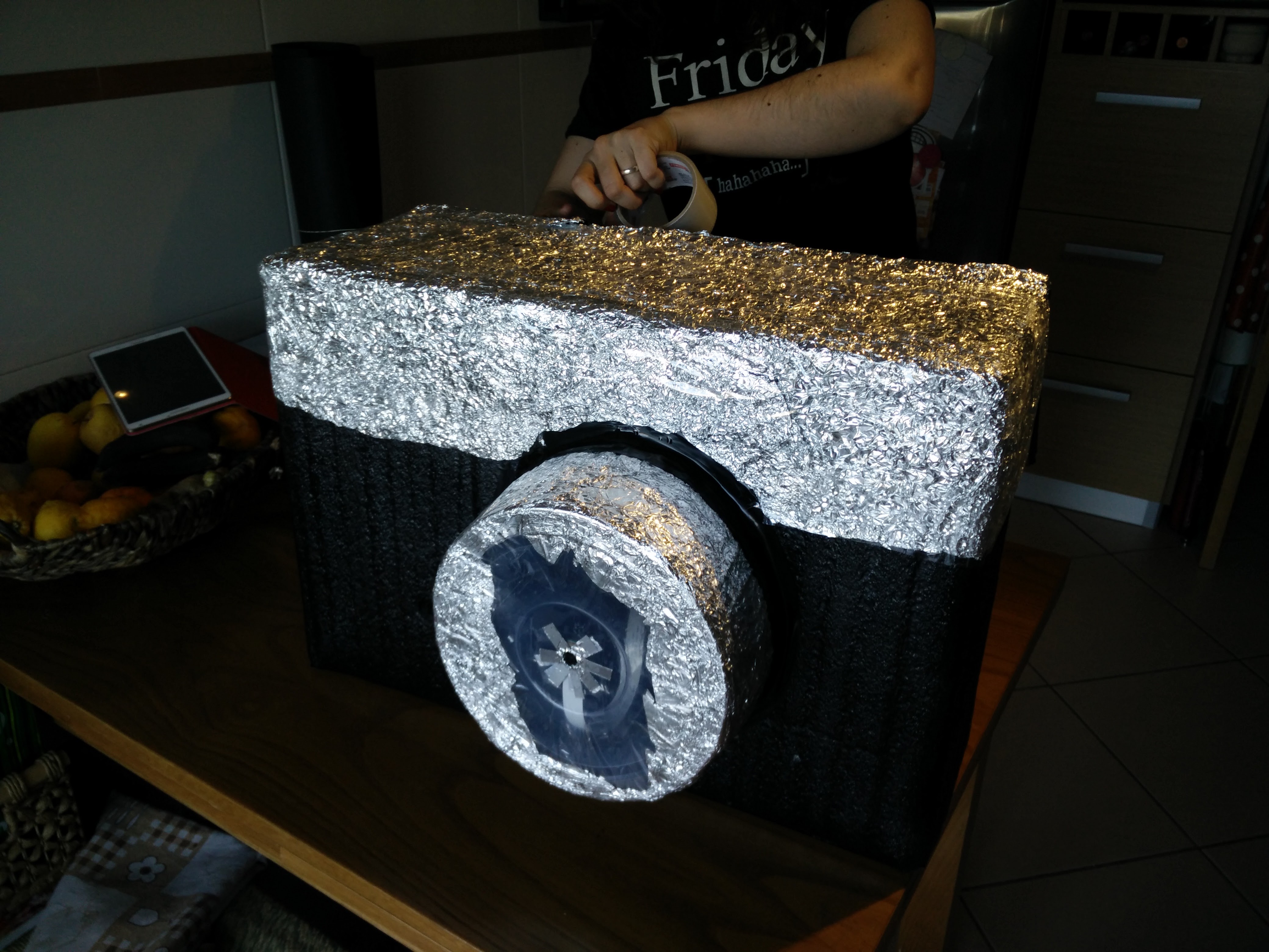
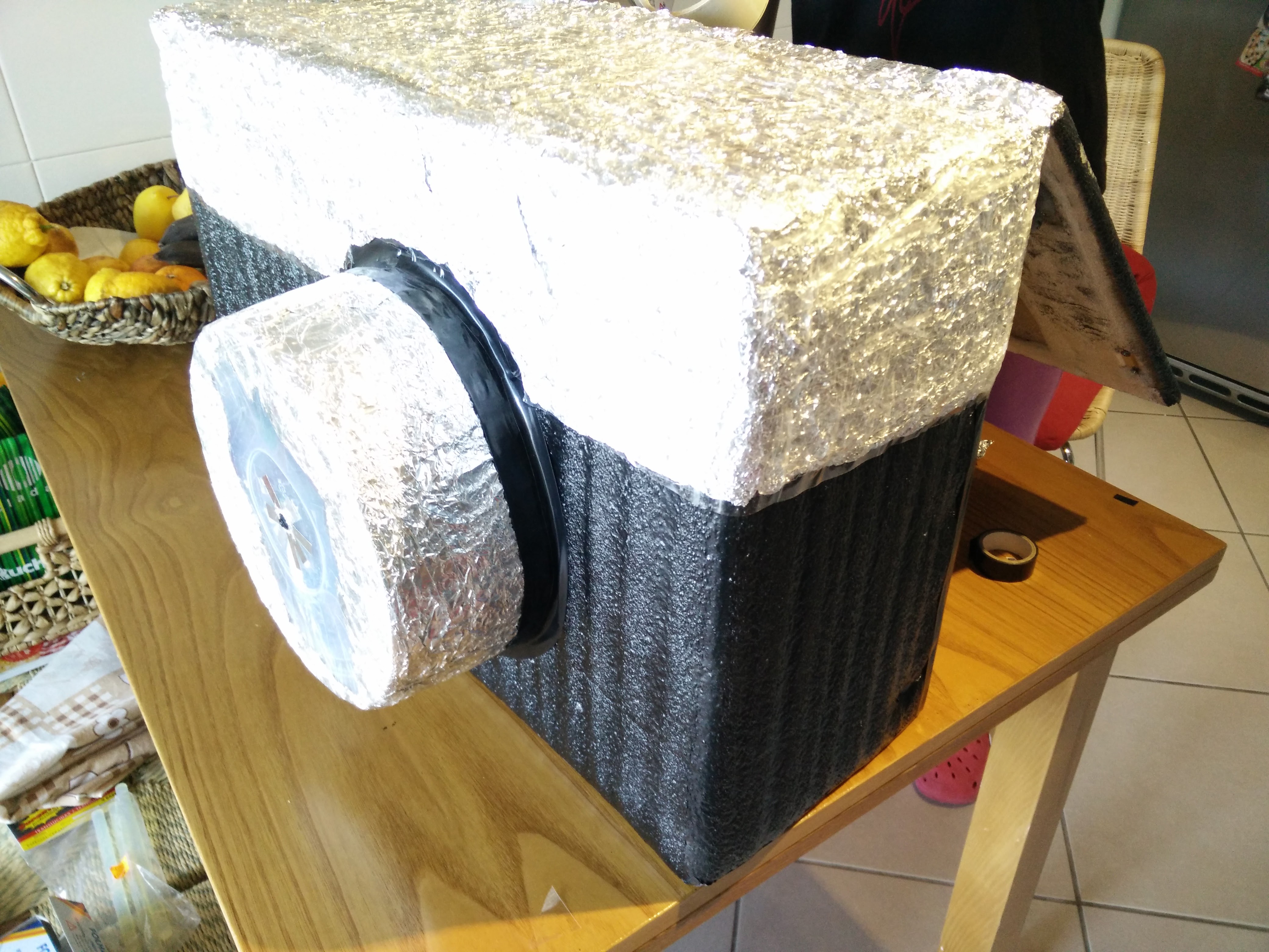
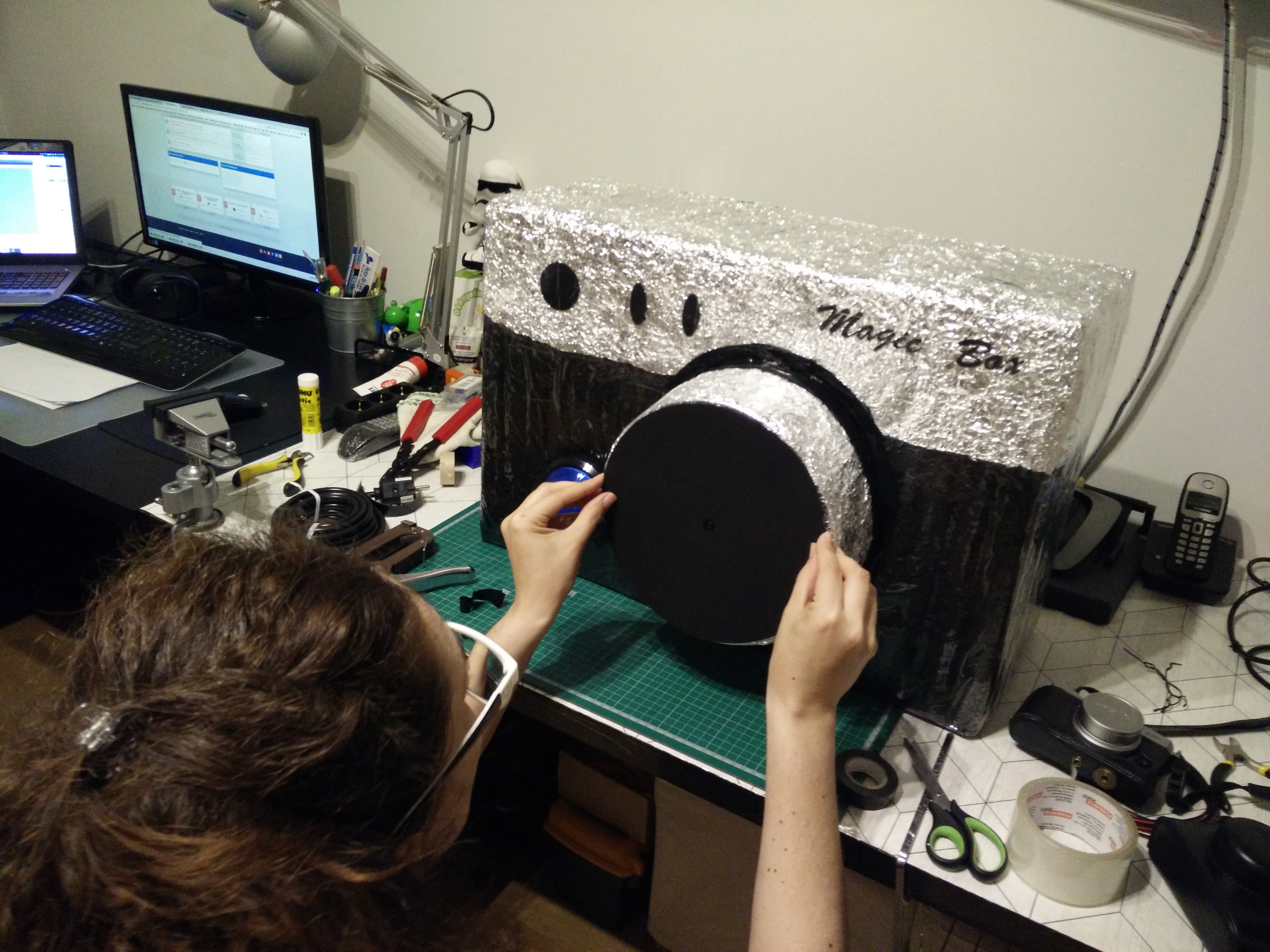
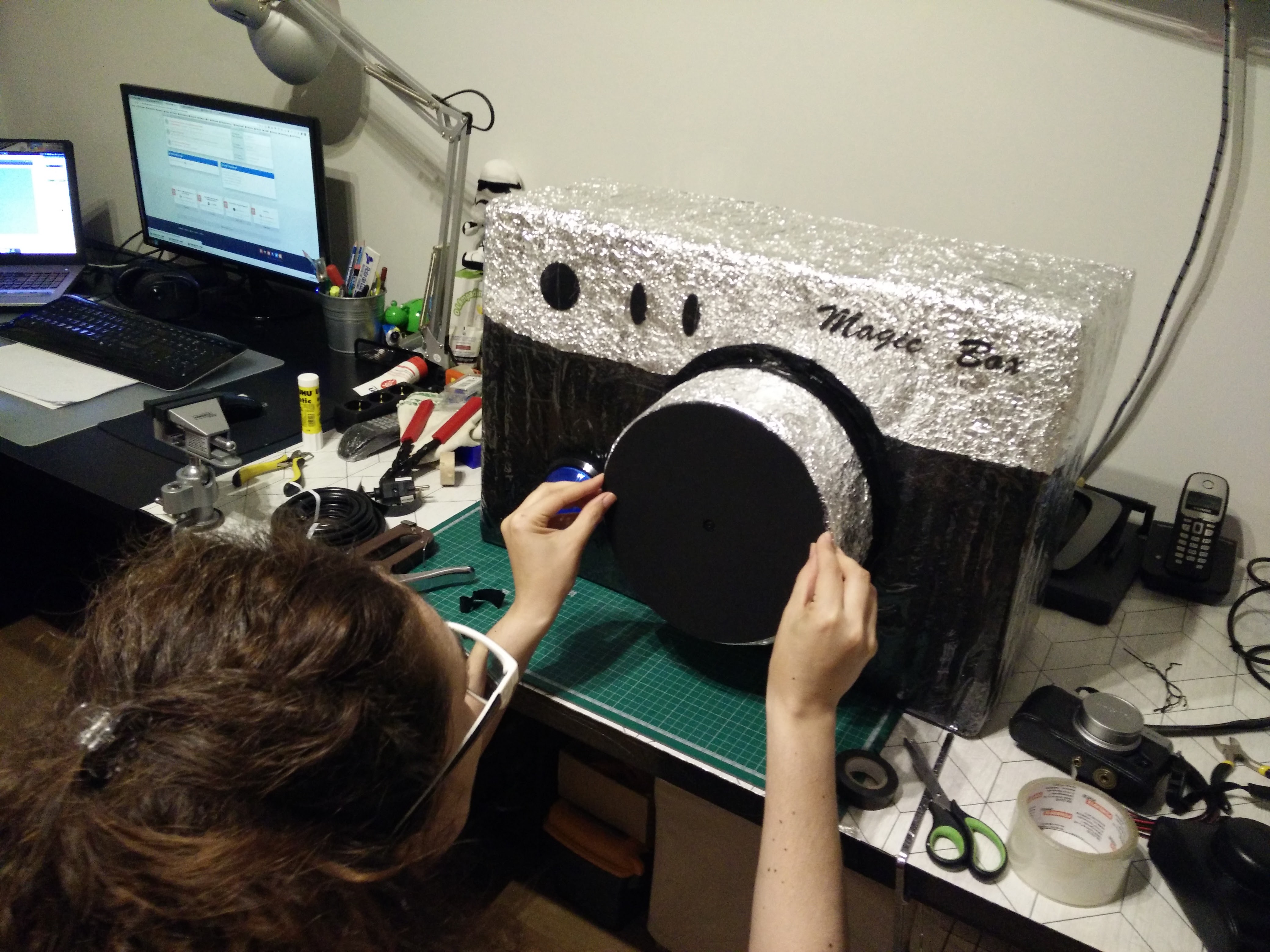
Since I like a lot the style of my Fuji X-T30, we went and did something similar.
First, we covered it with foam and next we spray painted it black. After the paint, we added aluminum foil for the silver parts and wrap it in
To simulate the lens, we just used a round Tupperware were we did a small hole for the Raspberry PI camera module to sit.
Programming
Programming the Camera was a challenge, but it was super fun.
There's no GUI - this runs on the CLI and it runs on Python version 3 .
I first started by testing and programming the buttons, next was taking pictures using the tools already provided and the Python API. I then moved on to overlay pictures in the camera output (for the countdown) and next to interact with Twitter and Facebook.
After I was comfortable with all that, like a puzzle, I assembled all the pieces together. In here, we're going with the same process. Start slow and small and go to fast and big.
First, let's start by configuring the Raspberry PI
Preparing the Raspberry PI
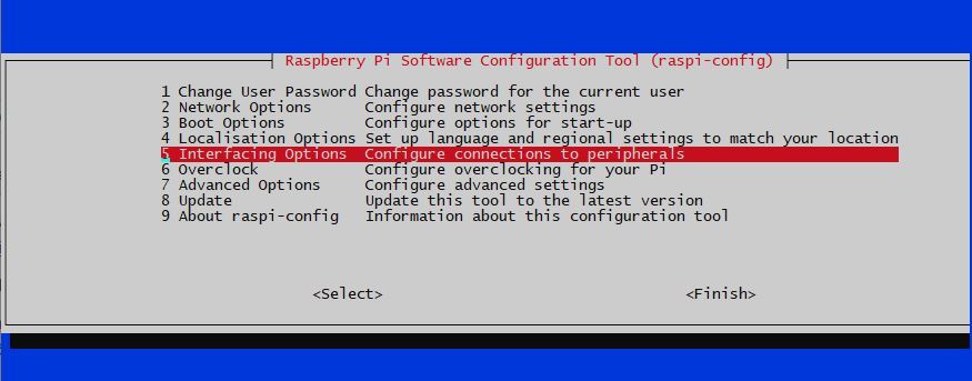
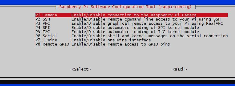
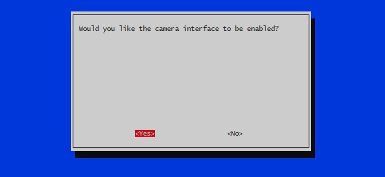


I'm not going to explain how to install Raspbian on the Raspberry PI - there's a lot of tutorials out there, even on the Raspberry PI official website.
You just need to have SSH access to it, or plug it to a monitor and plug in a keyboard and mouse.
NOTE: When starting with the Raspberry PI camera, you need to have it plugged in to a monitor. Until there, all the steps can be made using SSH.
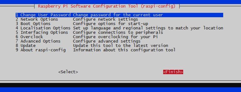
After booting in your Raspberry PI, we need to enable the Raspberry PI camera. Let's use raspi-config tool for that.
sudo raspi-config
- Choose option 5 - Interfacing Options
- Choose P1 - Enable/Disable connection to the Raspberry PI camera
- Say Yes
- for OK
- Choose Finish
- Choose Yes to reboot now
After the reboot, we can proceed
Software
We're going to need some Python libraries to be installed. This has been updated for the latest Raspbian version - Buster
First, lets set Python 3 as the default . Follow this link to know how to set it up SYSTEM WIDE
Libraries:
- python-pil.imagetk to manipulate images
- python-rpi.gpio to access the GPIO PINS
- python-picamera to access the Raspberry PI Camera
- Tweepy to share the photo to twitter
- facebook-sdk to share to a facebook page
sudo apt-get install python3-pil.imagetk python3-rpi.gpio python3-picamera python3-tweepy python3-pip
Use Python pip to install facebook-sdk
sudo pip3 install facebook-sdk
Programming - Camera Preview
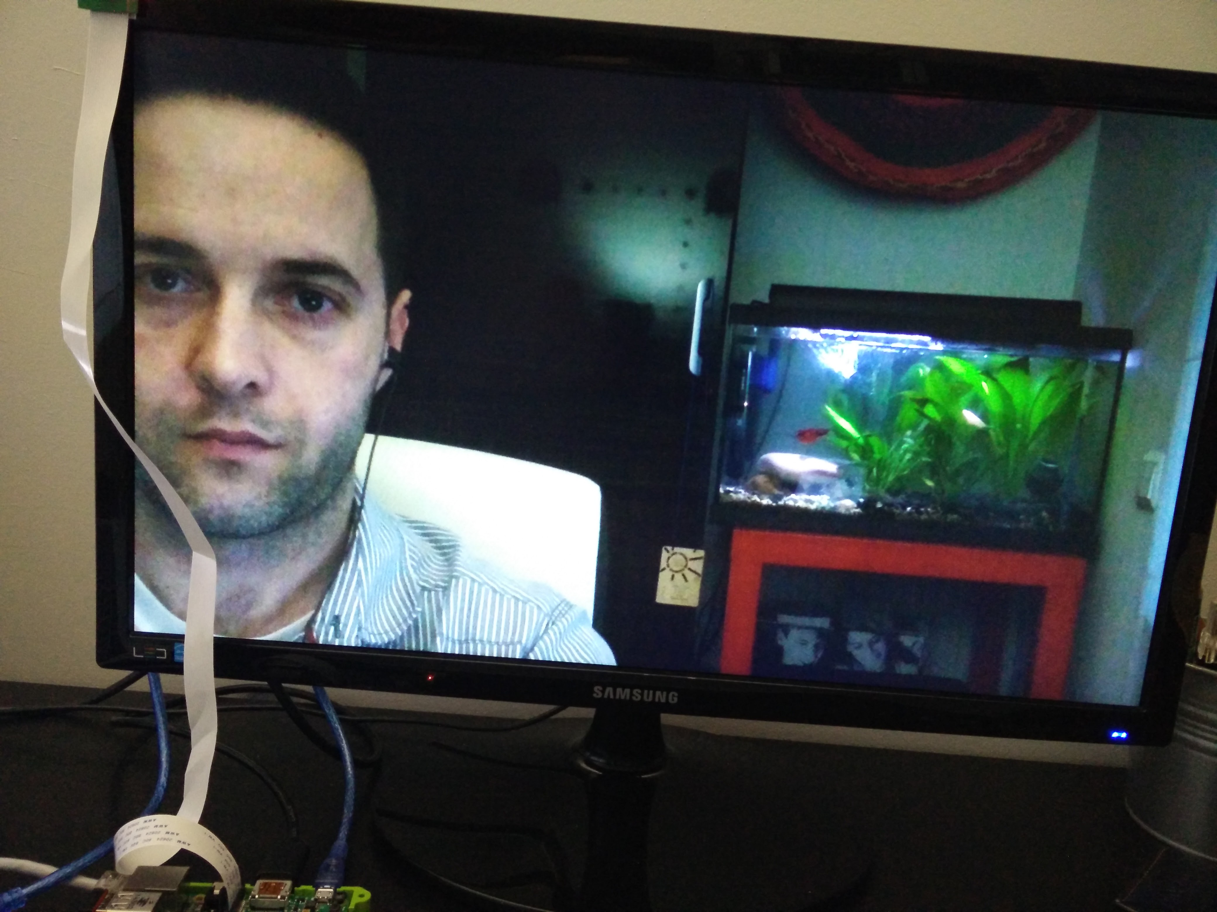
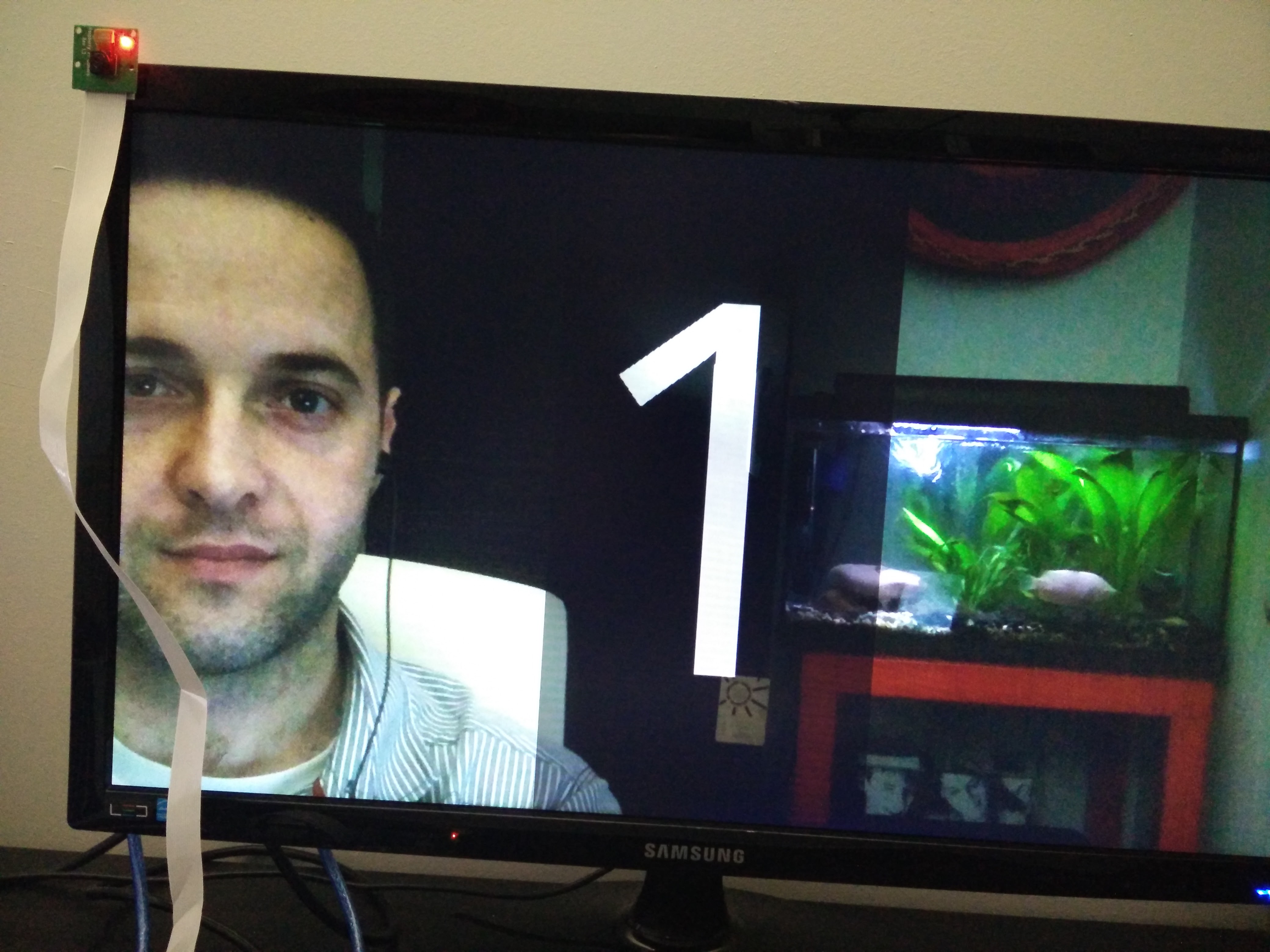


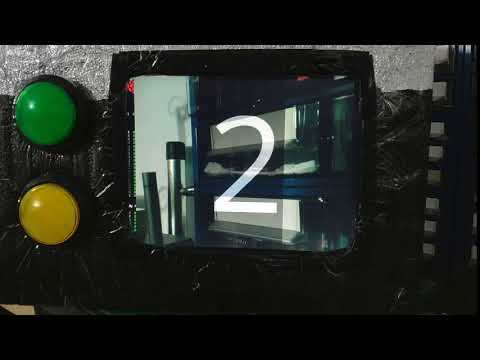
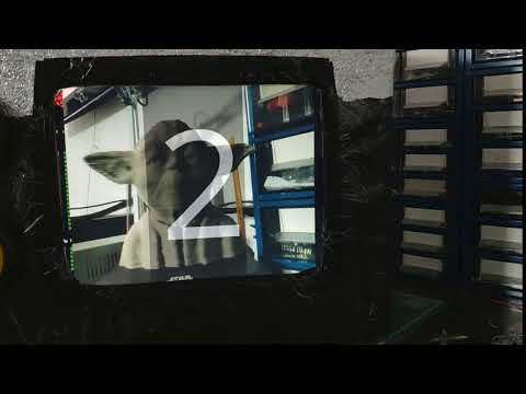
One of the requirements I set to this project was that this program was to run in CLI mode. So, we need to display the camera image on the console. For this, let's use Python Picamera. After that, let's use pil.imagetk to display a overlay on top of the camera preview
Our small program (we're going to develop small programs until one big at the end) will display the camera preview.
#!/usr/bin/env python

import time
import picamera
from time import sleep

camera = picamera.PiCamera()

# Set the resolution you want
camera.resolution = (1280,1024)
camera.framerate = 24
camera.start_preview()
try:
    while (True):
        sleep(1)
except (KeyboardInterrupt, SystemExit):
    print ("Exiting...")
    camera.stop_preview()
To try it just execute it
python cameraPreview.py
Preview the camera with images on top
Since I wanted a countdown displayed before taking the picture, I needed images overlapping the camera preview.
- Create a PNG image (or use the ones in here - save them in the save directory of the scripts) - and set the background transparent. I've created a PNG image with the number 1 with a resolution of 256x512 pixels. I named it 1.png and put it in the same directory as the script
The following code will overlap 1.png with the camera preview
import picamera<br>from PIL import Image
from time import sleep

with picamera.PiCamera() as camera:
    camera.resolution = (1920,1080)
    camera.framerate = 24
    camera.start_preview()

    # load image
    img = Image.open('1.png')

    # create
    pad = Image.new('RGB', (
        ((img.size[0] + 31) // 32) * 32,
        ((img.size[1] + 15) // 16) * 16,
        ))

    pad.paste(img, (0,0))

    o = camera.add_overlay(pad.tobytes(), size=img.size)

    o.alpha = 128
    o.layer = 3

    while True:
        sleep(1)
Try it:
python imageOverlay.py
Let's now create a countdown with overlay images. Like you have created the 1.png image, create another two images with 2 and 3 in them.
After that, just use the following code:
import picamera
from PIL import Image
from time import sleep

with picamera.PiCamera() as camera:
    camera.resolution = (1280,1024)
    camera.framerate = 24
    camera.start_preview()

    # load image
    img1 = Image.open('3.png')
    img2 = Image.open('2.png')
    img3 = Image.open('1.png')
    # create
    pad = Image.new('RGB', (
        ((img1.size[0] + 31) // 32) * 32,
        ((img1.size[1] + 15) // 16) * 16,
        ))

    pad.paste(img1, (0,0))

    o = camera.add_overlay(pad.tobytes(), size=img1.size)
    o.alpha = 128
    o.layer = 3

    sleep(2)


    #remove previous overlay
    camera.remove_overlay(o)


    pad.paste(img2, (0,0))
    o = camera.add_overlay(pad.tobytes(), size=img2.size)
    o.alpha = 128
    o.layer = 3

    sleep(2)


    # remove previous overlay
    camera.remove_overlay(o)

    pad.paste(img3, (0,0))
    o = camera.add_overlay(pad.tobytes(), size=img3.size)
    o.alpha = 128
    o.layer = 3

    sleep(2)
Now execute it:
python imageOverlayCounter.py
And see the countdown
Wow - Some much code and no picture taken... Let's solve that by combining all together - preview camera, countdown and take a picture
import picamera<br>from PIL import Image
from time import sleep

def overlayCounter():
    # load image
    img1 = Image.open('3.png')
    img2 = Image.open('2.png')
    img3 = Image.open('1.png')

    # create
    pad = Image.new('RGB', (
        ((img1.size[0] + 31) // 32) * 32,
        ((img1.size[1] + 15) // 16) * 16,
    ))

    # paste the overlay - 3
    pad.paste(img1, (0,0))
    o = camera.add_overlay(pad.tobytes(), size=img1.size)
    o.alpha = 128
    o.layer = 3
    sleep(1)

    # Remove previous overlay
    camera.remove_overlay(o)

    # paste the overlay - 2
    pad.paste(img2, (0,0))
    o = camera.add_overlay(pad.tobytes(), size=img2.size)
    o.alpha = 128
    o.layer = 3

    sleep(1)

    #remove previous overlay
    camera.remove_overlay(o)

    # paste the overlay - 3
    pad.paste(img3, (0,0))
    o = camera.add_overlay(pad.tobytes(), size=img3.size)
    o.alpha = 128
    o.layer = 3
    sleep(1)
    camera.remove_overlay(o)

camera = picamera.PiCamera()
camera.resolution = (1280,1024)
camera.framerate = 24
camera.start_preview()
overlayCounter()
camera.capture('testingCounter.jpg')
camera.stop_preview()
Try it:
python pictureWithTimer.py
And here we have Yoda
Programming - Big Dome Push Button
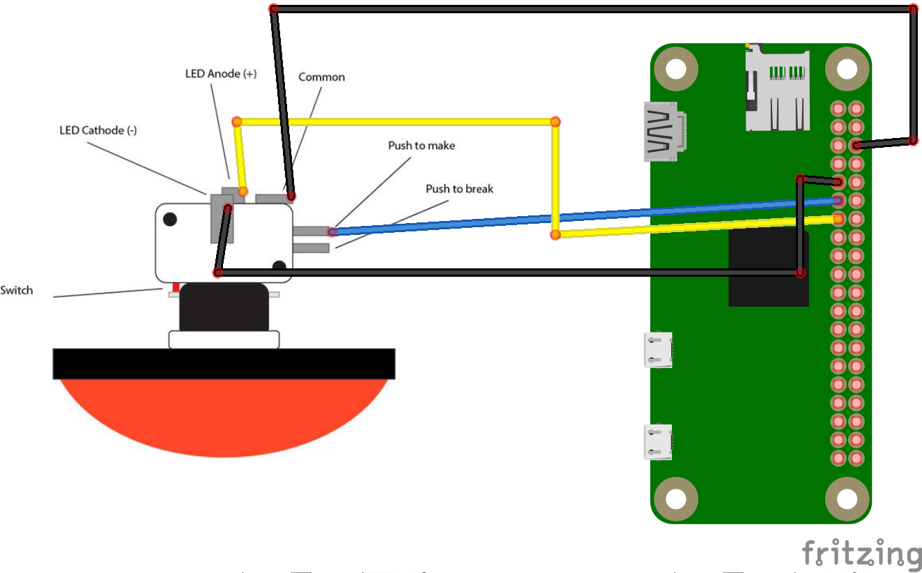
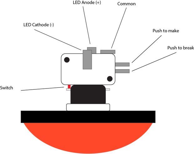
The big dome push button is a big round button - with around 100mm out diameter with a small LED. It says it works at 12V, but the 3.3v of the Raspberry PI is enough to light it up
Use the schematic for testing
The code:
from RPi import GPIO
takeButton = 17
ledButton = 27

GPIO.setmode(GPIO.BCM)
GPIO.setup(takeButton, GPIO.IN, GPIO.PUD_UP)
GPIO.setup(ledButton,GPIO.OUT)

#Light led
GPIO.output(ledButton,True)
# Blocking function
GPIO.wait_for_edge(takeButton,GPIO.FALLING)
print ("Button Pressed")
GPIO.output(ledButton,False)
GPIO.cleanup()
Some explaining of the code
One of the forms of getting values from GPIOS is through interrupts (other is polling) - edge detection.
The edge is the name of the transition from HIGH to LOW (falling edge) or LOW to HIGH (rising edge). When the PIN is not connected to anything, any read will be undefined. A workaround is to have a pull up/down resistor in said PIN. The Raspberry PI allows to configure pull up/down resistors through software.
The line
GPIO.setup(takeButton, GPIO.IN, GPIO.PUD_UP)
configures that PIN to do just that - pull up
Why pull up ? Well, the big dome push button has 2 PINs - push to break or push to make (just like the small push buttons that often come with Arduino/Raspberry PI kits). I've wired it to the "push to make" PIN of the button. When pressed, the circuit closes and electricity passes (normally open).
The line
GPIO.wait_for_edge(takeButton,GPIO.FALLING)
will wait (effectively suspending the execution of the script) until it detects the falling of the PIN - releasing the button will cut the flow of electricity and the PIN will go from 3.3v to 0v
The LED PIN is just to light up the LED on the button
More info on push switches from Arduino Tutorials, Wikipedia on push to make or push to break and GPIO interrupts
Now, let's combine a push button with the camera - Take a picture only when the button is pressed
import picamera<br>from time import sleep
from RPi import GPIO
from PIL import Image

# NOTE: This is what will be the cancel button in the main program
# I'm just using it here for sake of clarity in the video
takeButton = 24
ledCancel = 5

GPIO.setmode(GPIO.BCM)
GPIO.setup(takeButton, GPIO.IN, GPIO.PUD_UP)
GPIO.setup(ledCancel,GPIO.OUT)

def onLeds():
    GPIO.output(ledCancel,True)
    sleep(1)

def offLeds():
    GPIO.output(ledCancel,False)

# Function to overlay image
def overlayCounter():
    #load images
    img1 = Image.open('3.png')
    img2 = Image.open('2.png')
    img3 = Image.open('1.png')
    # Create an overlay
    # Used with img1 because all are the same size
    pad = Image.new('RGB', (
        ((img1.size[0] + 31) // 32) * 32,
        ((img1.size[1] + 15) // 16) * 16,
    ))

    # paste the overlay - 3
    pad.paste(img1, (0,0))
    ov = camera.add_overlay(pad.tobytes(), size=img1.size)
    ov.alpha = 200
    # layer is 3 because camera preview is on layer 2
    ov.layer = 3
    sleep(1)
    camera.remove_overlay(ov)

    # paste the overlay - 2
    pad.paste(img2, (0,0))
    ov = camera.add_overlay(pad.tobytes(), size=img2.size)
    ov.alpha = 200
    # layer is 3 because camera preview is on layer 2
    ov.layer = 3
    sleep(1)

    camera.remove_overlay(ov)

    # paste the overlay - 1
    pad.paste(img3, (0,0))
    ov = camera.add_overlay(pad.tobytes(), size=img3.size)
    ov.alpha = 200
    # layer is 3 because camera preview is on layer 2
    ov.layer = 3
    sleep(1)
    camera.remove_overlay(ov)

camera = picamera.PiCamera()
camera.resolution = (1280,1024)
camera.framerate = 24
camera.start_preview()
GPIO.wait_for_edge(takeButton,GPIO.FALLING)
onLeds()
overlayCounter()
camera.capture('pushTesting.jpg')
camera.stop_preview()
offLeds()
GPIO.cleanup()
A bit of code explanation
It starts the camera preview and waits there until a button is pressed. After the button is pressed, the LED lights up and the countdown starts. When reaching the end, the picture is taken and the LED is turned off
Post to Twitter
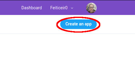
Now, we're going to use Python and tweet a tweet ! :) You'll need a image to post - choose wisely .
First, we need to acess twitter API and for that we need to create an APP . Go to https://apps.twitter.com a create a new application.
You'll need to apply for a developer account - fill in some questions and confirm your email address. After that, you'll be able to create a new APP .
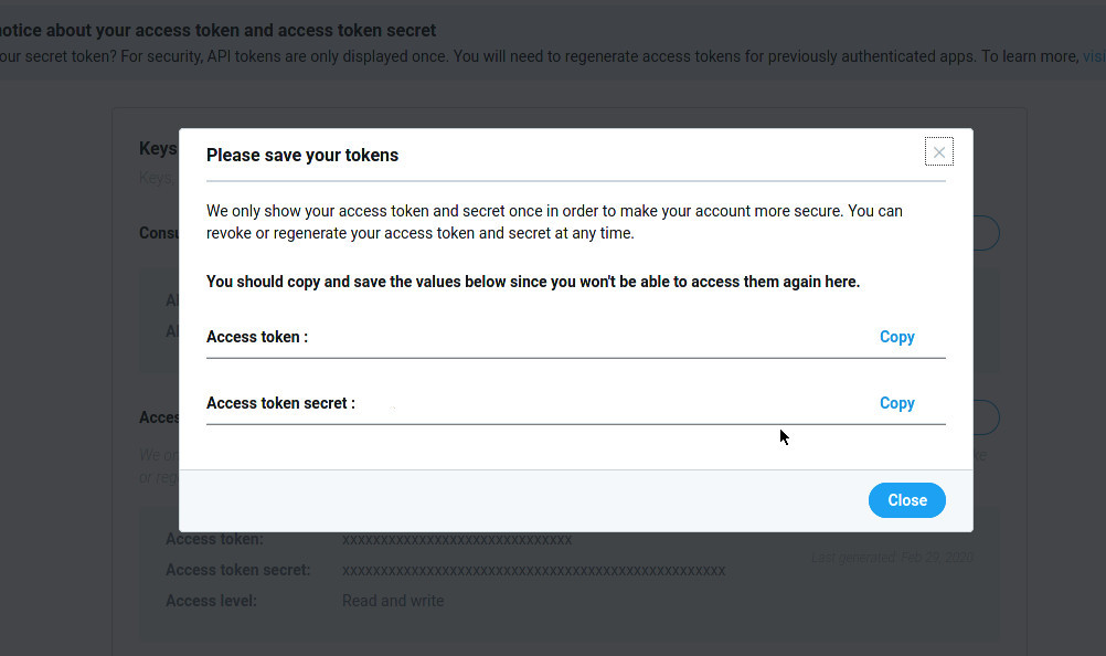
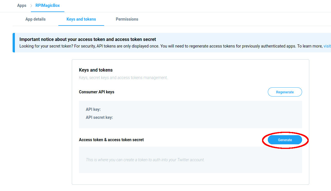
After creating the APP, navigate to Keys and Tokens and Generate an Access Token and Access Token Secret. A window will be shown with the Keys ONLY ONCE - COPY THOSE AND SAVE THEM FOR LATER .
Use the following code to send a picture to your twitter account. Don't forget to fill in:
- consumer_key
- consumer_secret
- access_token
- access_token_secret
twitter message is the text to send in the tweet .
jpg_foto_to_send is a picture that will be attached to the tweet. Please have some picture in the same directory as the Python script and change the name in the code.
import tweepy<br>
# Twitter settings
def get_api(cfg):
    auth = tweepy.OAuthHandler(cfg['consumer_key'], cfg['consumer_secret'])
    auth.set_access_token(cfg['access_token'], cfg['access_token_secret'])
    return tweepy.API(auth)

# Send to twitter
def sendToTwitter():
    cfg = {
        "consumer_key"      : "",
        "consumer_secret"   : "",
        "access_token"      : "",
        "access_token_secret"   : ""
                                                                }

    api = get_api(cfg)
    # Status Message
    tweet = "Twitter message"
    status = api.update_with_media("jpg_foto_to_Send",tweet)

sendToTwitter()
Check your Twitter feed for your tweet .
Or bellow:
#RaspberryPI MagicBox. Take pictures, review them and choose to send them to twitter and Facebook. Powered by Raspberry PI. @@Raspberry_Pi #RaspberryPI #RaspberryPIProject pic.twitter.com/cCL33Zjb8p
— Bruno Ricardo Santos (@feiticeir0) February 29, 2020
Combining Some Elements


Let's now combine the Big Dome Push button, pressing it, counting down, take a picture, decide whether or not to send it to twitter.
We will add another overlay image and use all the three push buttons . When the picture is taken, all the 3 buttons LEDs will light up.
We add another picture, that shows the icons to post to social networks
SelectOption.png shows the icons of Facebook and Twitter
Aenviar.png is just a message saying that is sending to the Social Networks.
In the video is not shown the Blue push button (front of the camera), but the LED is on and it starts to blink as soon as it is pressed.
The code is attached if you prefer
This is the final testing code before the main program .
# coding=utf-8

import picamera
import _thread
import subprocess as sp
from time import sleep
from RPi import GPIO
from PIL import Image

import threading

# Twitter
import tweepy

# Facebook
import facebook

# Button to take picture
takeButton = 17
# SocialNetwork Button
socialNetworkButton = 23

# Cancel Picture
cancelButton = 24

# Take picture button LED
takePicButtonLed =  27
# Post to Social Network button LED
postSNLed = 22
# Cancel button LED
cancelButtonLed = 5

GPIO.setmode(GPIO.BCM)
GPIO.setup(takeButton, GPIO.IN, GPIO.PUD_UP)
GPIO.setup(socialNetworkButton, GPIO.IN, GPIO.PUD_UP)
GPIO.setup(cancelButton, GPIO.IN, GPIO.PUD_UP)

GPIO.setup(takePicButtonLed,GPIO.OUT)
GPIO.setup(postSNLed,GPIO.OUT)
GPIO.setup(cancelButtonLed,GPIO.OUT)

# Twitter settings
def get_api(cfg):
    auth = tweepy.OAuthHandler(cfg['consumer_key'], cfg['consumer_secret'])
    auth.set_access_token(cfg['access_token'], cfg['access_token_secret'])
    return tweepy.API(auth)

# Send to twitter
def sendToTwitter():
    cfg = {
        "consumer_key"        : "",
        "consumer_secret"    : "",
        "access_token"        : "",
        "access_token_secret"    : ""
    }

    api = get_api(cfg)
    # Status Message
    tweet = "MagicBox instructable testing. #MagicBox #RaspberryPI #Raspberry #Instructables"
    status = api.update_with_media("pushTesting.jpg",tweet)

# Facebook AOth
def get_api_facebook(cfg):
    graph = facebook.GraphAPI(cfg['access_token'])
    # Get page token to post as the page. You can skip
    # the following if you want to post as yourself.
    resp = graph.get_object('me/accounts')
    page_access_token = None
    for page in resp['data']:
        if page['id'] == cfg['page_id']:
            page_access_token = page['access_token']

    graph = facebook.GraphAPI(page_access_token)
    return graph

# Send to facebook
def sendToFacebook():
    #Values for access
    cfg = {
        "page_id"    : "",
        "access_token"    : ""
    }

    api = get_api_facebook(cfg)
    caption = "Caption the image"
    albumid = ""
    api.put_photo(image=open("pushTesting.jpg","rb"),caption="Caption the image")

# Light only TakePicButtonLed
def onlyTakePicLed():
    GPIO.output(takePicButtonLed,True)
    GPIO.output(postSNLed,False)
    GPIO.output(cancelButtonLed,False)

# Light only Cancel and SocialNetwork button
def cancelPostLEDS():
    GPIO.output(takePicButtonLed,False)
    GPIO.output(postSNLed,True)
    GPIO.output(cancelButtonLed,True)

# Blink take picture LED while count down
def countingTimerPicture():
    GPIO.output(takePicButtonLed,True)
    sleep(0.5)
    GPIO.output(takePicButtonLed,False)
    sleep(0.5)
    GPIO.output(takePicButtonLed,True)
    sleep(0.5)
    GPIO.output(takePicButtonLed,False)
    sleep(0.5)
    GPIO.output(takePicButtonLed,True)
    sleep(0.5)
    GPIO.output(takePicButtonLed,False)


# Blink postSNLed while posting to social networks
def blinkPosting(stop_event):
    # Start
    while (not stop_event.is_set()):
        print ("off")
        GPIO.output(postSNLed,False)
        sleep(0.5)
        print ("on")
        GPIO.output(postSNLed,True)
        sleep(0.5)


def timer():
    GPIO.output(takePicButtonLed,True)
    sleep(1)
    GPIO.output(postSNLed,True)
    sleep(1)
    GPIO.output(cancelButtonLed,True)
    sleep(1)

def showAllLeds():
    GPIO.output(takePicButtonLed,True)
    GPIO.output(postSNLed,True)
    GPIO.output(cancelButtonLed,True)

# Display a preview on layer 1
def displayPreview(imgName):
    # Since the PIL image show is a crap
    # we use the overlay from the camera to display
    # the preview

    img = Image.open(imgName)
    padding = Image.new('RGB', (
        ((img.size[0] + 31) // 32) * 32,
        ((img.size[1] + 15) // 16) * 16,
    ))
    padding.paste(img, (0,0))
    ov = camera.add_overlay(padding.tobytes(), size=img.size)
    ov.layer = 1

# Display a preview on layer 3
def displayPreview3(imgName):
    # Since the PIL image show is a crapp
    # we use the overlay from the camera to display
    # the preview

    img = Image.open(imgName)
    padding = Image.new('RGB', (
        ((img.size[0] + 31) // 32) * 32,
        ((img.size[1] + 15) // 16) * 16,
    ))
    padding.paste(img, (0,0))
    ov = camera.add_overlay(padding.tobytes(), size=img.size)
    ov.alpha = 150
    ov.layer = 3
    return ov

# Function overlaySocialNetwork
def overlaysn():
    imgsn = Image.open('SelectOption.png')
    # Create Overlay
    pad = Image.new('RGB',(
        ((imgsn.size[0] + 31) // 32) * 32,
                ((imgsn.size[1] + 15) // 16) * 16,
        ))

    # Paste the overlay
    pad.paste(imgsn, (0,0))
    ov = camera.add_overlay(pad.tobytes(), size=imgsn.size)
    ov.alpha = 100
    ov.layer = 3
    return ov

# Function to overlay image
def overlayCounter():
    #load images
    img1 = Image.open('3.png')
    img2 = Image.open('2.png')
    img3 = Image.open('1.png')
    # Create an overlay
    # Used with img1 because all are the same size
    pad = Image.new('RGB', (
        ((img1.size[0] + 31) // 32) * 32,
        ((img1.size[1] + 15) // 16) * 16,
    ))

    # paste the overlay - 3
    pad.paste(img1, (0,0))
    ov = camera.add_overlay(pad.tobytes(), size=img1.size)
    ov.alpha = 200
    # layer is 3 because camera preview is on layer 2
    ov.layer = 3
    sleep(1)
    camera.remove_overlay(ov)

    # paste the overlay - 2
    pad.paste(img2, (0,0))
    ov = camera.add_overlay(pad.tobytes(), size=img2.size)
    ov.alpha = 200
    # layer is 3 because camera preview is on layer 2
    ov.layer = 3
    sleep(1)

    camera.remove_overlay(ov)

    # paste the overlay - 1
    pad.paste(img3, (0,0))
    ov = camera.add_overlay(pad.tobytes(), size=img3.size)
    ov.alpha = 200
    # layer is 3 because camera preview is on layer 2
    ov.layer = 3
    sleep(1)
    camera.remove_overlay(ov)

# Main function
# Clear screen so that the boot messages are not present
# probably it could be better be doing this in bash
tmp = sp.call('clear',shell=True)
camera = picamera.PiCamera()
camera.resolution = (1280,1024)
camera.framerate = 24
camera.brightness = 55
camera.sharpness = 0
camera.contrast = 0
#camera.exposure_compensation = 0
#camera.exposure_mode = 'auto'
#camera.meter_mode = 'average'
# Testing here
try:
    while (True):
        camera.start_preview()
    #Show LED Only for Take Picture
        onlyTakePicLed()
    # Wait for button to take Picture
        GPIO.wait_for_edge(takeButton,GPIO.FALLING)

        # Start a thread to count with the LEDs while the images are shown
        # Probably could be used in the overlayCounter function,
        # because it also has timers to show the pictures, but the led effects would not
        # be the same
        _thread.start_new_thread ( countingTimerPicture,() )

        # Show the pictures overlay in the camera picture
        overlayCounter()
        # Show all LEDS while taking the picture
        showAllLeds()
        camera.capture('pushTesting.jpg')
        camera.stop_preview()

        #display image
        displayPreview('pushTesting.jpg')

        # Show overlay
        oo = overlaysn()
        # Show LEDs to Cancel or Post to Social Networks
        cancelPostLEDS()
        GPIO.add_event_detect(socialNetworkButton,GPIO.FALLING)
        GPIO.add_event_detect(cancelButton,GPIO.FALLING)
        while (True):
            if GPIO.event_detected(socialNetworkButton):
                camera.remove_overlay(oo)
                GPIO.output(cancelButtonLed,False)
                o = displayPreview3('Aenviar.png')
        	#print "Social Networks Button"
                sendToTwitter()
                sendToFacebook()
                camera.remove_overlay(o)
                break
            if GPIO.event_detected(cancelButton):
                #print "Canceled"
                camera.remove_overlay(oo)
                break

	# reset GPIOS
        GPIO.remove_event_detect(socialNetworkButton)
        GPIO.remove_event_detect(cancelButton)
        GPIO.remove_event_detect(takeButton)
        camera.stop_preview()

except KeyboardInterrupt:
    print ("Exited...")
    #offLeds()
    GPIO.cleanup()
Wiring
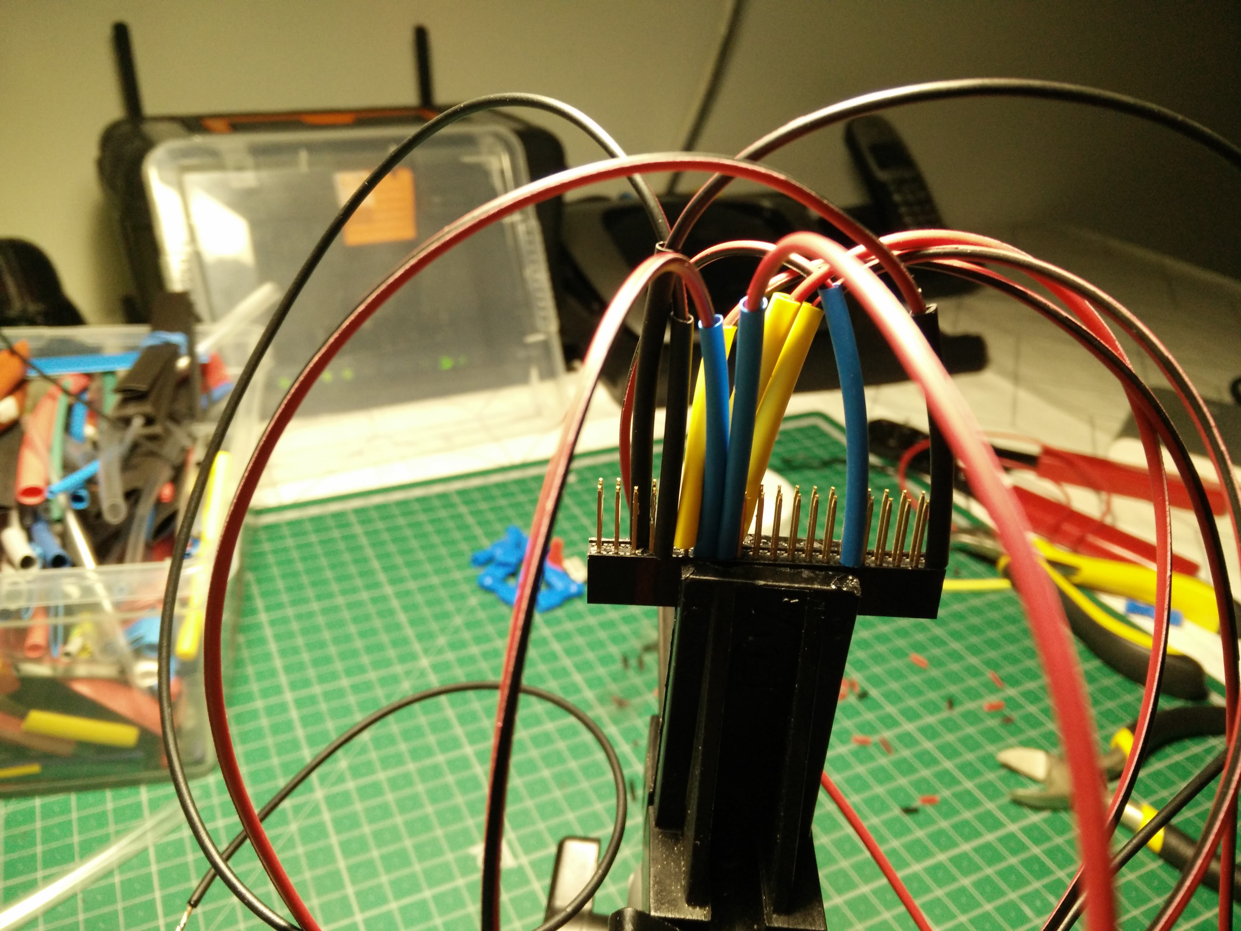
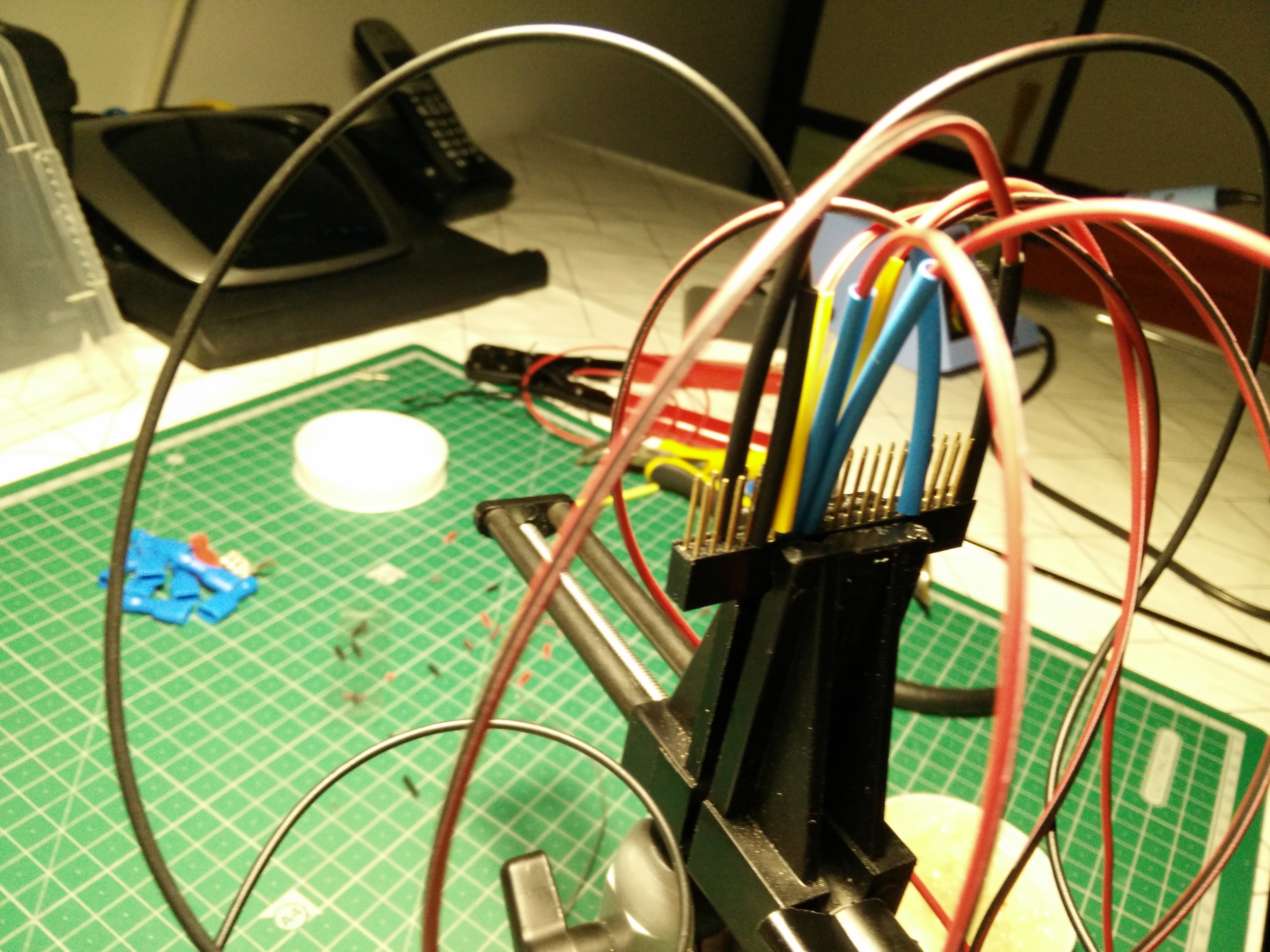
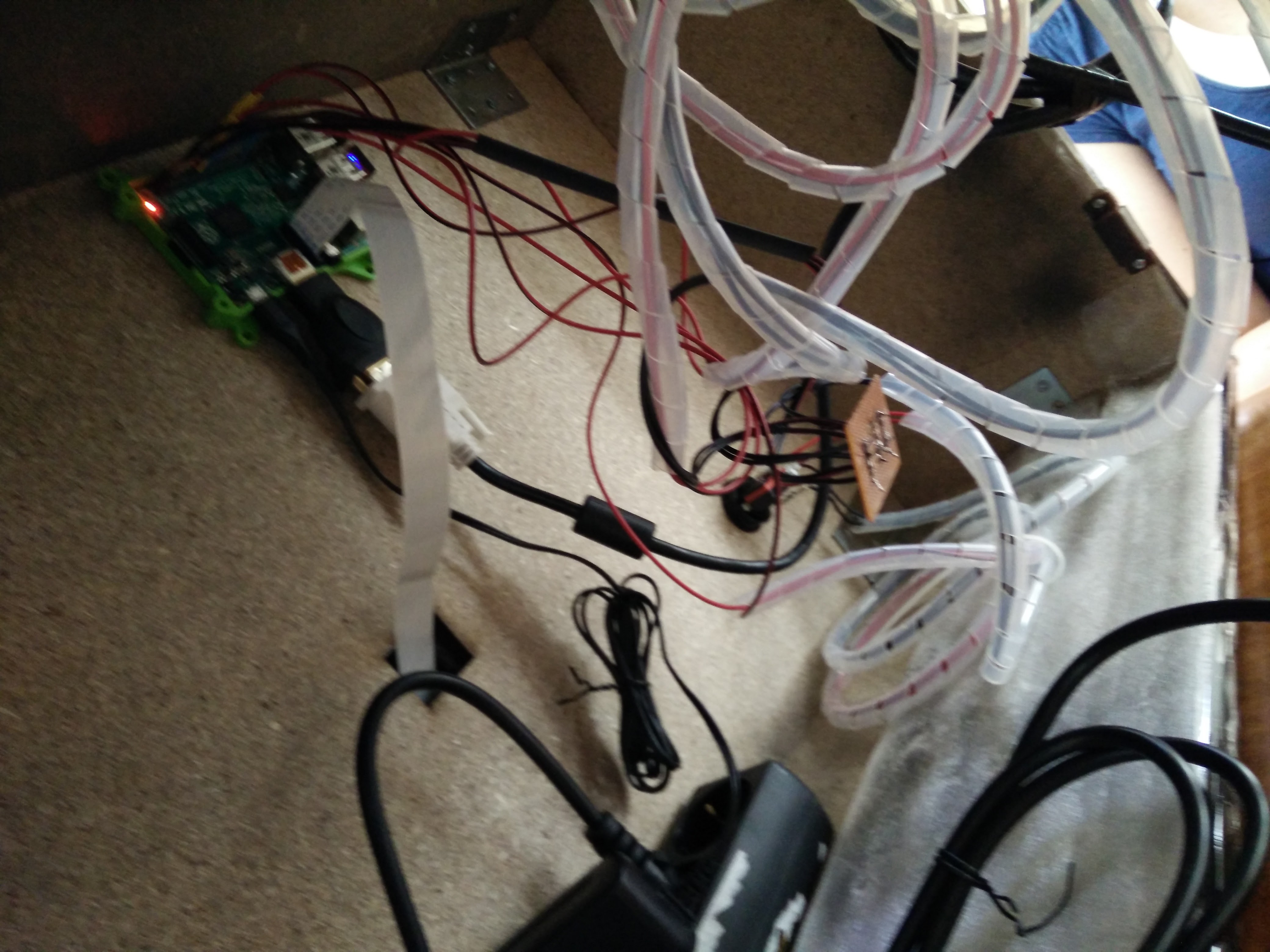
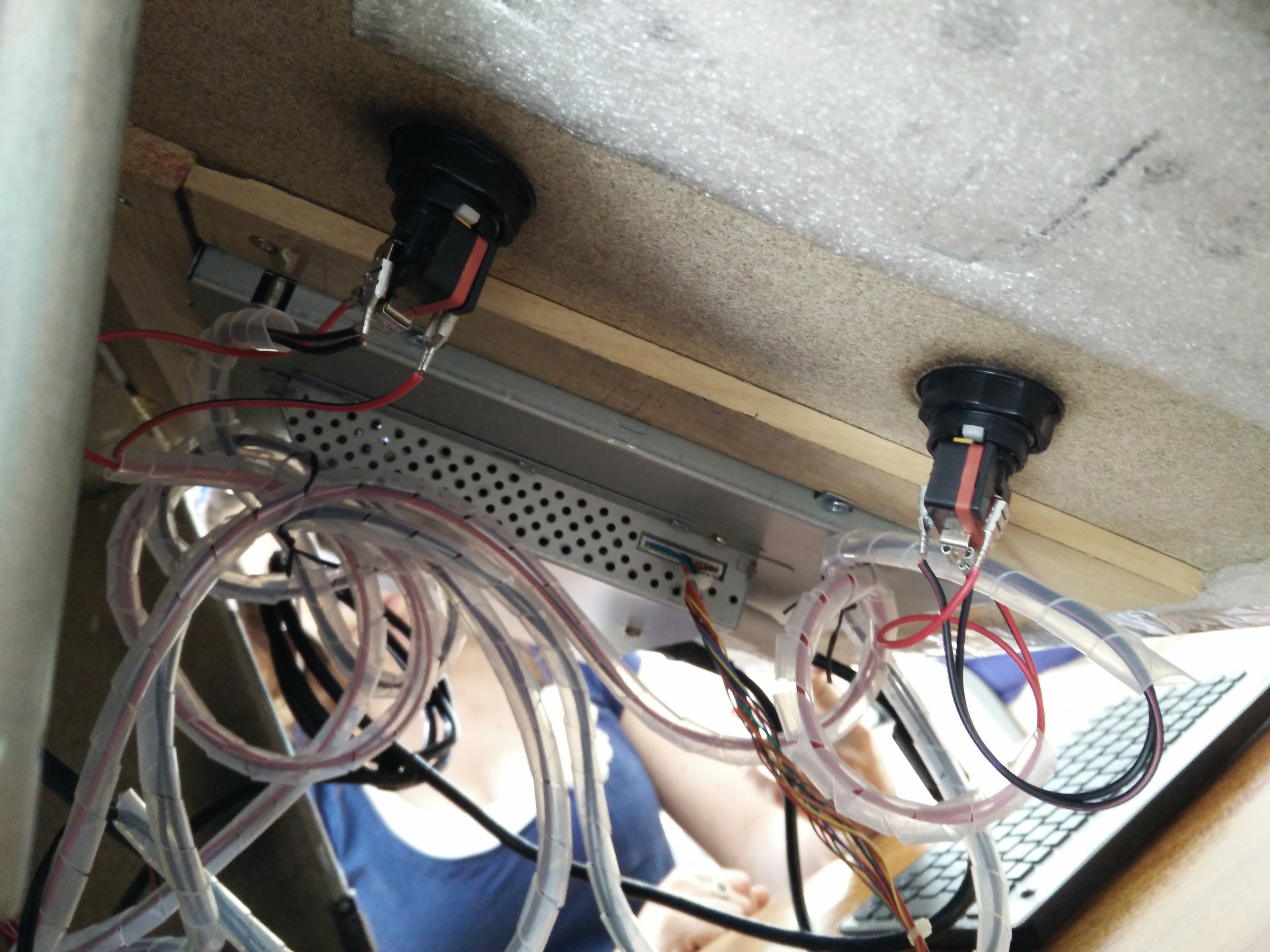
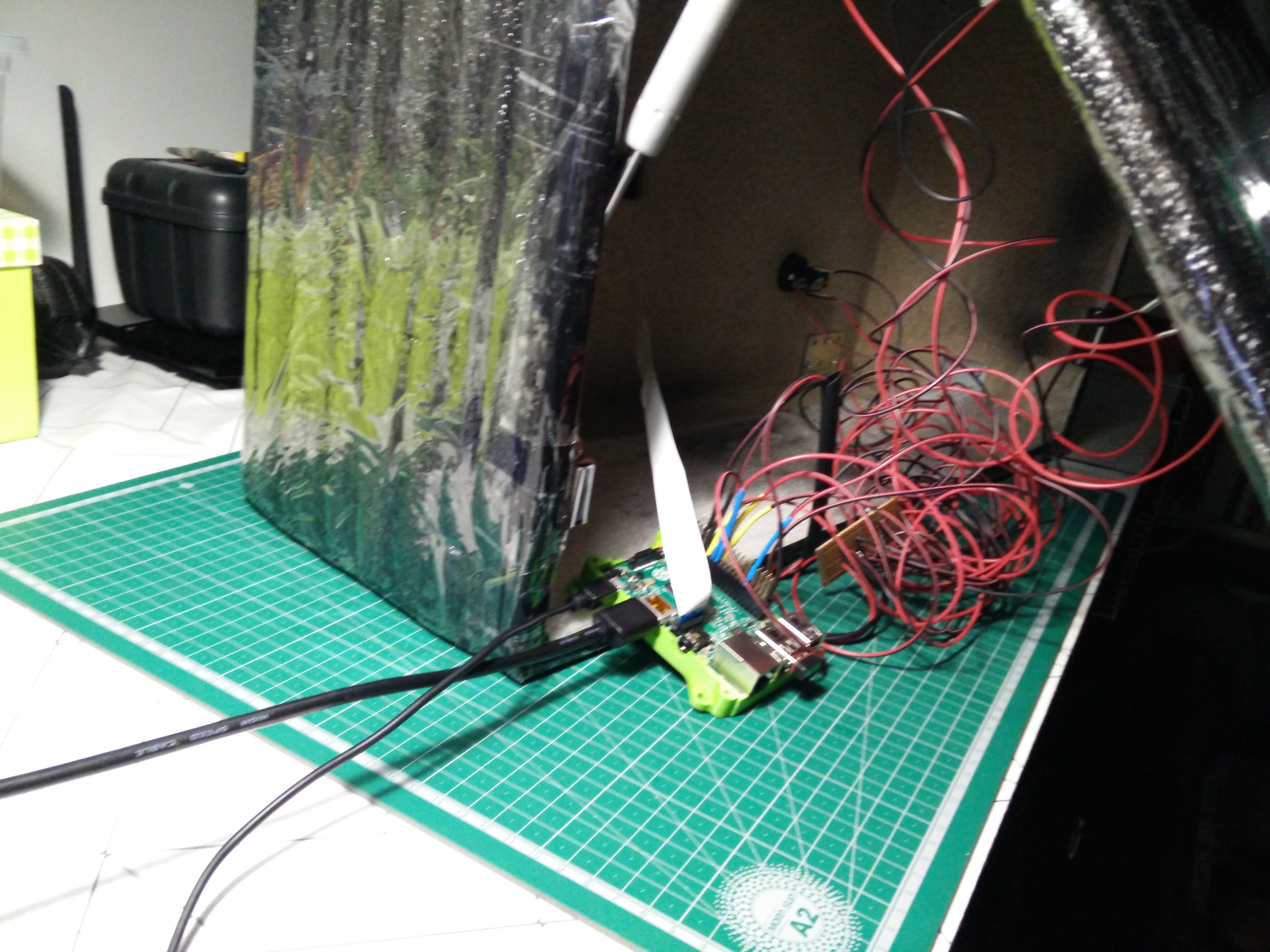
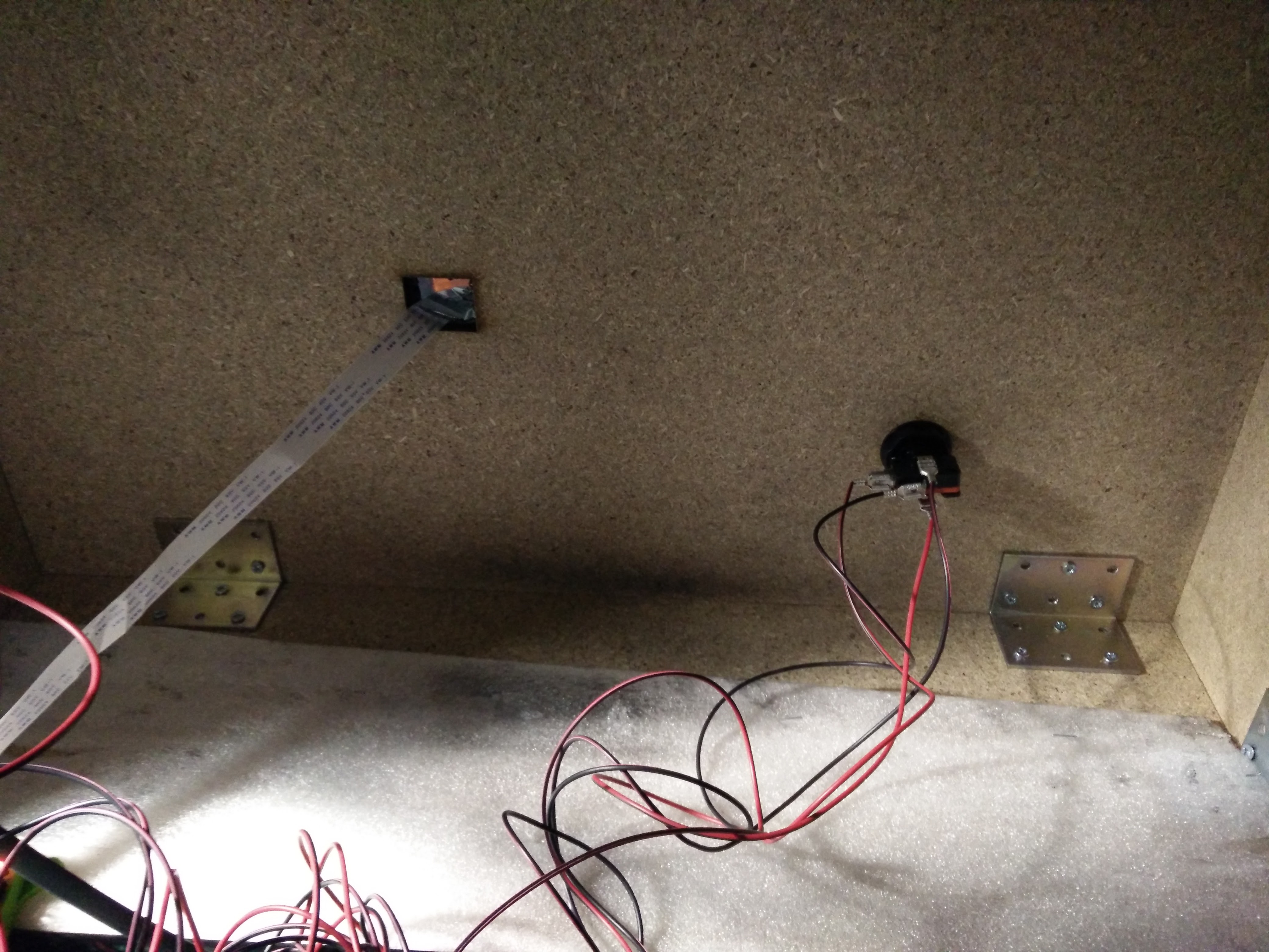
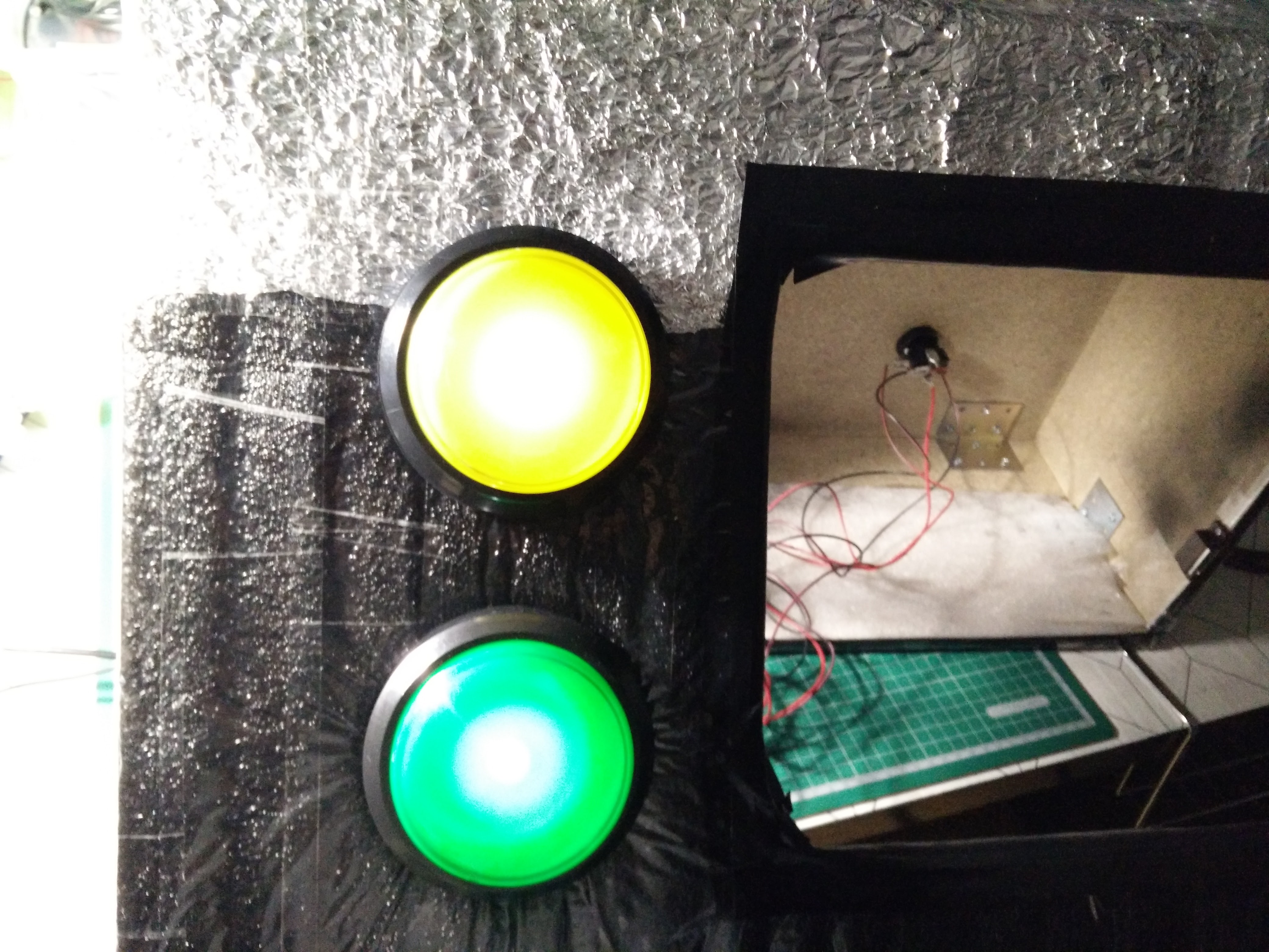
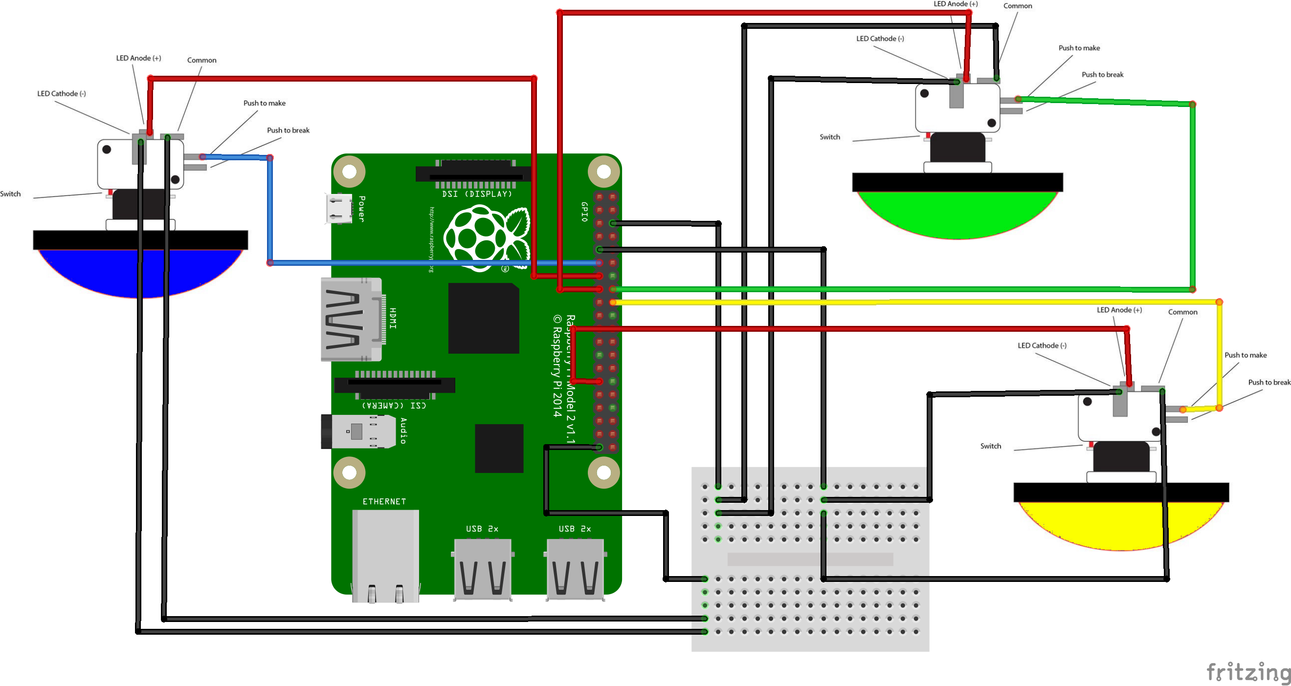
The wiring is just wiring the Big Dome Push buttons to the Raspberry PI.
Just follow the Fritzing Schematic.
The connections are:
ConnectionRPI GPIO PIN GND Green Push ButtonGND (#3) GND Yellow Push ButtonGND (#9) GND Blue Push ButtonGND(#39) Take Picture(Blue Push Button "Push to make")17 (BCM) Post to Social Networks (Green Push Button "Push to make")23 (BCM) Cancel (Yellow Push Button "Push to make")24 (BCM) Blue Push button LED27 (BCM) Green Push button LED22 (BCM) Yellow Push button LED5 (BCM)The heat shrink also is color coded
- Black is GND connections
- Yellow are "push to make" connections
- Blue are LED connections
GPIO.BCM numbers vs GPIO.BOARD connections
Since my connections are BCM, I think now is a good time to talk about it and the difference between BCM and BOARD.
The main difference is how do you refer to the GPIO PINs, which in turn will drive how you do the connections. GPIO.board will refer the PINs by the number printed on any GPIO layout on the internet.
GPIO.BCM referes to the PIN numbers as the Broadcom SOC sees them. This is likely to change along newer versions of the Raspberry PI.
On the pinout.xyz site, the board numbers are the ones right next to the pins and the BCM are refered like that - BCM X (where X is the number)
The MagicBox

The attached code to this step is the final.
You can run it at raspberry PI boot, without even needing to login. To do that, just create this small script in the directory you have placed the code - change paths accordingly
#!/bin/bash
cd /home/pi/magicbox
python MagicBox.py
Make it executable
chmod +x start_magicbox.sh
Now, call it in /etc/rc.local, just before the exit 0 instuction
sudo vi /etc/rc.local
/home/pi/magicbox/start_magicbox.sh &
save and quit.
Now, with every reboot, the Python program will execute
NOTE: All the image files must be in the same directory as the script. You need to have:
- 1.png
- 2.png
- 3.png
- Aenviar.png
- SelectOption.png
You can get all these files at MagicBox's github.