Raspberry Pi Spotify Player With 3D Printed Case
by holmestobias in Circuits > Audio
10113 Views, 93 Favorites, 0 Comments
Raspberry Pi Spotify Player With 3D Printed Case
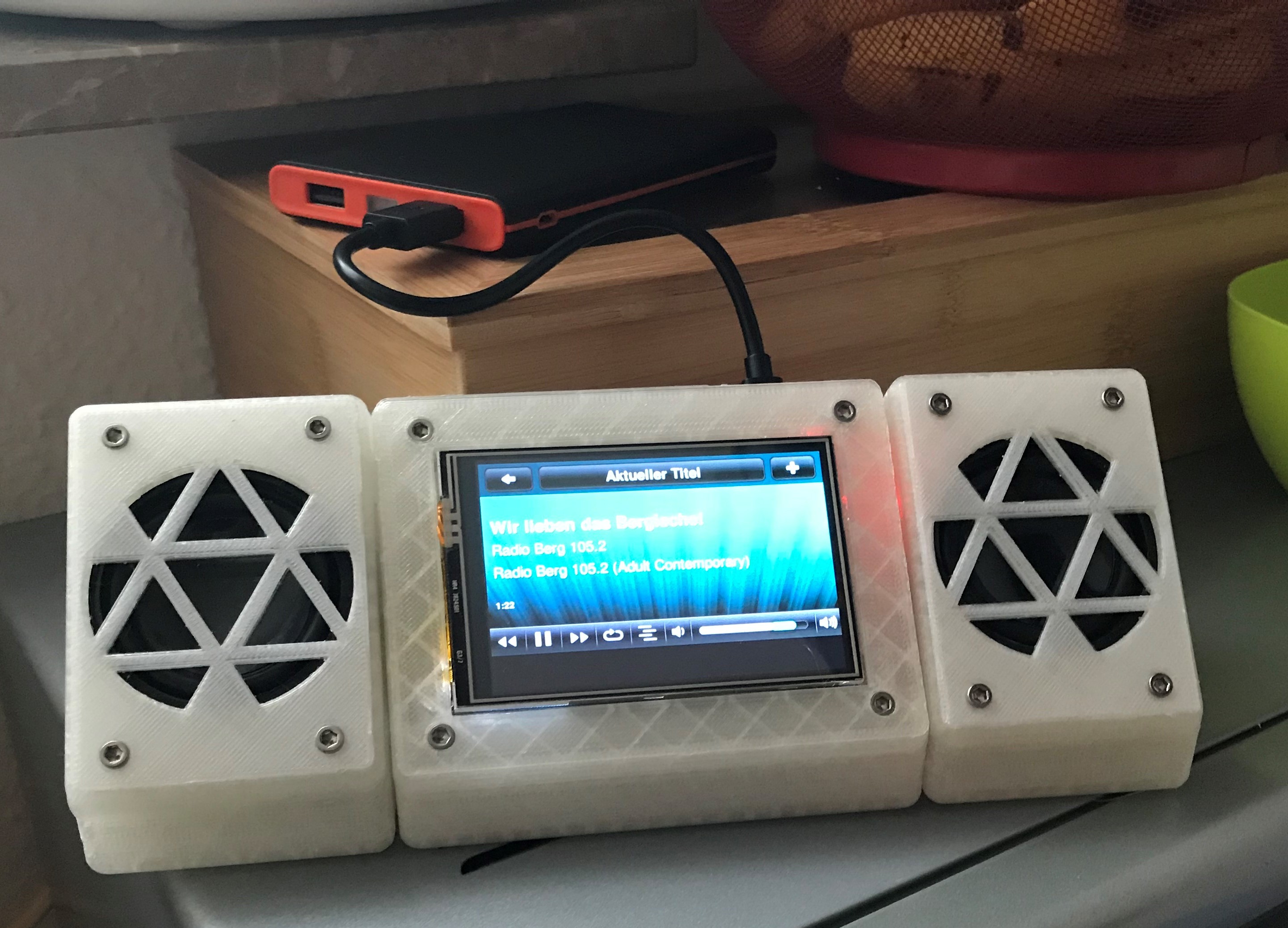
In this instructable I am going to show you how to make a Raspberry Pi based Music Player that can play local music, web radio stations and acts as a spotify connect speaker, all housed in a wall mountable 3D printed case.
I built this music player for my girlfriends kitchen, as we like to listen to music while cooking or baking, but the computer speakers blaring from the livingroom just don't cut it.
You will need:
- Raspberry Pi 3
- Micro SD Card (min. 8GB)
- Stereo speakers with an integraded USB DAC
- Safe Shutdown Circuit
- 3.5" Touchscreen
- Female to Male Micro USB Cable
- Soldering Iron
- Wire Stripper
- Wires
For setup:
- Keyboard
- Mouse
- HDMI Monitor
Setting Up the Pi
First let's sort out the software side of things. The music player is based on Logitechs popular, but retired line of Squeezebox players. The Pi runs the LogitechMediaServer and the Squeezelite client as well as the Jivvelite interface. You will need basic SSH and comand line skills for the following steps. If you are unfamiliar with SSH, then OverTheWire is a great place to learn how to use the comand line and SSH.
Download Raspbian and flash it to the SD card using one of the following programs:
- Win32DiskImager (Windows)
- ApplePi Baker (Mac)
- Etcher (Mac and Windows)
Insert the SD card into the Pi and connect all peripherals (keyboard, mouse, monitor) and power. Once booted into the desktop environment, set up wifi and enable SSH and GPIO functionality in settings.
You can now disconnect all peripherals and continue via SSH from any computer in the same network to set up the Pi.
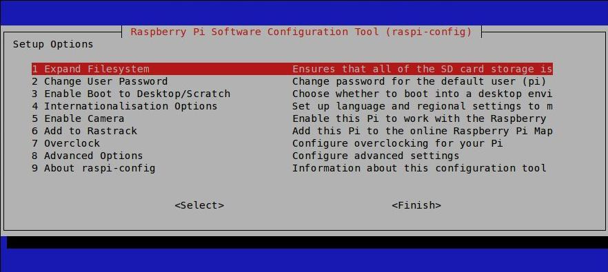
Once connected via SSH, use the following command to access the Raspberry Pi's settigns
sudo raspi-config
Change language, keyboard layout and user password according to your needs (optional), then expand the file system and confirm the reboot prompt.
Next, connect the touchscreen and install any drivers that are needed (depends on which screen is available to you):
- Adafruit TFT Drivers
- Waveshare TFT Drivers
Once correctly set up, you should see the desktop environment on the touchscreen.
To set up the music player, I followed John Hagensieker's guide to set up the LogitechMediaServer, Squeezelite and Jivelite. Just make sure that the USB speaker is connected and the correct soundcard is selected.
Spotify Connect support can easily be added through the plugin manager in the Logitech Media Server.
I also removed the cursor permanently, for cosmetic reasons, using:
sudo nano /etc/lightdm/lightdm.conf
and changing the following line
#xserver-command = X
into
xserver-command= X -nocursor
The screen can be calibrated using the xinput calibrator as described in the waveshare wiki.
After installing the switch script from mausberry circuits I changed the in- and output to GPIO20 and GPIO21 since the default outputs we're already used by the touchscreen header.
Printing the Case
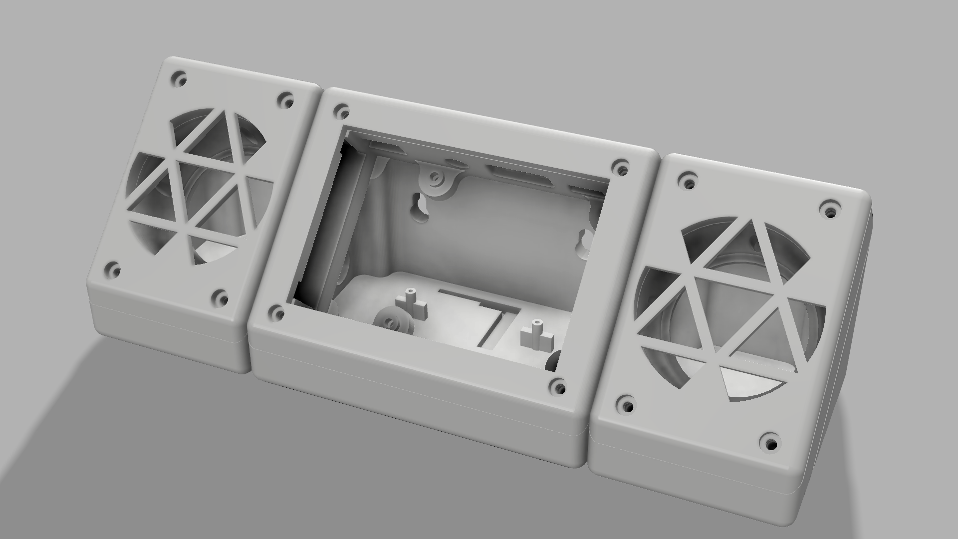
The case is a remix/extension of arcmatt's "Pi TFT plus Console Case" on Thingiverse. In Fusion 360 I added two speaker housings in the same design as the orginal case and modified the main body to feature two wall mounting holes and mounting points for the USB Speakers soundcard and safe shutdown board.
- If you want to modify the case to fit other components, download the *.f3d file.
- If you only want to print the ready made STL files, download the zip file.
The STL files of the middle parts of the main body and speaker housing contain voids for M3 nuts. Pause the print at the corresponding hight and add the nuts before resuming the print.
10% infill should be sufficient for the back and front parts. The middle parts which contain the nuts should be printed at a higher infill level to assure sufficient structural support of the nut voids. Two of the nuts broke free in one of my prints at 10%, leaving no thread to properly hold the bolts.
Here is the link to the thingiverse page for the enclosure
Electronics
_LI.jpg)
For this next step you should have basic soldering skills.
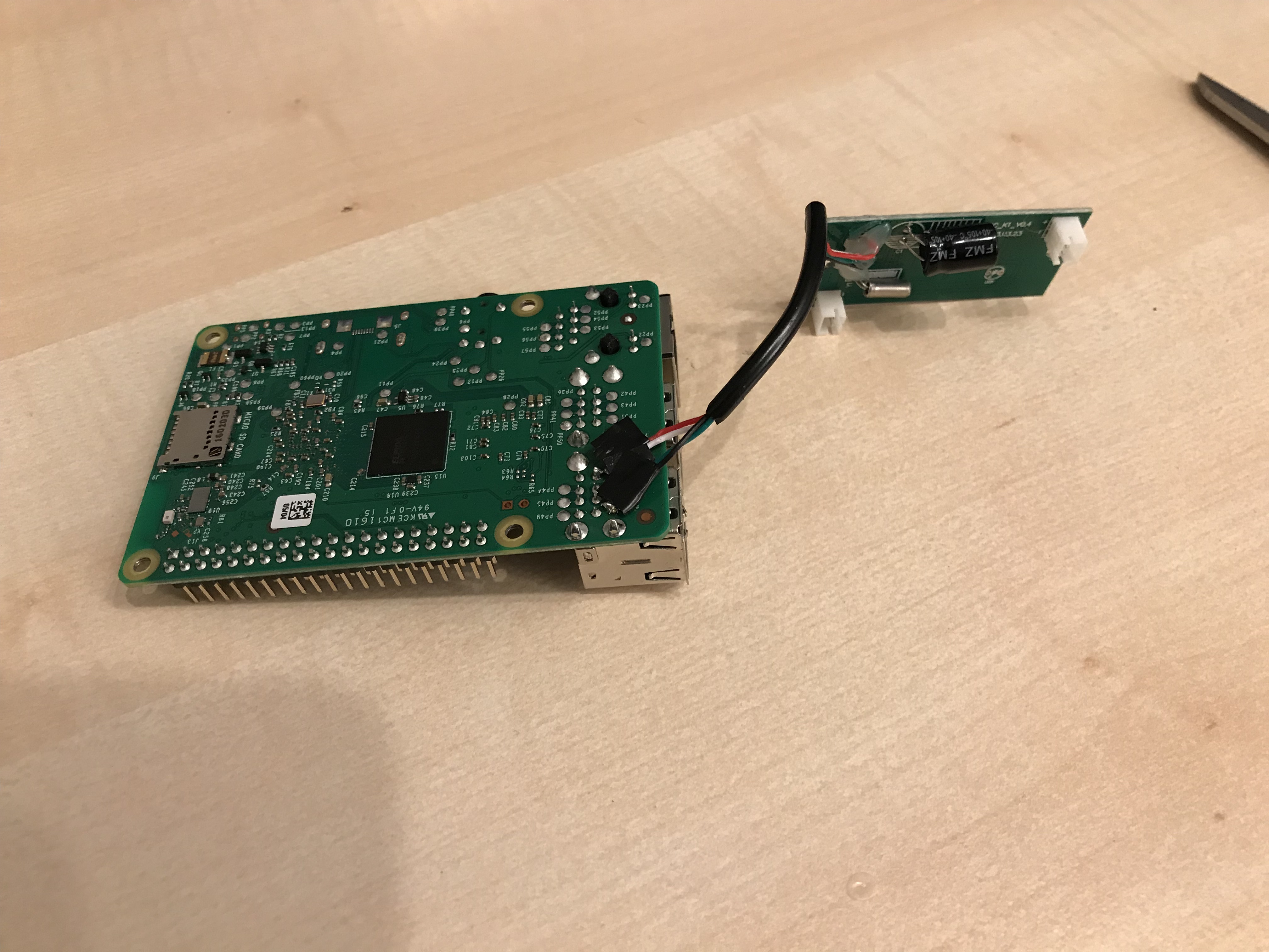
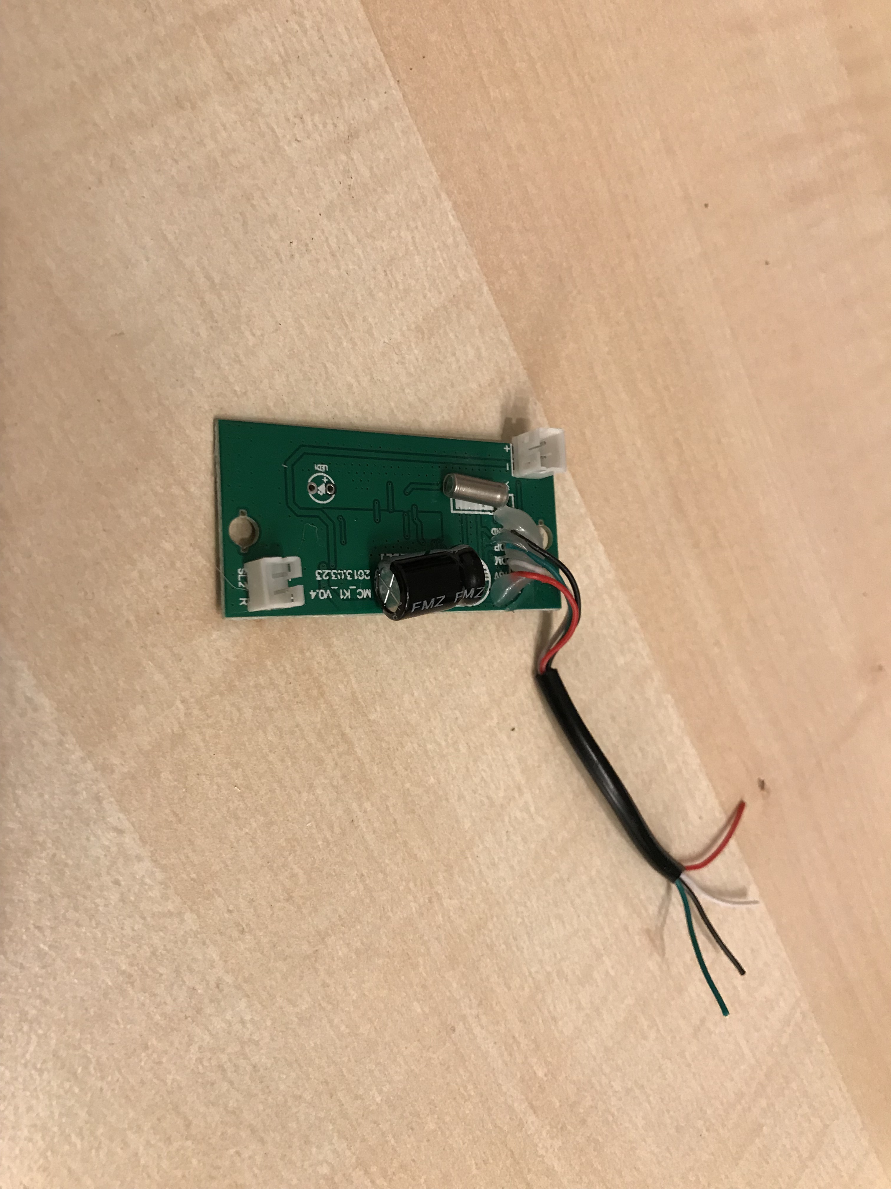
Open the USB speaker and disconnect the speakers from the sound board at their JST cables. Cut and strip the USB cable at an appropriate length from the sound board. To save space I soldered the USB leads directly to the test pads on the underside of the Pi. If you cant trace the pads with a multimeter, here is a good list of pad numbers. I used PP46 through PP48 and the 5V supply pin to connect the sound board (see picture).
Prepare the safe shutdown circuit by desoldering the rocker switch and replacing it with two lengths of insulated wire. Place the switch into the recess and solder the free leads in place.
Cut the male end of the micro USB cable and strip the power and data leads. Solder the red power lead of the USB cable to PP2 and the black lead to PP5 (see picture). The female end of the micro USB cable needs to be connected to the male end of the safe shutdown circuit board. The board can be glued in place at the bottom of the case.
I later added hot glue to all of the solder spots to stabilise and add some tension relief.
Credit for the Pi picture: Wikipedia, user: Multicherry
https://commons.wikimedia.org/wiki/File:Raspberry_Pi_2_Model_B_v1.1_underside_new_(bg_cut_out).jpg
Final Assembly
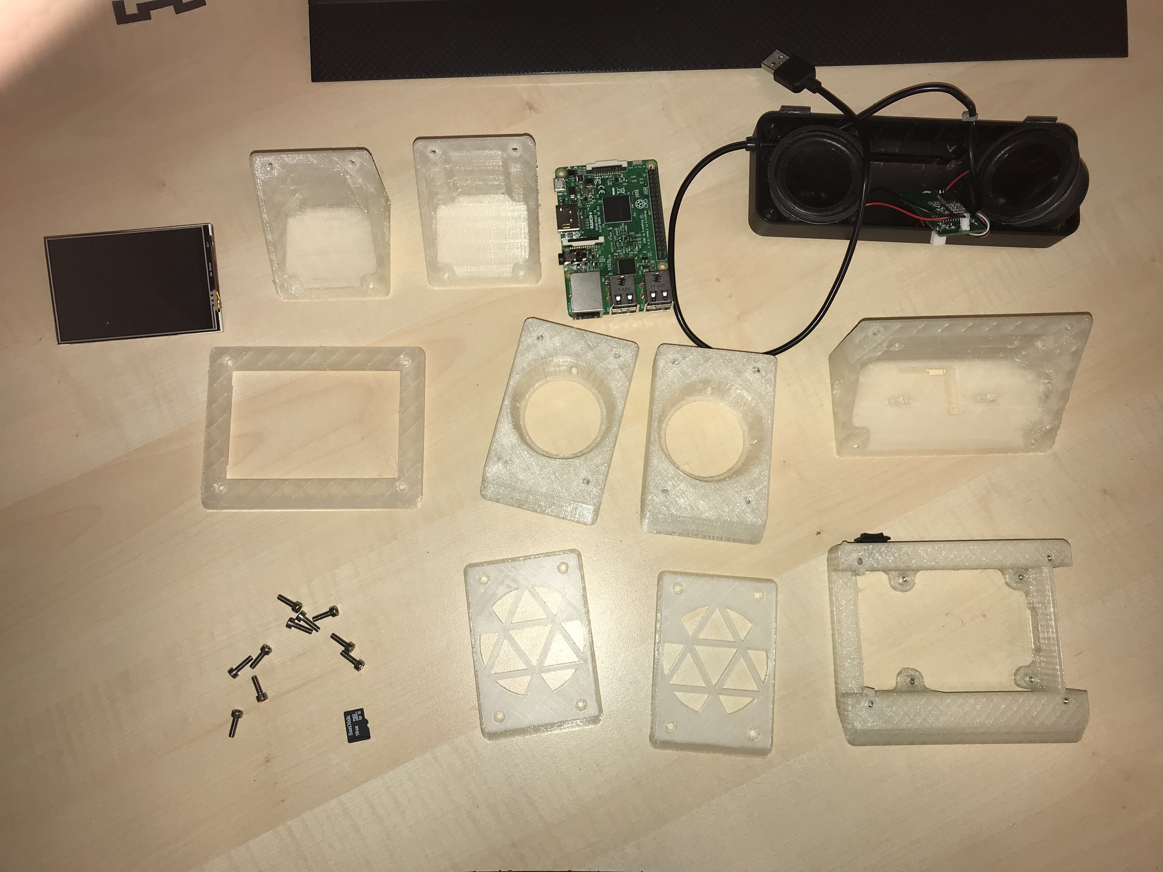
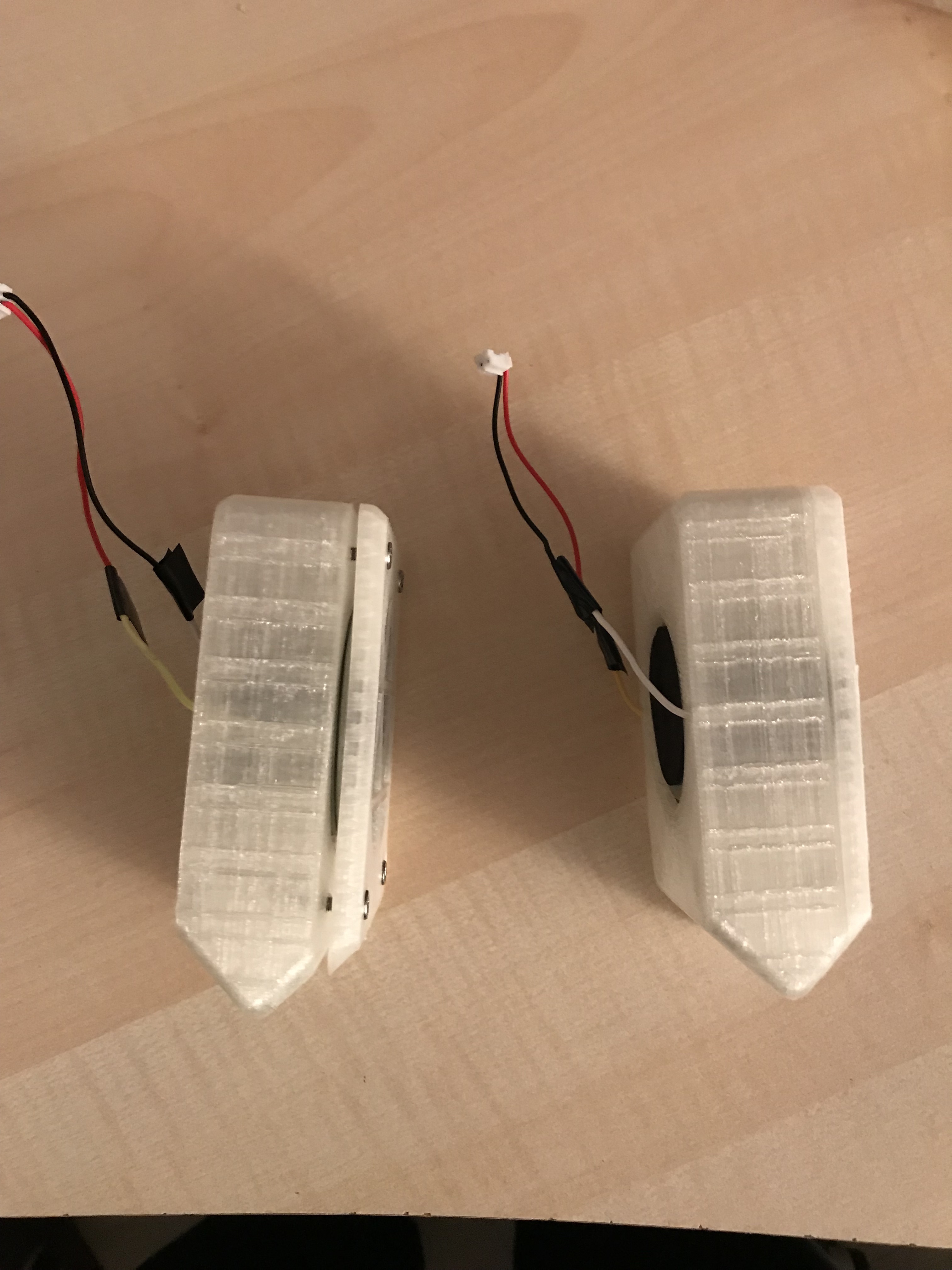
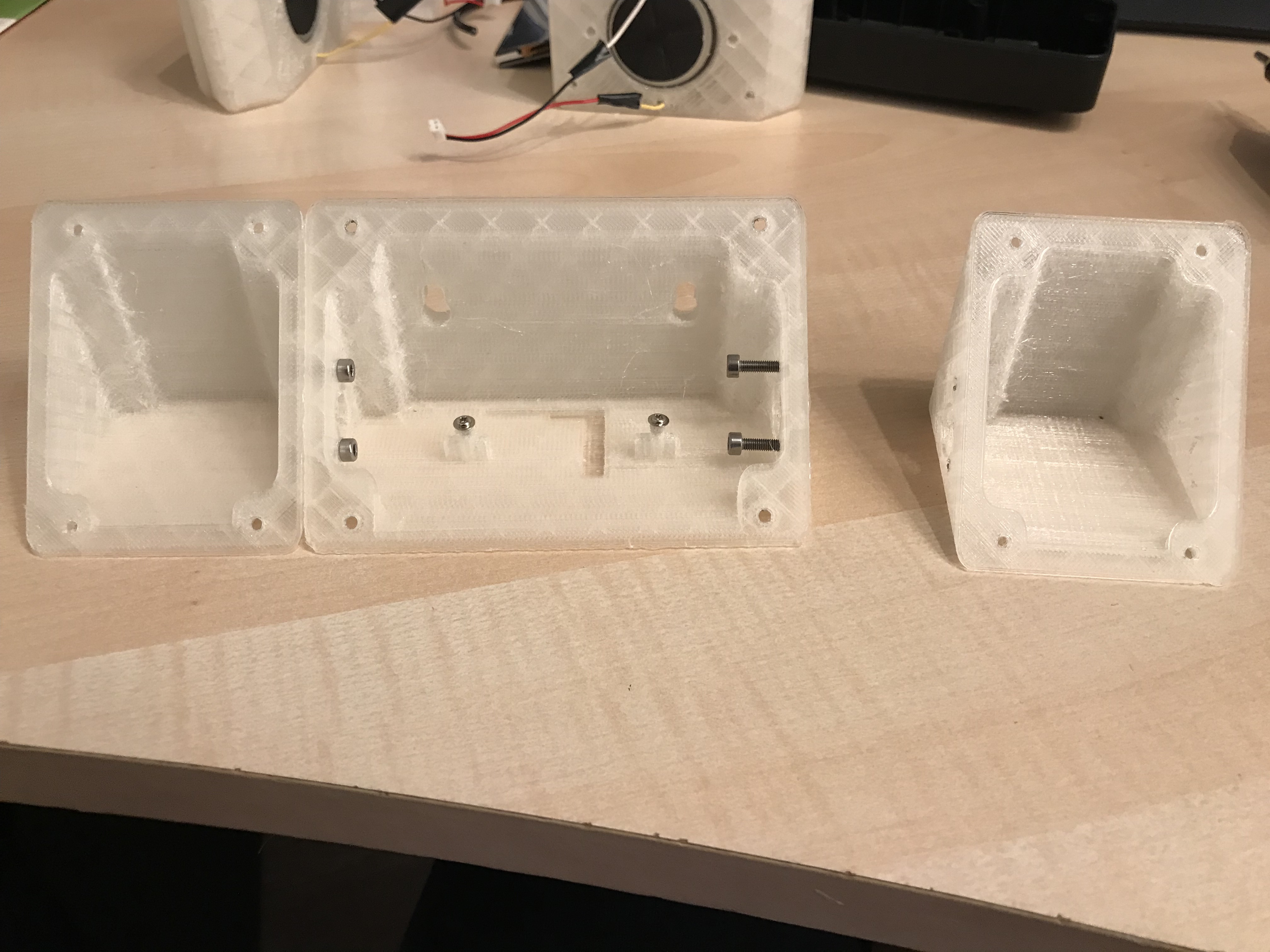
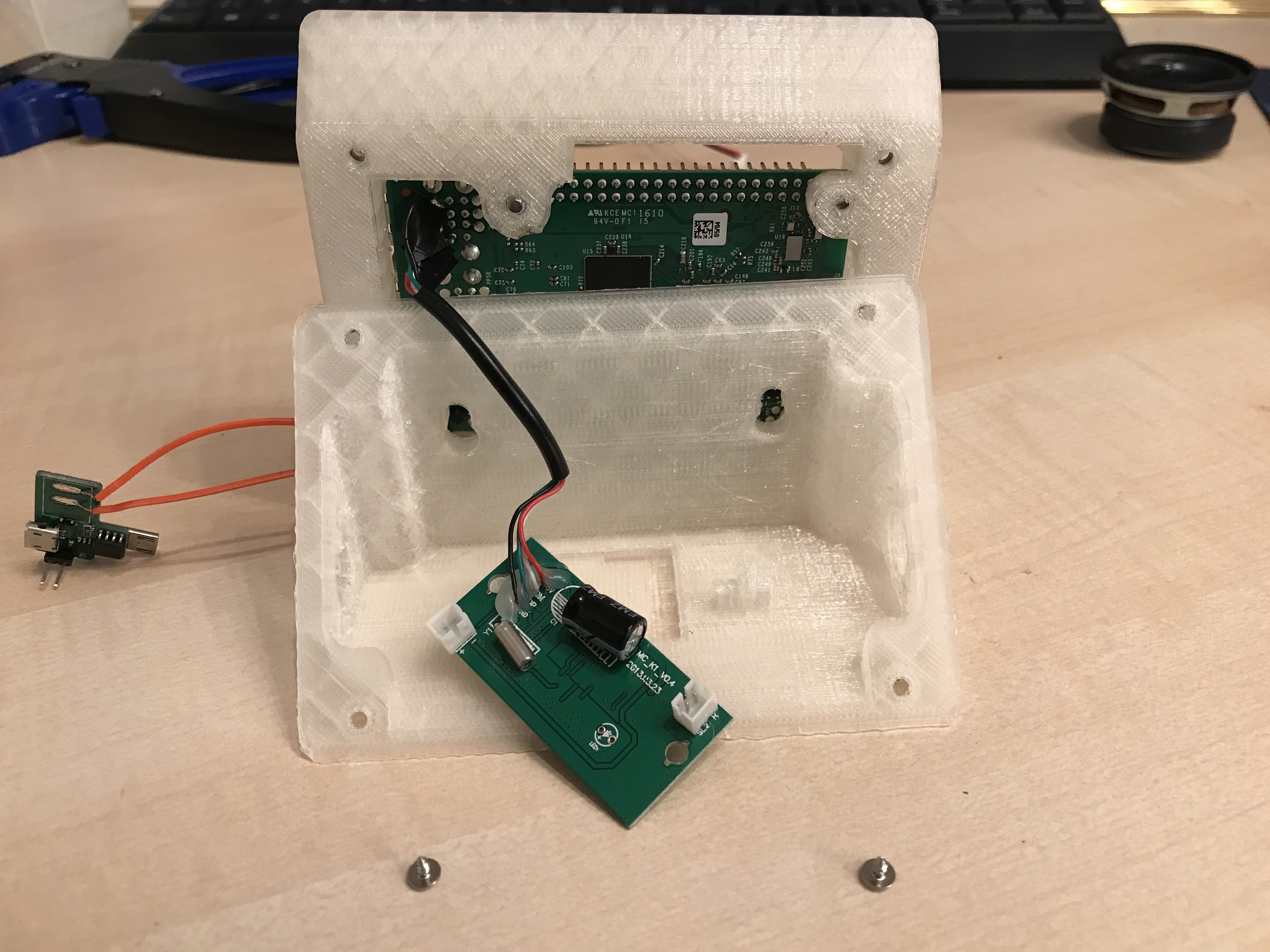
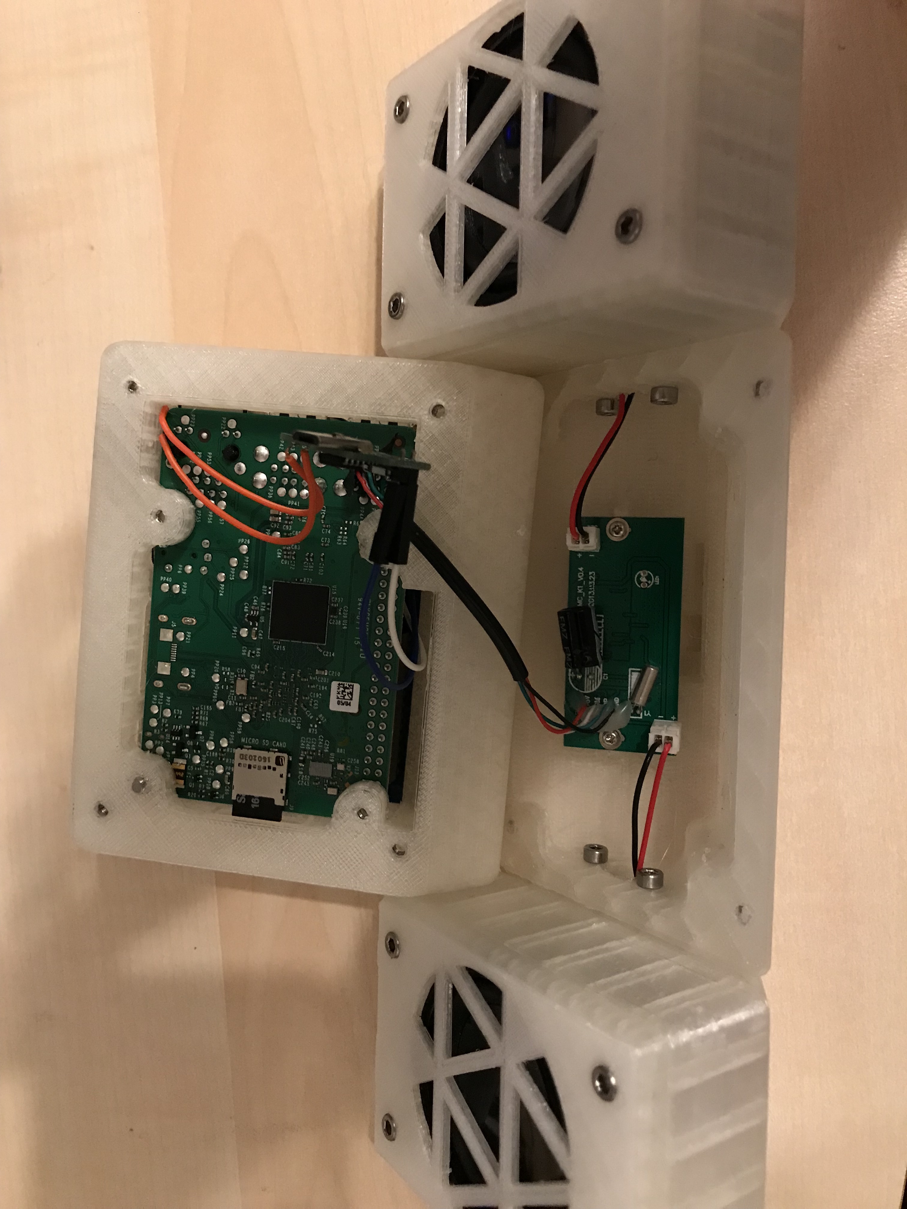
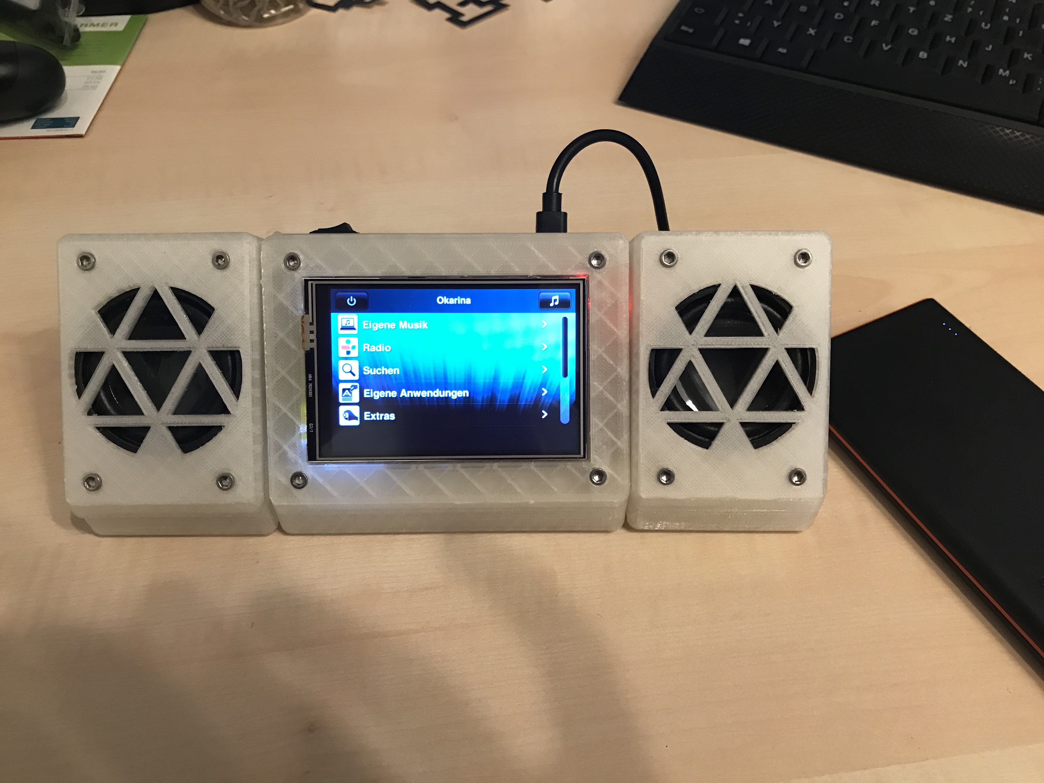
The final construction is a bit fiddly, but with long enough wires everything should fit.
The speaker casing was a bit on the small side, which together with the blown out nut housing on one side meant that the left speaker didn't close flush with the speaker grill.
The three backpieces can be connected to one another using M3 bolts. The bolts will cut a thread the first time you screw them in. As long as you don't take them apart to often, this connection should be strong enough.
Glue the shutdown circuit board into the case and screw the soundboard onto the standoffs.
The Raspberry Pi can be fastened to the middle casing with M3 bolts. Make sure to insert the SD card after screwing the Pi in place, as it is slightly larger as the casing. It can be inserted afterwards using a pair of tweezers, through the opening in the side.
After adding the touchscreen, all that remains is screwing the front plate in place.
I didn't have a micro USB cable on hand before completing the build, so I am temporarily powering the Pi though the Pi's micro USB port using a power bank. I will add the missing cable connection at a later point.
I hope you enjoyed this mini jukebox build. I look forward to testing this out over the next couple of weeks. If you have any questions or improvement ideas, leave me a comment down below and I'll try to get back to you as soon as possible