Raspberry Pi Pico and HC-05 Bluetooh
by Ramatronics Laboratory in Circuits > Raspberry Pi
1120 Views, 3 Favorites, 0 Comments
Raspberry Pi Pico and HC-05 Bluetooh
In this project I am going to interface an HC-05 module with Raspberry pi pico to add Bluetooth control functionalities in our Raspberry pi pico projects. For example, here in this instructables I going to make on and off the built-in LED of Raspberry pi pico Using my Android mobile phone. Awesome! Let's get started.
Supplies
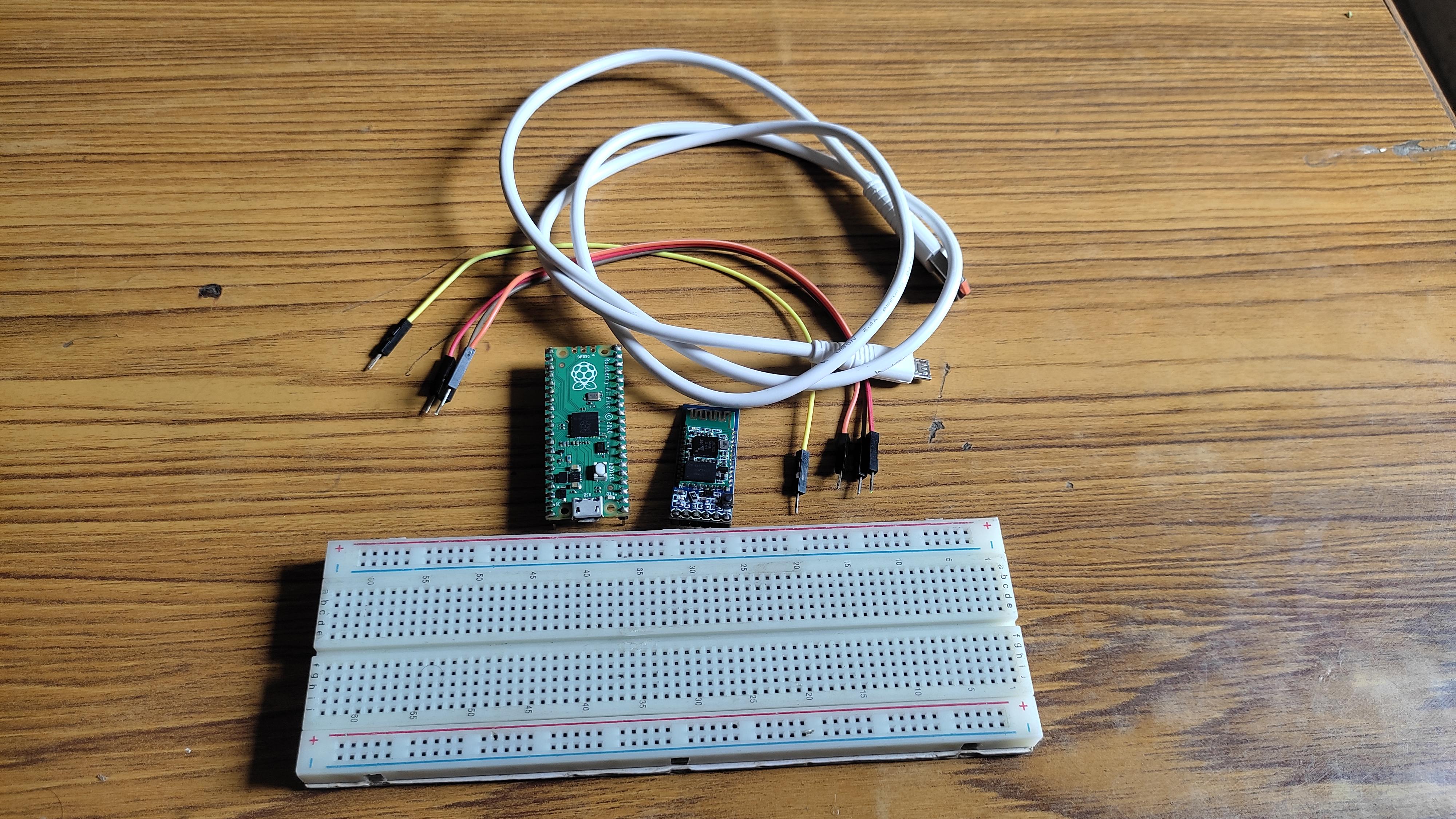
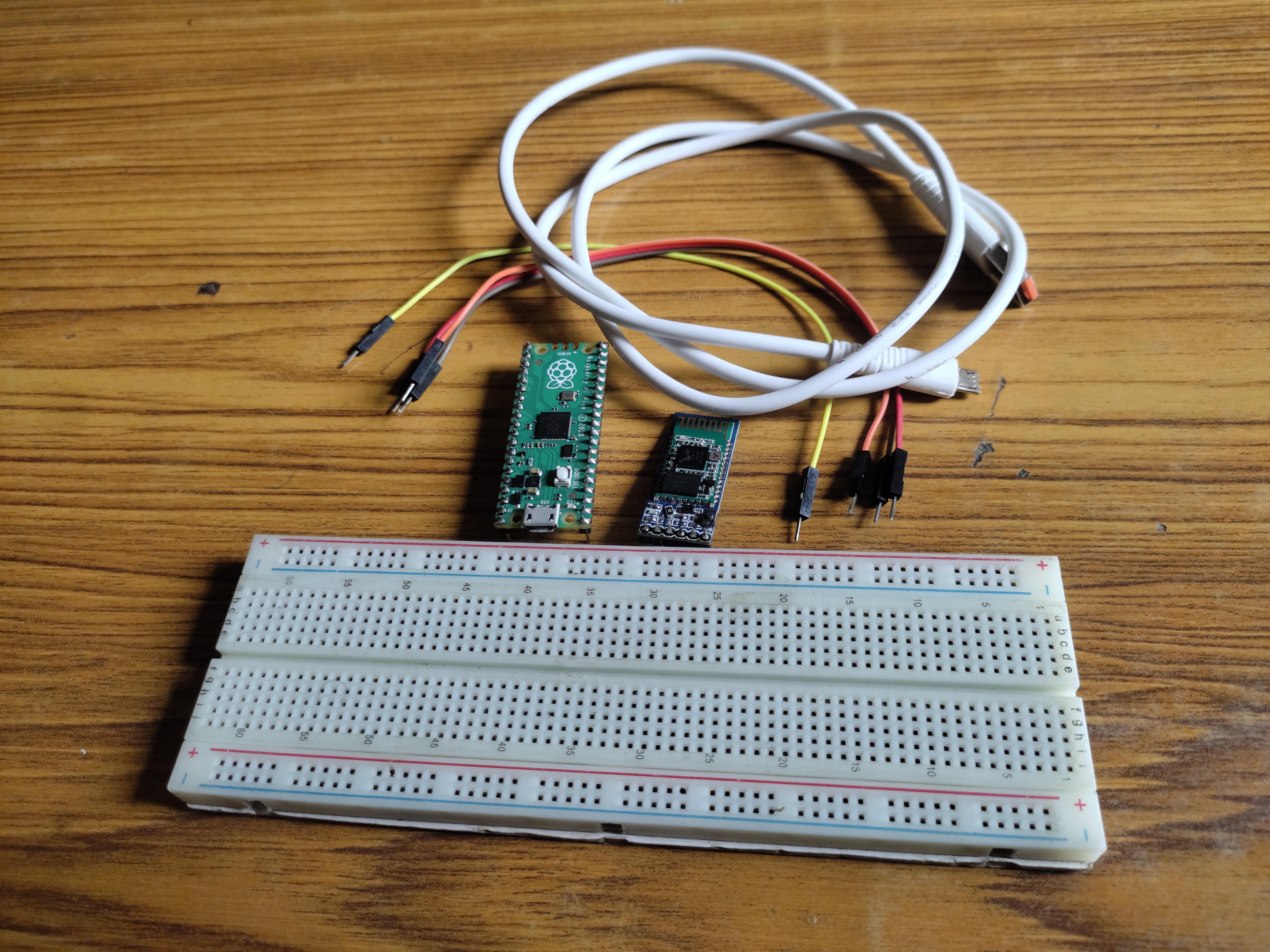
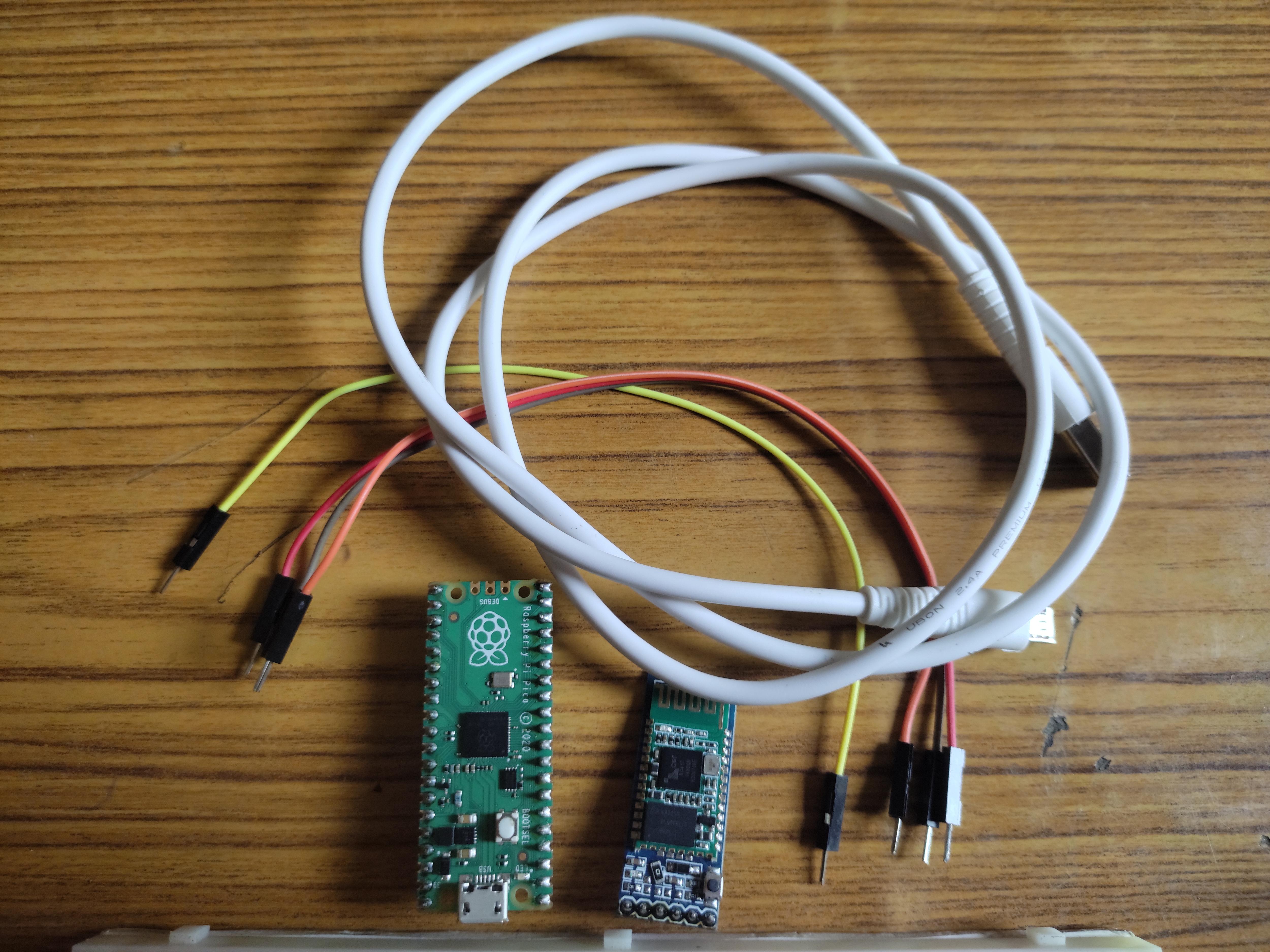
Hardware List:
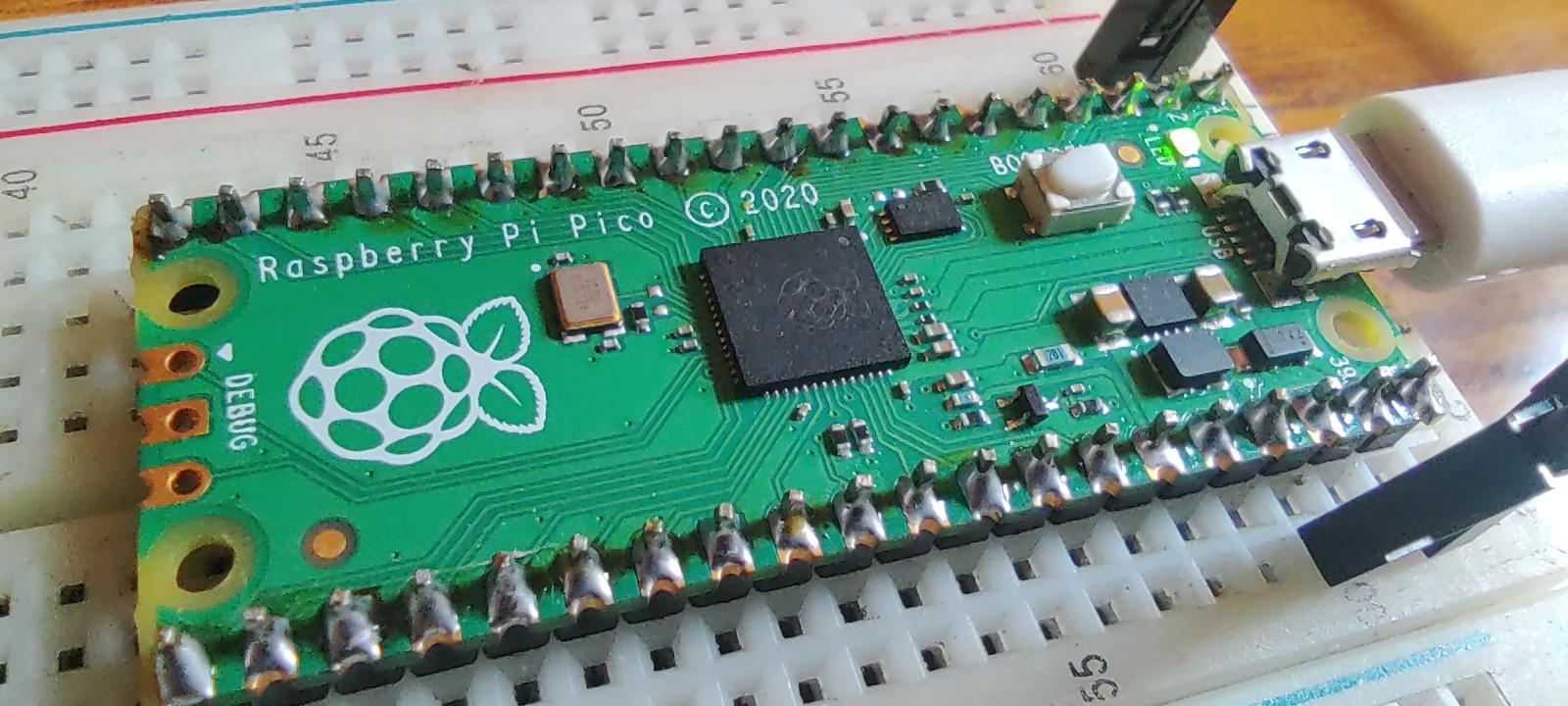
Raspberry pi pico
https://www.amazon.in/REES52-Raspberry-microcontroller-Development-RP2040/dp/B08V4XBDDB/ref=sr_1_5?crid=JR0K6YE2PXUD&keywords=raspberry+pi+pico&qid=1658657038&sprefix=raspberry+pi+pico%2Caps%2C289&sr=8-5
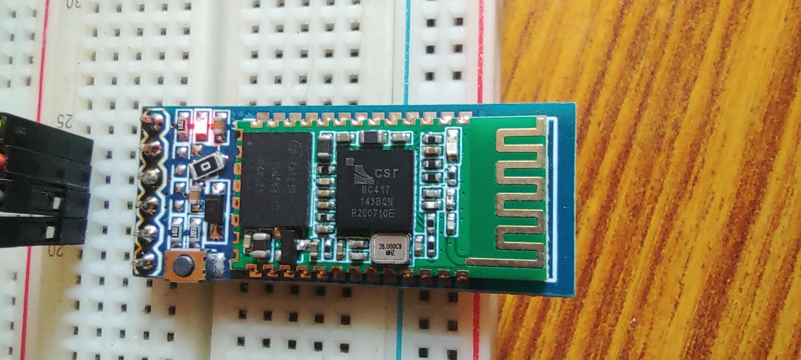
HC-05 Bluetooth module
https://www.amazon.in/TechSupreme-Wireless-Bluetooth-Transceiver-Security/dp/B09L7885GD/ref=sr_1_13?crid=DPDOC57THSO9&keywords=hc05+bluetooth+module&qid=1658657123&sprefix=hc05%2Caps%2C705&sr=8-13
Bread board
https://www.amazon.in/Robotbanao-Solderless-MB102-Breadboard-Points/dp/B08GG6ZC41/ref=sr_1_32?crid=3J6ZH91AIKOY7&keywords=Bread+board&qid=1658657206&sprefix=brea%2Caps%2C2160&sr=8-32
Jumper wires(male to male)
https://www.amazon.in/ESTALLION-Jumper-Wires-breadboard-jumper/dp/B09PBDRT7P/ref=sr_1_2_sspa?crid=2AFV3NGXV0Z5I&keywords=male%2Bmale%2Bjumper%2Bwire&qid=1658657314&sprefix=male%2Bmale%2Caps%2C607&sr=8-2-spons&spLa=ZW5jcnlwdGVkUXVhbGlmaWVyPUEzRFZLVVAyOTNPRkdZJmVuY3J5cHRlZElkPUEwMzg0NzEzMTlDMEE3WFhBMU9TTSZlbmNyeXB0ZWRBZElkPUEwMjkwOTg2MVRQTzJNMk1POUlMRCZ3aWRnZXROYW1lPXNwX2F0ZiZhY3Rpb249Y2xpY2tSZWRpcmVjdCZkb05vdExvZ0NsaWNrPXRydWU&th=1
Android smart phone
Making the Circuit on a Breadboard
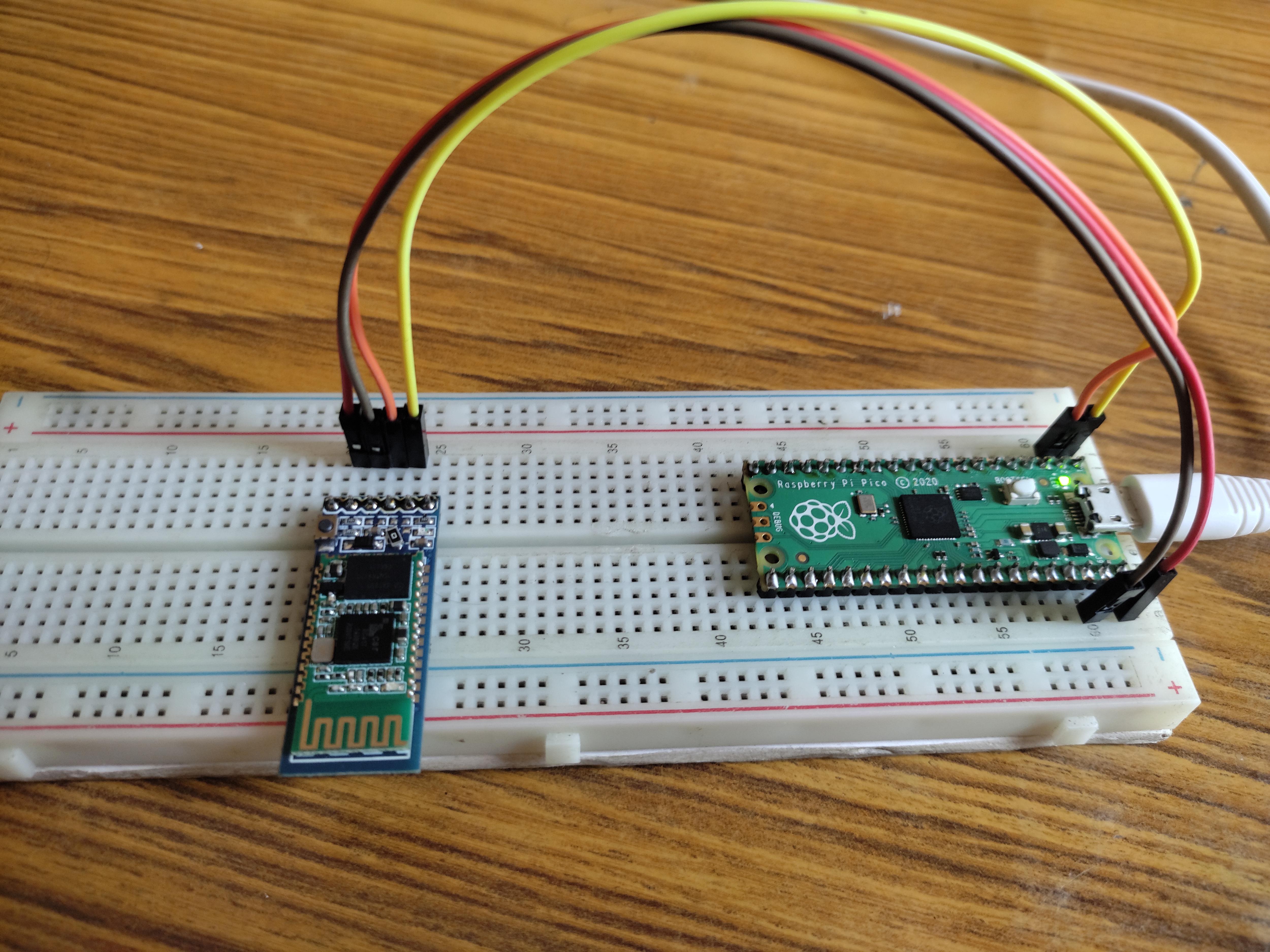
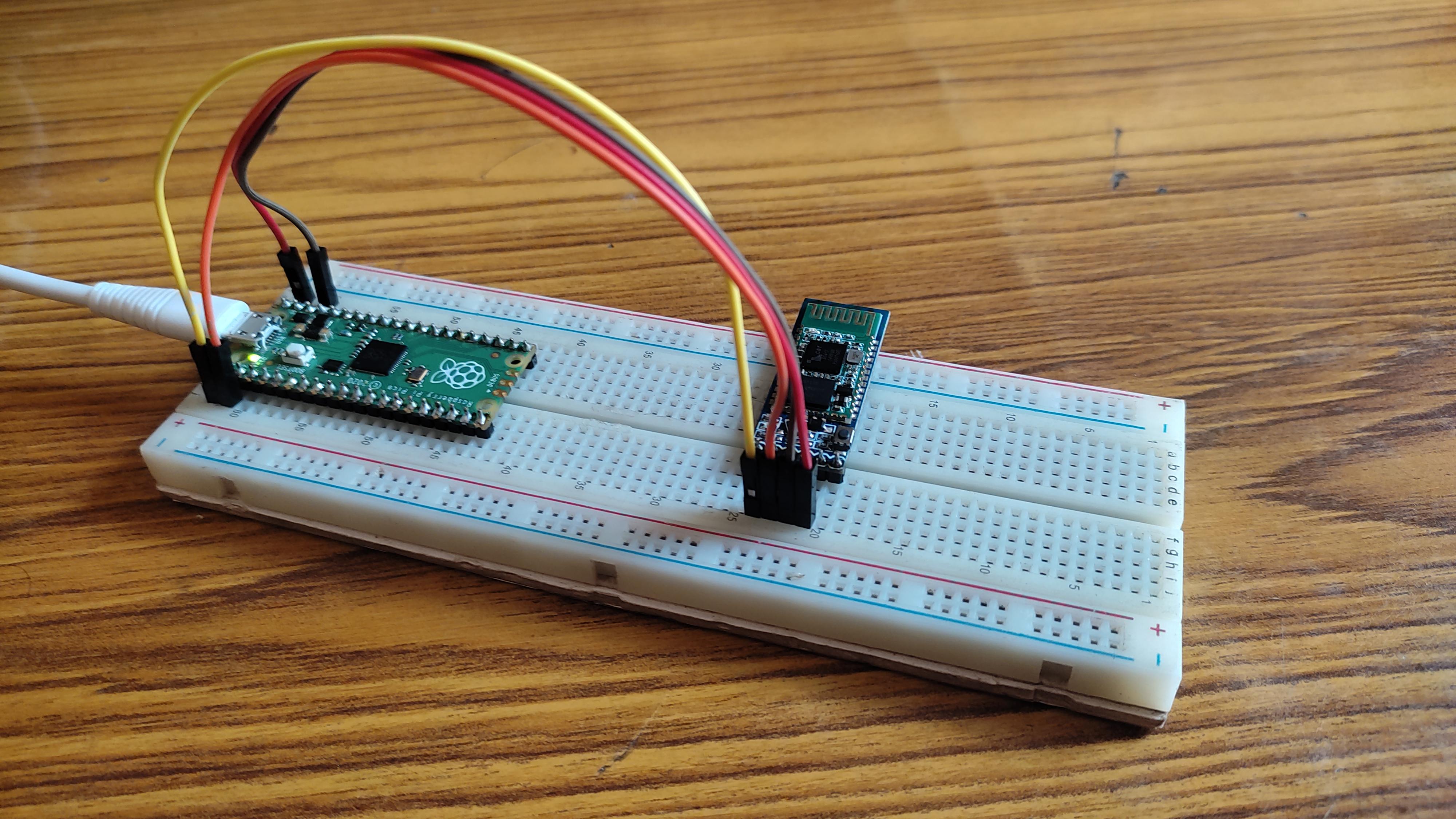
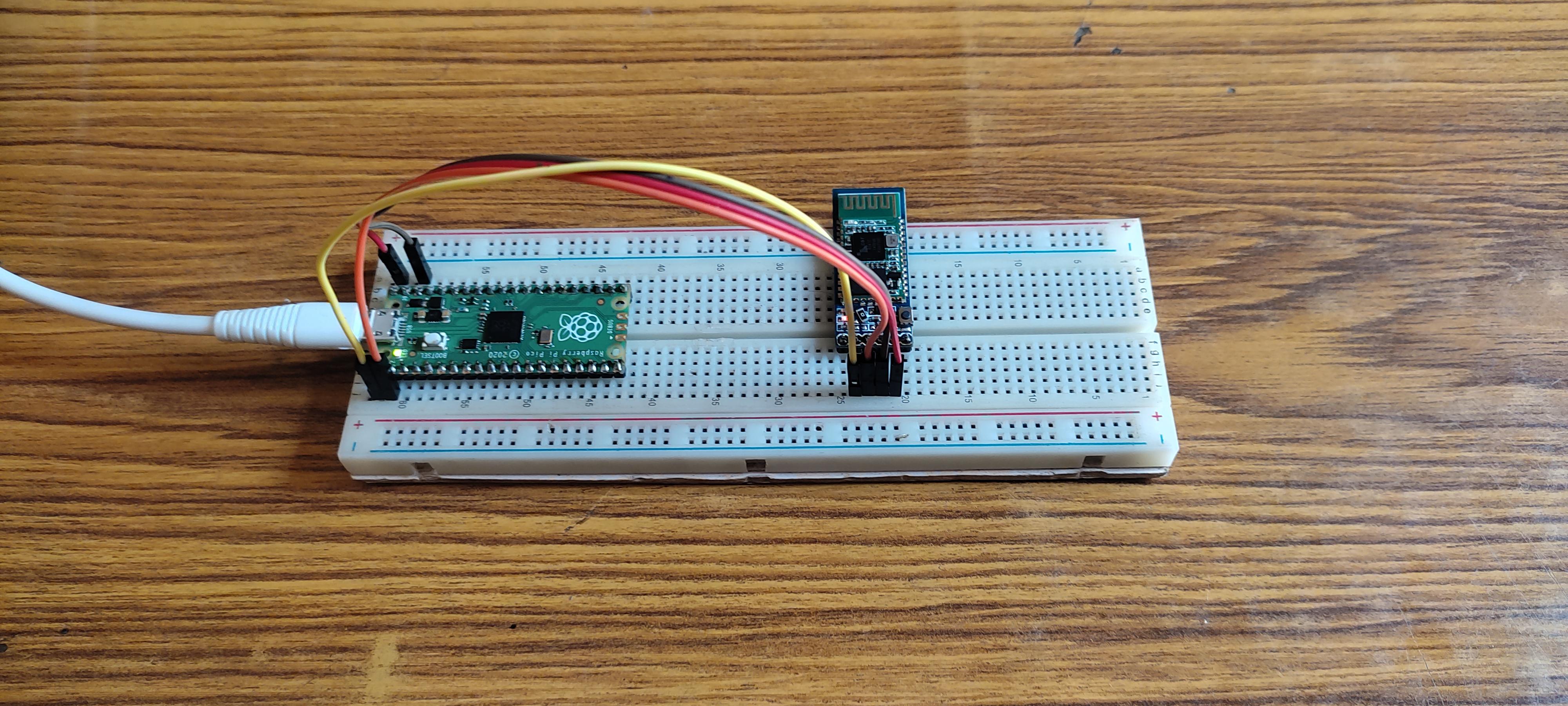
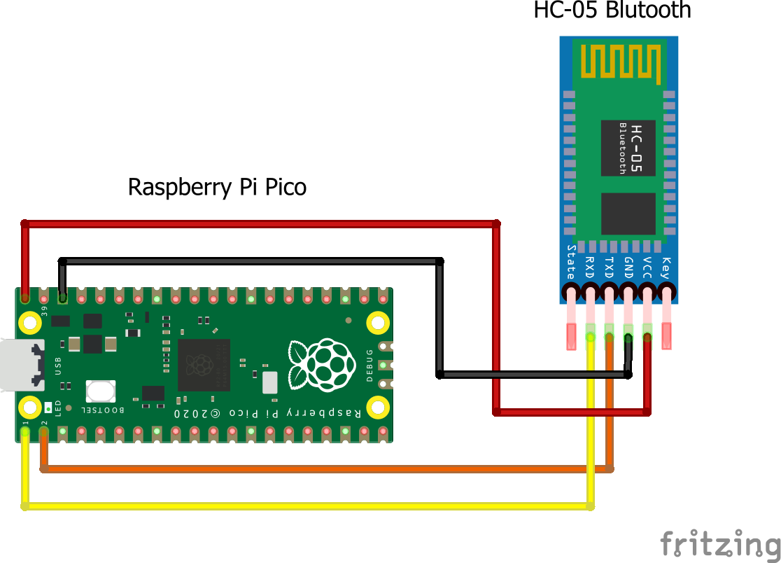
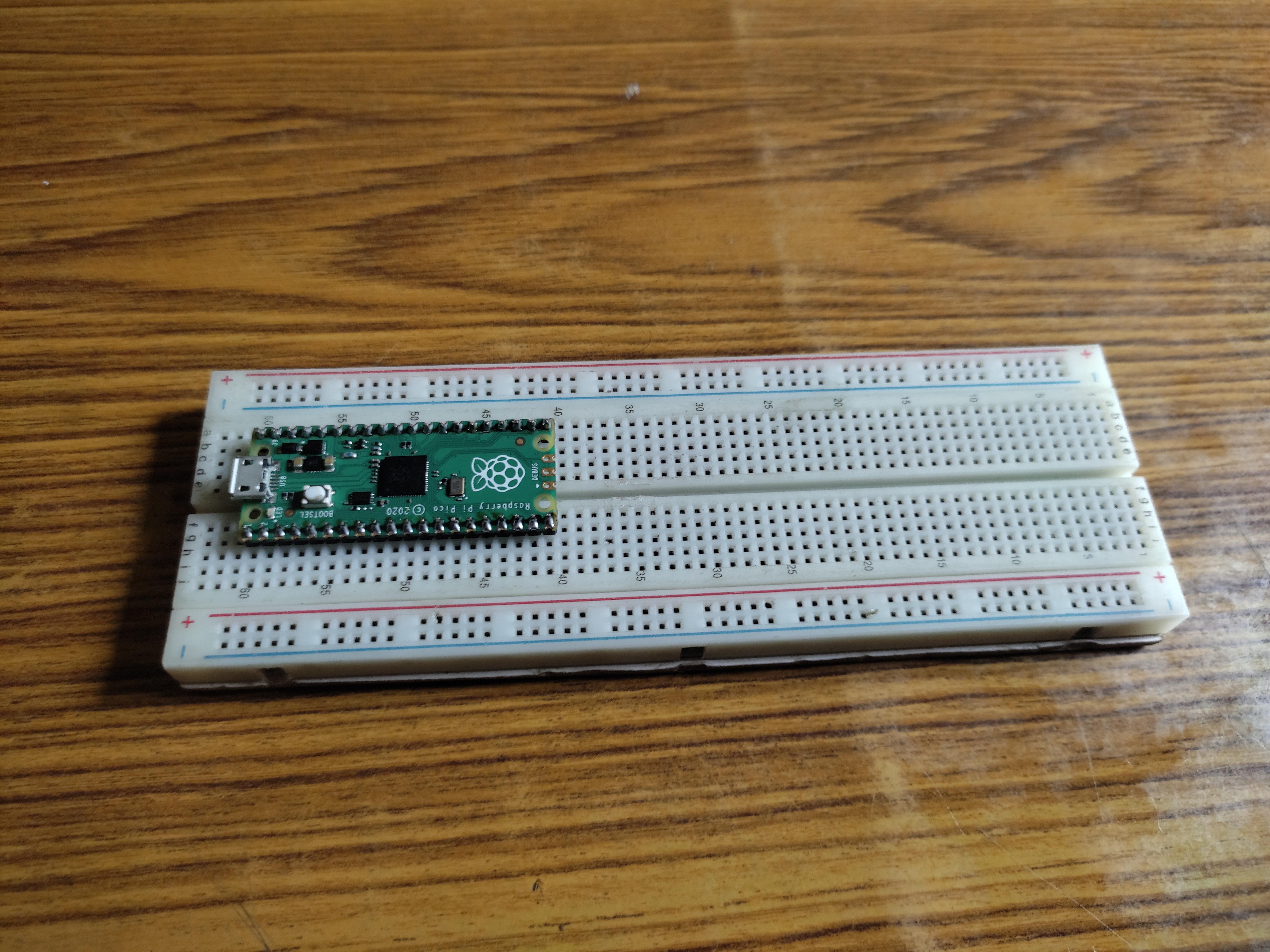
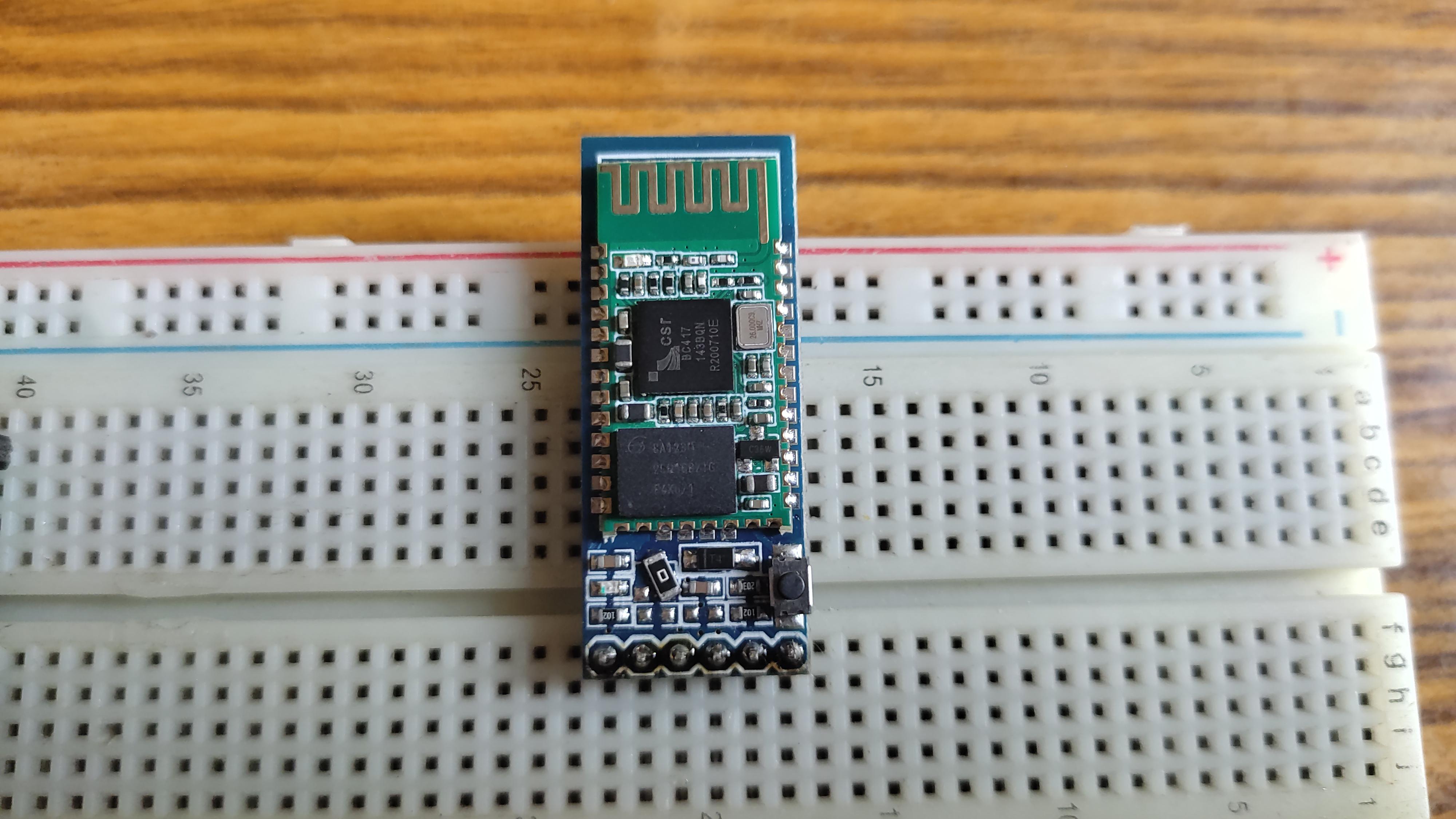
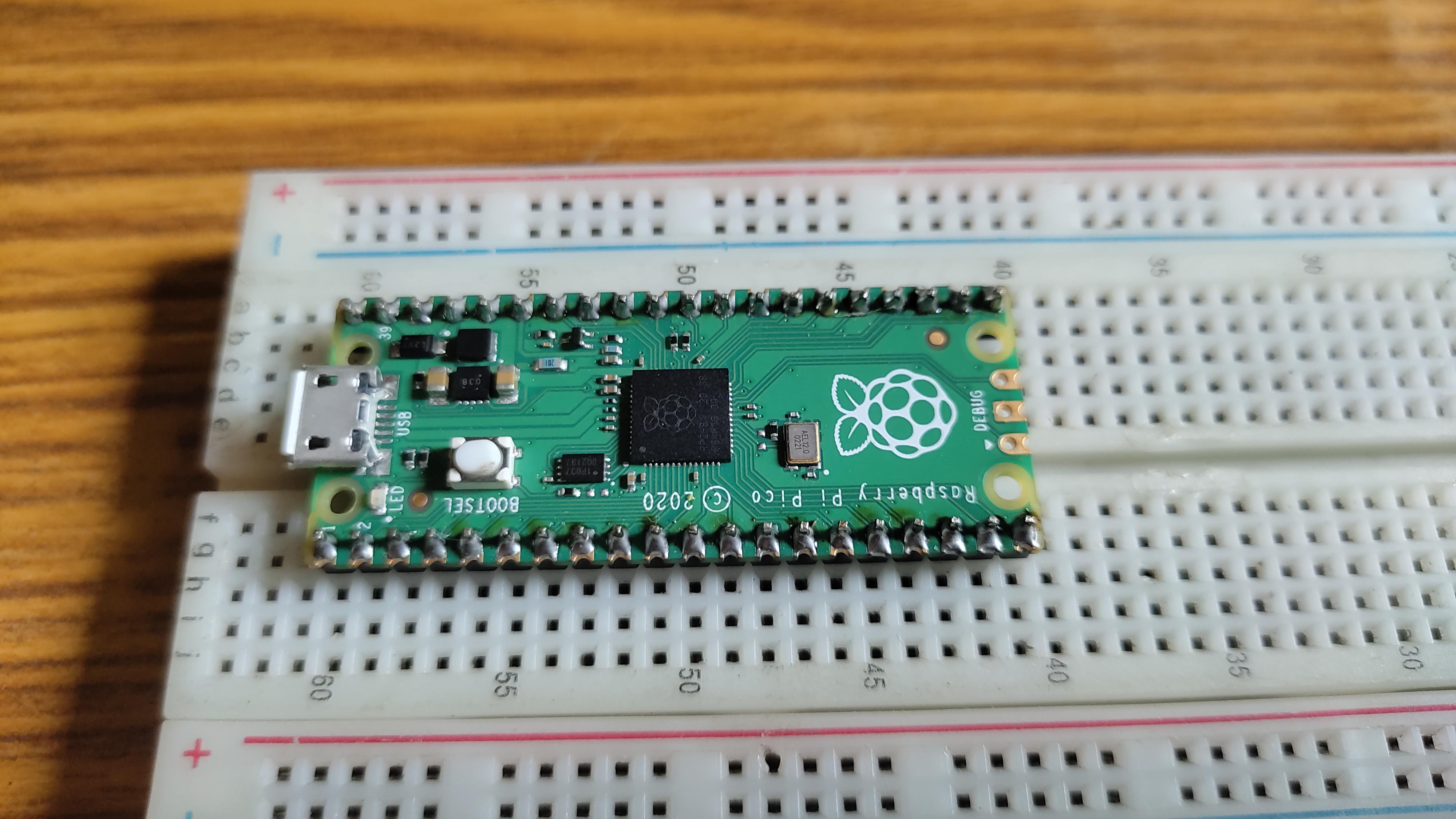
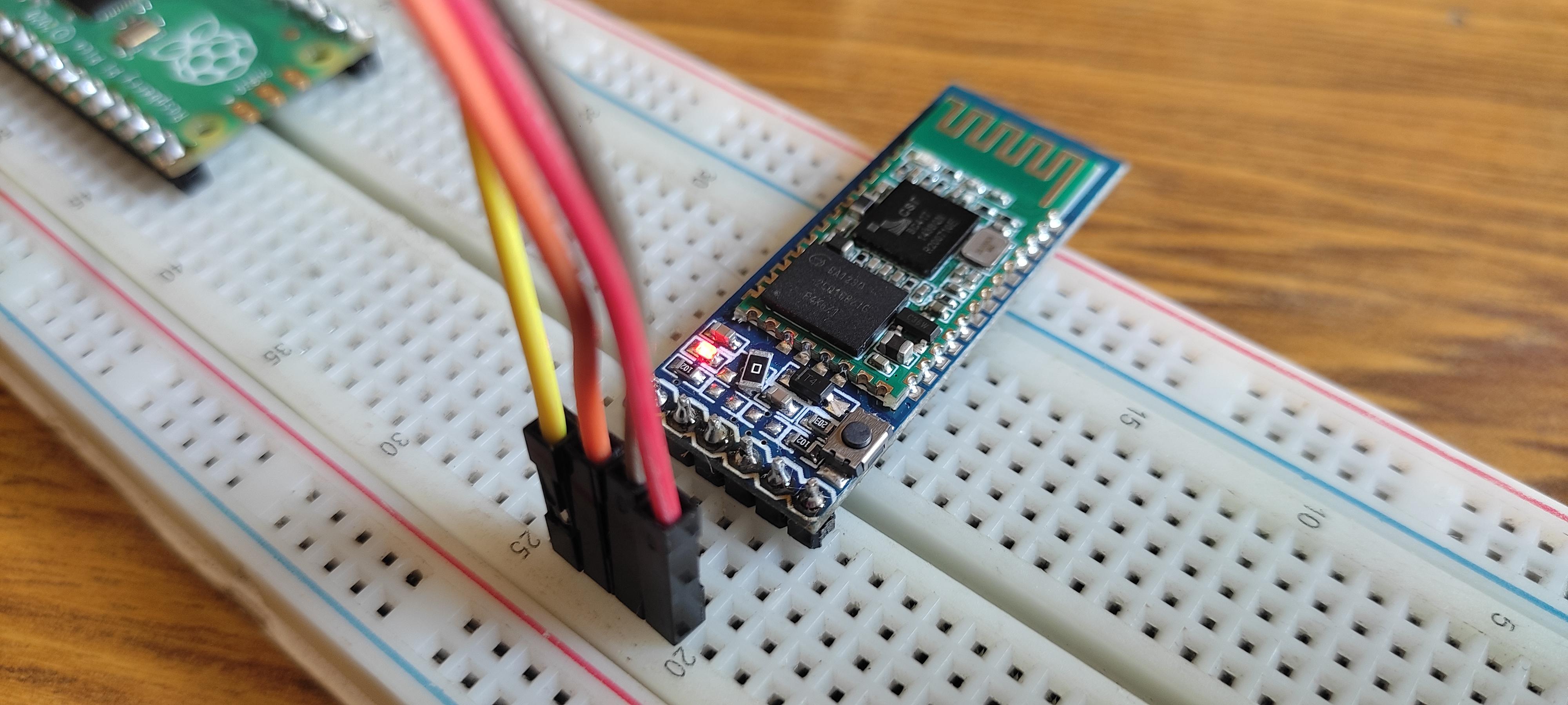
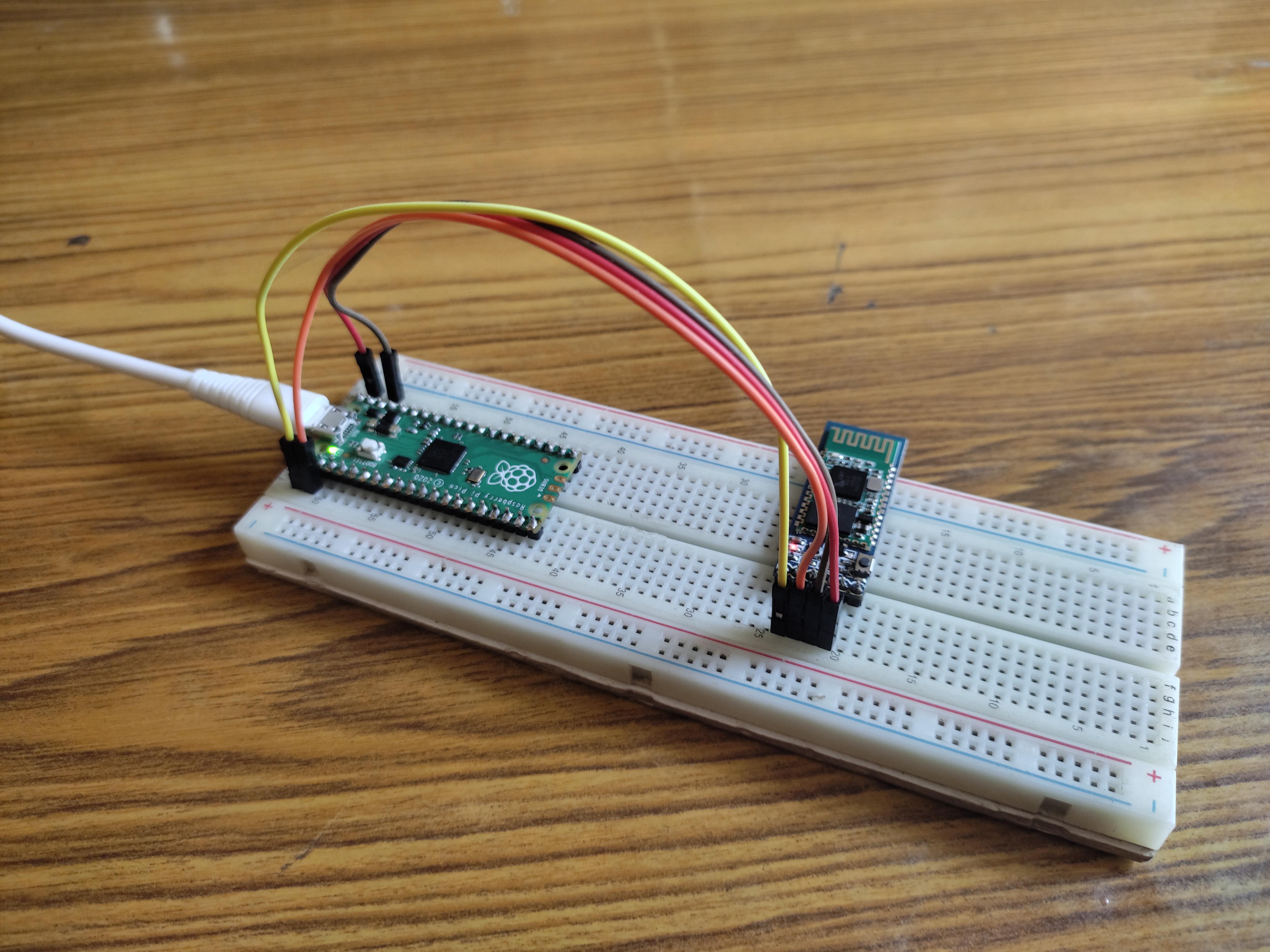
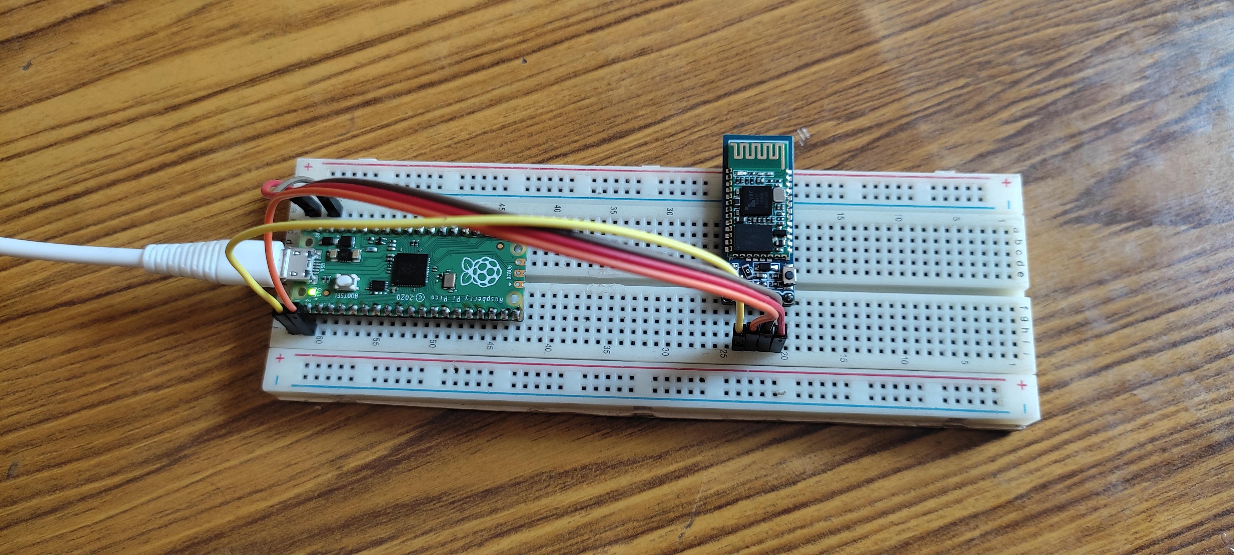
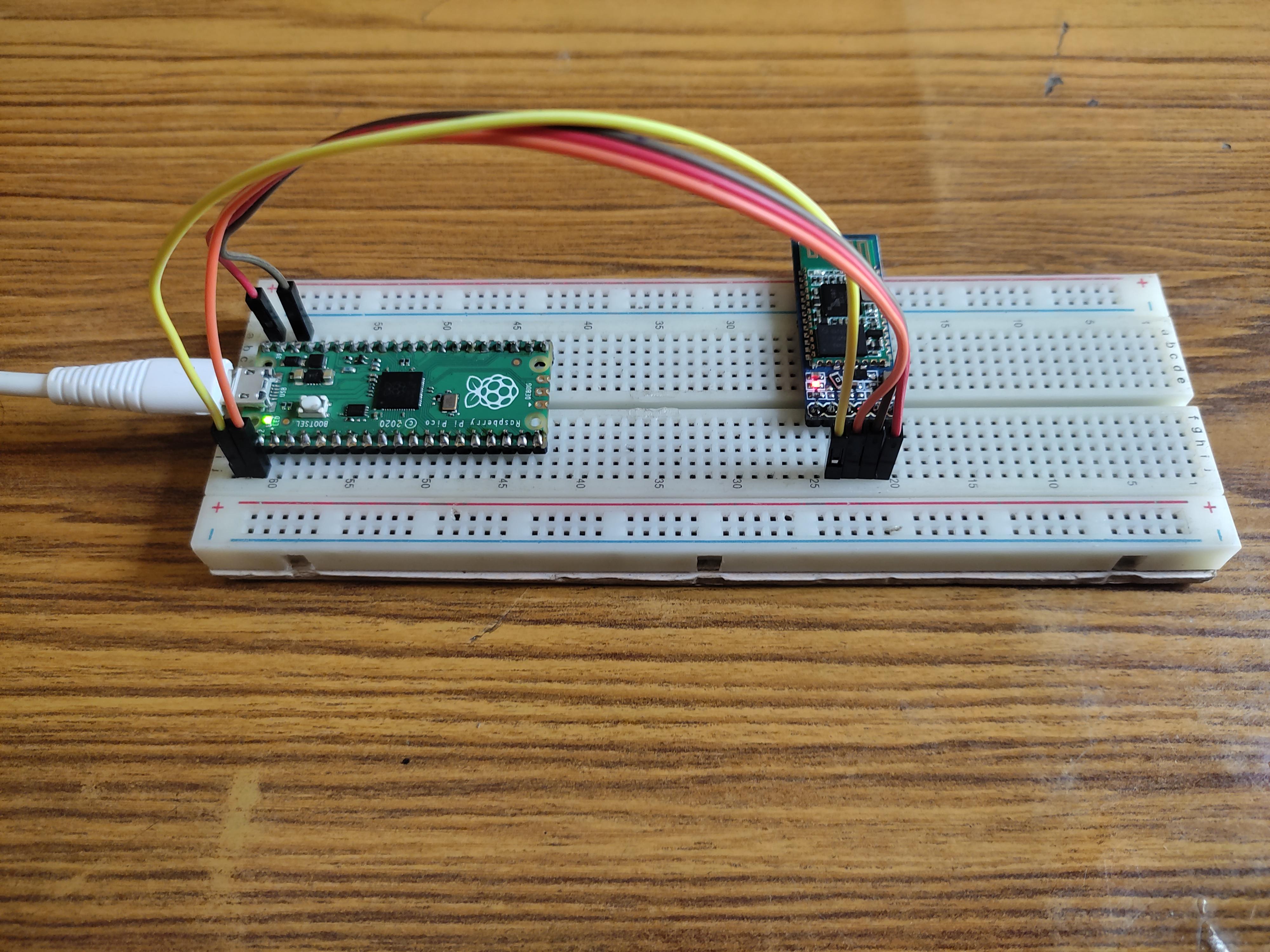
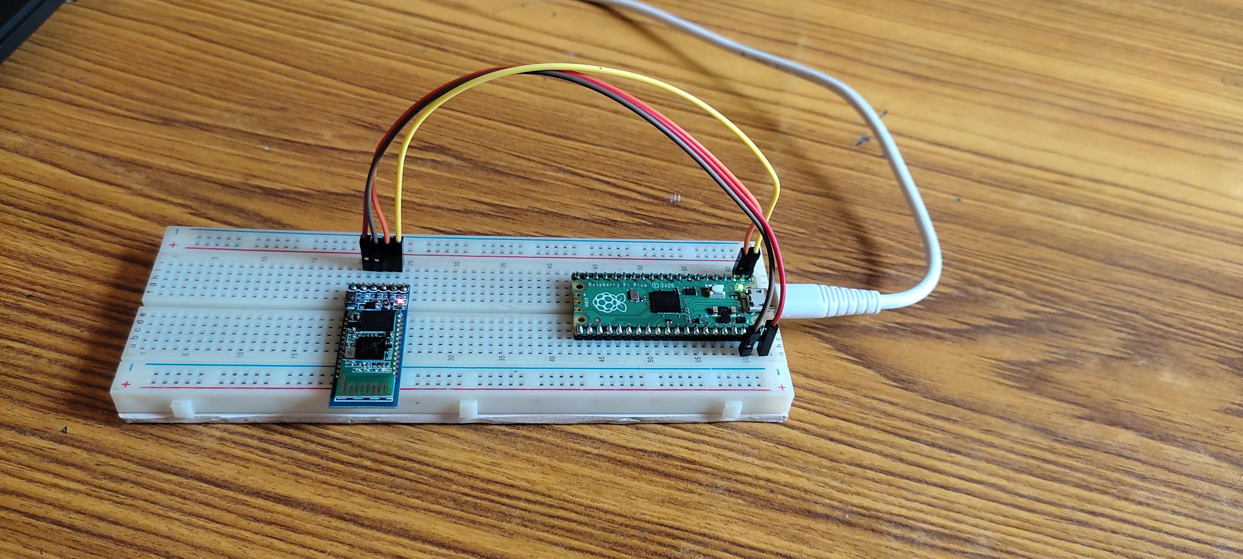
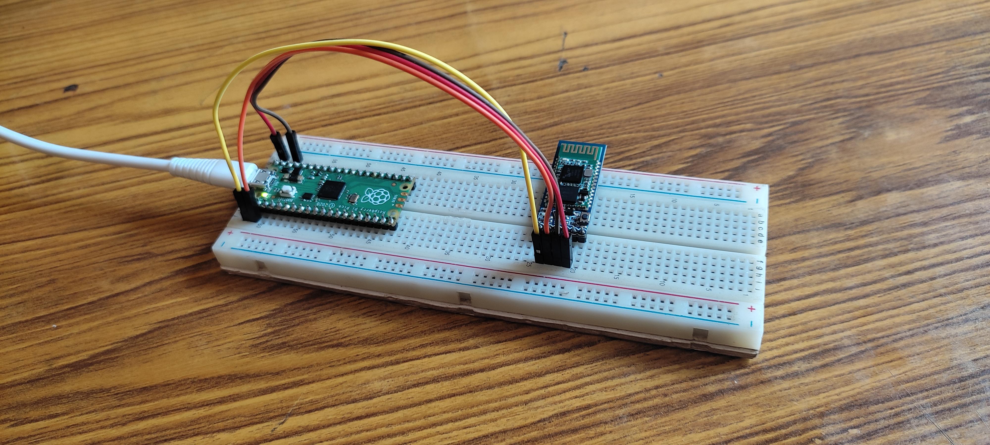
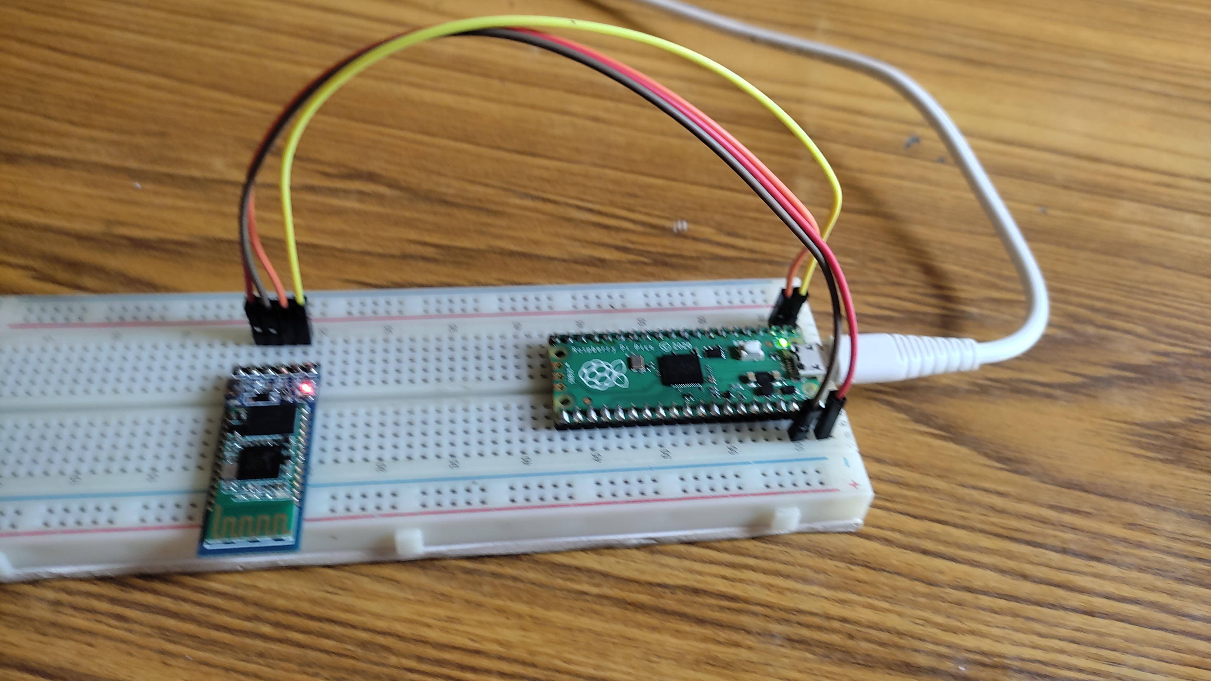
In step first, Insert the Raspberry pi pico and HC-05 Bluetooth module in the bread board as shown in the above given pictures. Now connect the HC-05 module with Raspberry pi pico using male to male jumper wires. For making proper connections, you can take the help of the given diagram or following wiring Scheme.
Vcc -------> VBus
GND --------> GND
TX ----------> GPIO-1
RX ----------> DPIO-0
Warning - After making all the wiring connection between pico and HC-05 bluetooth module, please recheck all the connection twice and more to avoid the occurrence of wiring error otherwise your Raspberry pi pico and HC-05 may damage permanently. After rechecking all the connection, connect your pico board to your laptop or computer using Micro-B USB cable. Now the LED on the HC-05 starts blinking. This blinking LED indicates that HC-05 is now ready to pair.
Installing App on Your Android Form

.png)
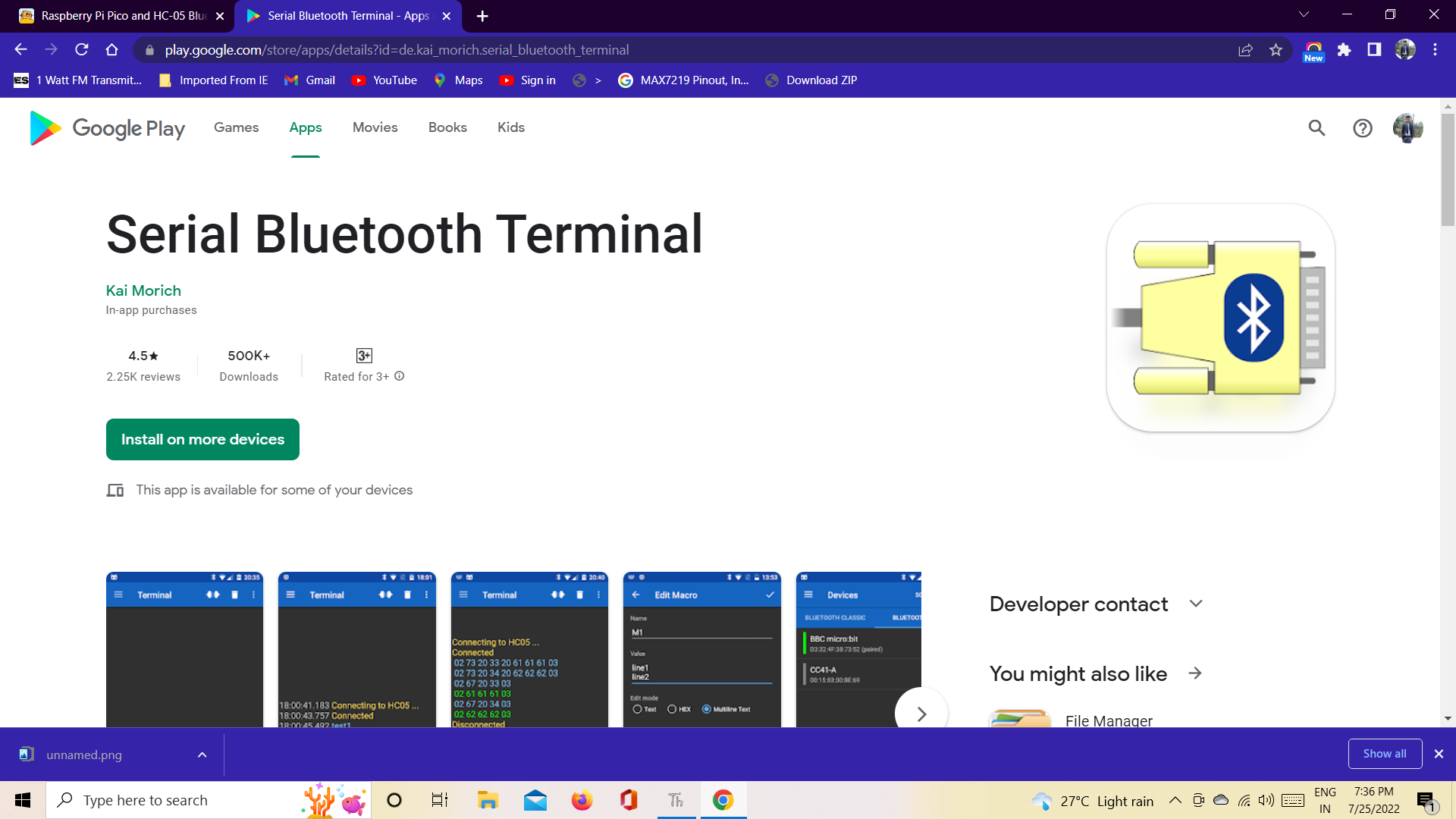
In the second step we have to install an app from play store. The name of the app is S2 Terminal. After downloading the app open the app on your android phone and Turn on the blutooth of your android phone and then in bluetooth click on search for new device and then you will see a device with name HC-05 will be there. Now click on this to pair and enter the password '12345' and click on OK now your HC-05 is paired with your android phone. Now open the S2 Terminal in your android phone and then on the top left corner of the screen you will see an option, click on this option and a list of options will appear on the screen and now choose the device and finally you have to choose your bluetooth device i.e. HC-05. Now you now S2 terminal will show that 'Connected'. Means we are now connected to HC-05 Module.
Programming
.png)
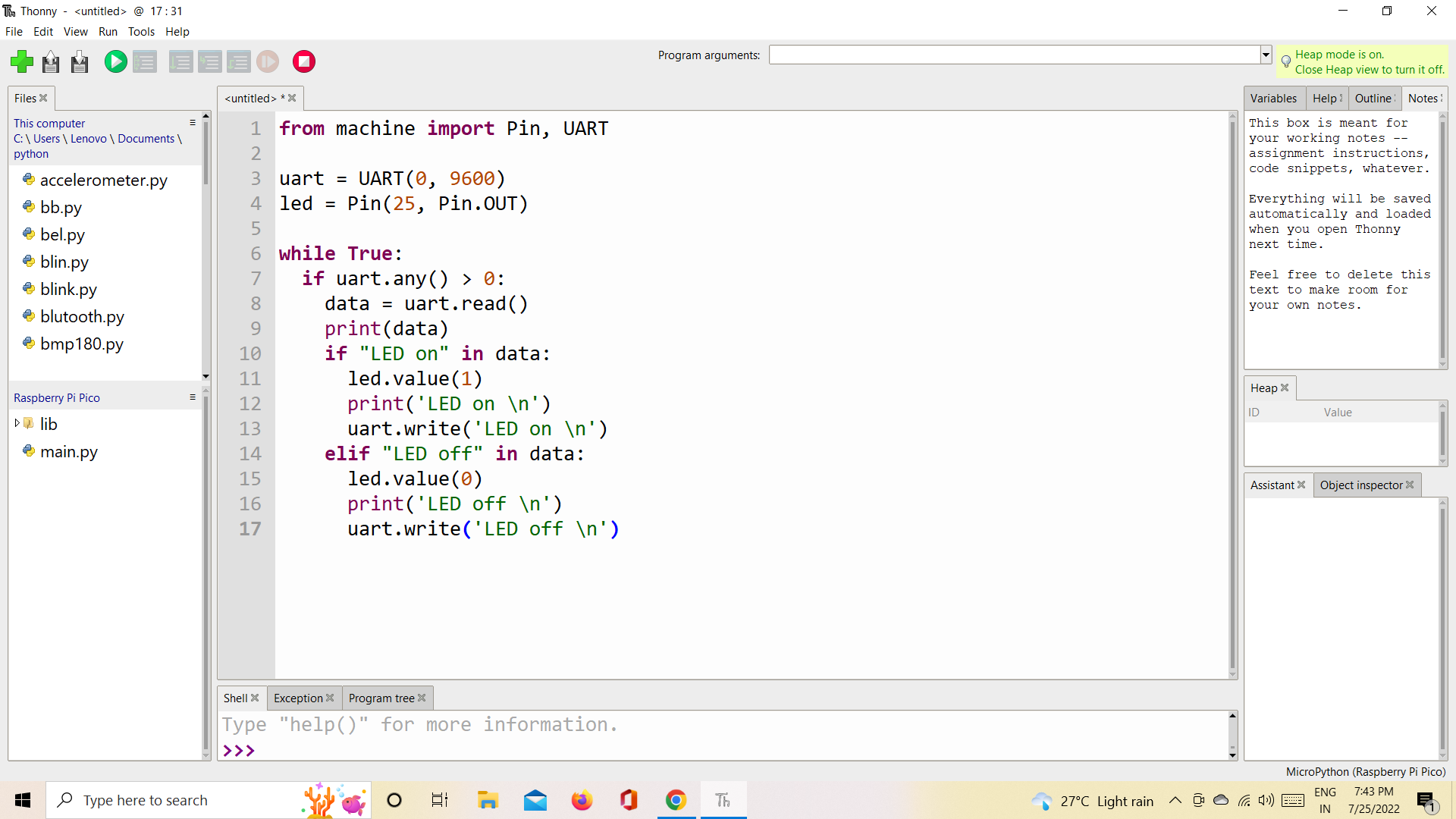
To program your pico board, Open Thonny on your laptop or computer and then click on Tool option and then choose options and then again select the interpreter and choose Micropython(Raspberry pi pico ) and also select the correct port on which your pico board is connected to. Open a new file In Thonny, Copy the python program given below and save this program on your Raspberry pi pico board with name 'main.py'.
from machine import Pin, UART

uart = UART(0, 9600)
led = Pin(25, Pin.OUT)

while True:
  if uart.any() > 0:
    data = uart.read()
    print(data)
    if "LED on" in data:
      led.value(1)
      print('LED on \n')
      uart.write('LED on \n')
    elif "LED off" in data:
      led.value(0)
      print('LED off \n')
      uart.write('LED off \n')
Testing
After saving the 'main.py' file in Raspberry pi pico, run this file and type 'on' on S2 Terminal and the press enter and your can see now than LED on the raspberry pi pico board starts flashing and pico board send the message "LED on" on S2 Terminal. Now again type 'LED off' and click on ok or enter. Now the LED on the pico board stops flashing. and you again see a new message "LED off" on S2 Terminal. It shows everything is working properly. now we are done here.
Thanks!
Pictures of My Work