Raspberry Pi Pico Tutorial
by James Crowfoot in Circuits > Microcontrollers
644 Views, 5 Favorites, 0 Comments
Raspberry Pi Pico Tutorial

Introduction
In this tutorial, I will guide you on how to start coding with the raspberry pi pico with micropython. I will walkthrough the code and explain what each section does and provide the full code at the end of each section.
Supplies
Supplies
Hardware
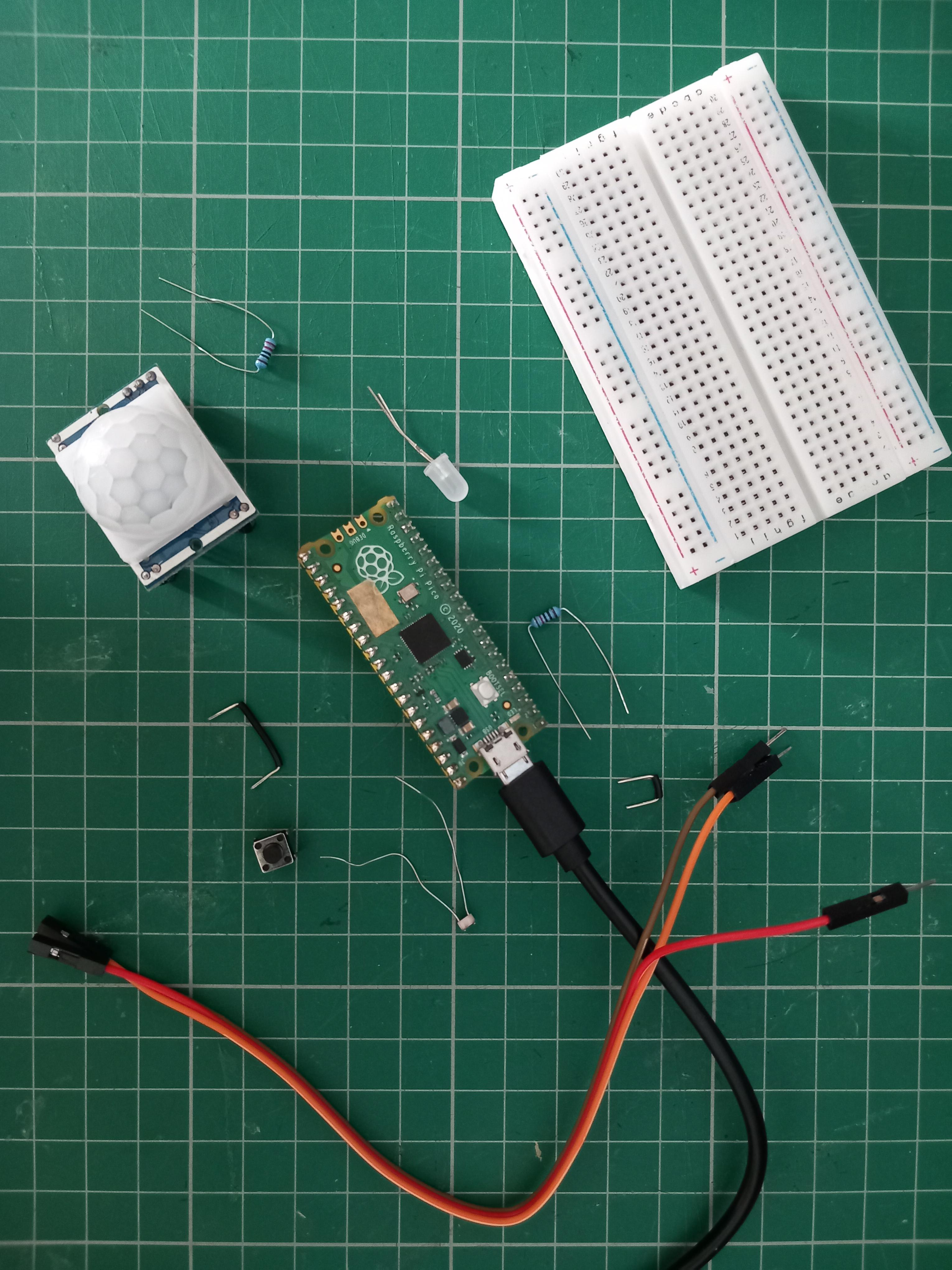
- Raspberry Pi Pico / Pico W or Raspberry Pi Pico 2 with headers.
- Computer that runs linux,mac os, or windows
- micro usb cable
Electronic components
- Breadboard
- Male to male jumper wires
- Male to female jumper wires
- LEDs
- Pushbuttons
- potentiometer
- Photoresistor
- PIR sensor
Software
Setup
Downloading the software
If you have not already got a compatible IDE (Integrated Development Environment) on your device, download one.
I will be using Thonny, It is a good python IDE for beginners and is FREE! You can download it here: Thonny, Python IDE for beginners
Setup of Thonny
Once you have downloaded Thonny, open it up and click "Run" on the menu bar at the top.
Next, click "select interpreter" and change it from "The same interpreter that runs Thonny (default)", to Micropython (Raspberry Pi Pico).
Setup the Raspberry Pi Pico
Download the UF2 file for your Pico here.
To program your device, follow these steps:
- Push and hold the BOOTSEL button while connecting your Pico with a USB cable to a computer. Release the BOOTSEL button once your Pico appears as a Mass Storage Device called RPI-RP2.
- Drag and drop the MicroPython UF2 file onto the RPI-RP2 volume. Your Pico will reboot. You are now running MicroPython.
Connecting to Thonny
While your Pico is plugged into your device, click the stop button in Thonny or Ctrl+F2.
If this does not work try unplugging it an plugging it back in.
We are ready to code! :D
Blinking an LED
Basic Blink
In this step we will learn to make an LED blink.
In Thonny, open a new file and save it as main.py
.py is the file extension for python files and main is just the name we have given it. main.py is a special file as it will always run as soon as the Pico gets power, but you don't need to worry about that for now.
The first line of code we will type is:
This imports the function Pin from the machine MicroPython library. The machine library is a fundamental library when coding with the raspberry pi pico. You will use to control the GPIO pins (General Purpose Input Output pins).
the next line is:
This imports the function sleep from the time python library, this will allow us to wait a certain about of time in our code.
Now we will define our LED, we will be using the inbuilt LED, which is located at Pin 25, we will do this by using the following code:
What this code is doing is it is defining the variable led as the pin 25 which we are also defining as an output pin.
now to make the led blink we will use the following code:
led.value(1 or 0) sets the state of the led to on (1) or off (0), sleep(number) makes the code wait that many seconds
your code should look like this:
now you can press the run code button (green circle with triangle in it) or press F5 to run the code.
your LED should blink once.
Loops
We will now learn a little bit about loops. There are two ways in which you can do a loop in python, a for loop or a while loop.
A for loop would look like this:
This code will loop 10 times and will list the numbers 0 to 10.
A while loop would look like this:
This loop will loop forever as it will loop while the statement is True. you can escape a while loop with break.
Blinking an LED in a loop
here are two ways to loop an led blinking:
For Loop ()
from machine import Pin
While loop (forever)
Downloads
Button Control LED

In this step you will also need a breadboard and pushbutton
Button Read
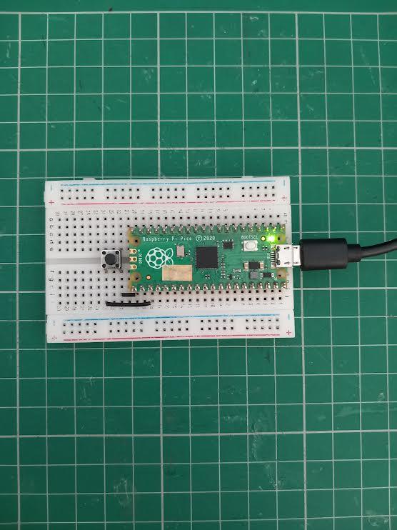
Wire up your Raspberry Pi Pico to a breadboard with a button, have one button pin going to ground and the other going to Pin 16.
First, we will import our libraries
Next, we will define our pushbutton
we have defined it as Pin.IN as we are reading its value, and we also add a pull up resistor by adding Pin.PULL_UP
we can now read its state by using
if it is equal to 1 then the button is not pressed and if it is 0 then it is pressed.
we can put this into a loop like so:
Button control LED
We will modify our existing code and circuit and add a LED controlled by the button.
I am going to use an external LED for this project, which I will plug into Pin 15, using a 220 ohm resistor. Pinout Diagram
we will add some lies of code to control the LED and this should be the result
Downloads
Reading a Potentiometer
To read resistance, we need to use a special type of pin called an Analogue to Digital Converter, or labelled as ADC on the pinout diagram. These pins are 26,27 and 28. we will use Pin 26.
use the code provided below
Photoresistor
We will use the same code we used for the potentiometer with the photoresistor, which changes resistance dependent on light.
Connect the photoresistor pins between Pin 26 and Ground
use the code below
Try covering the photoresistor with your hand or shining a light on it and watch the value change.
PIR Sensor
A PIR sensor stands for Passive Infrared Sensor. It can detect movement. It is commonly used in burglar alarms in buildings, commonly situated in the corner of a ceiling.
To wire this up we will connect VCC to 3v3 pin, GND to ground and OUT to pin 16
The code we will be using to utilise this component is:
Further Reading
If you want to learn more I recommend looking at the raspberry pi projects page to look at fun projects.
Hope this helped.
Thanks for reading!