Raspberry Pi Photobooth
by ArjunAtwal03 in Circuits > Raspberry Pi
860 Views, 1 Favorites, 0 Comments
Raspberry Pi Photobooth

The Purpose:
- Learn how to code and install a Pi Camera
- Using define and if statements in coding
- Learning to use new technology like the RGB LEDs
What You Will Need
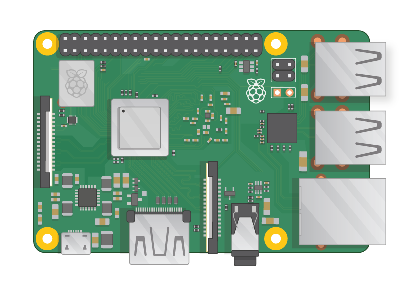
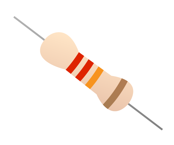
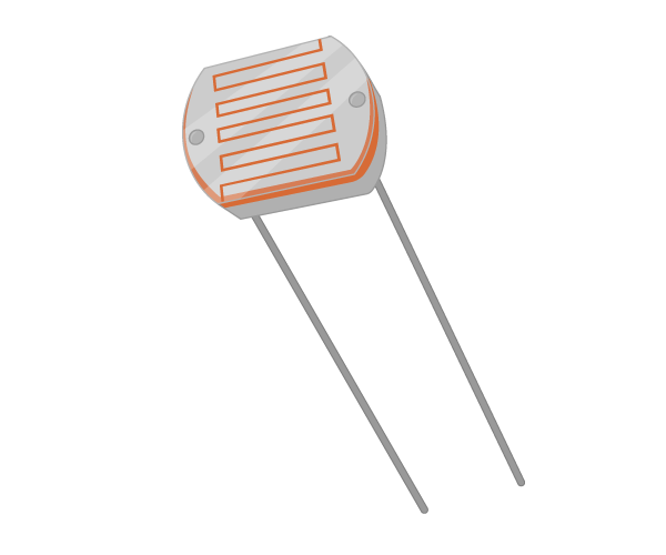
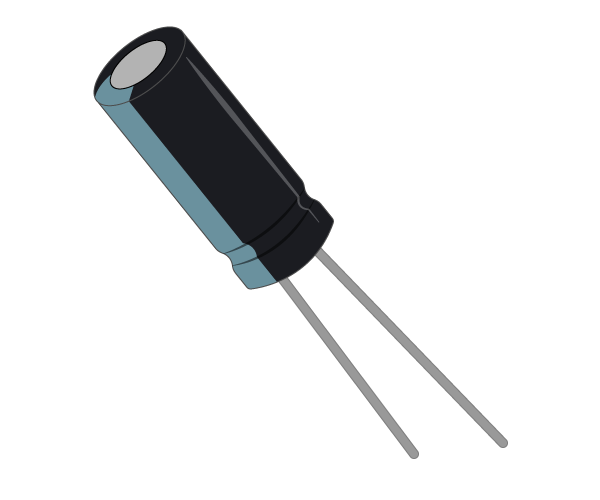
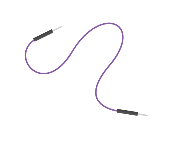
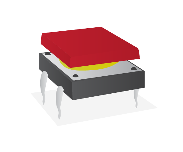
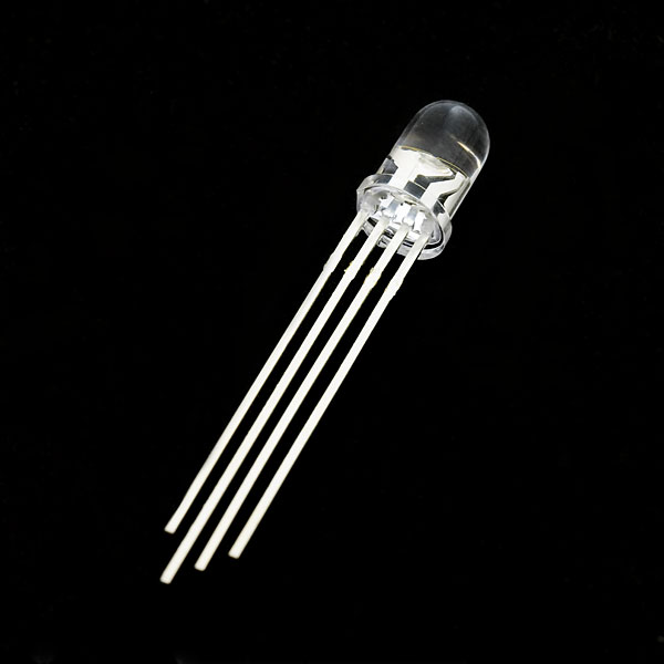
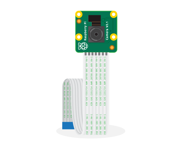
- 1 Raspberry Pi 3
- Breadboard
- Jumpers
- 1 Light Dependant Resistor
- 1 Capacitor
- 1 Push Button
- 6 220 Ohm Resistors
- 2 RGB LEDs
- 1 Raspberry Pi Camera
Connecting the Camera Module
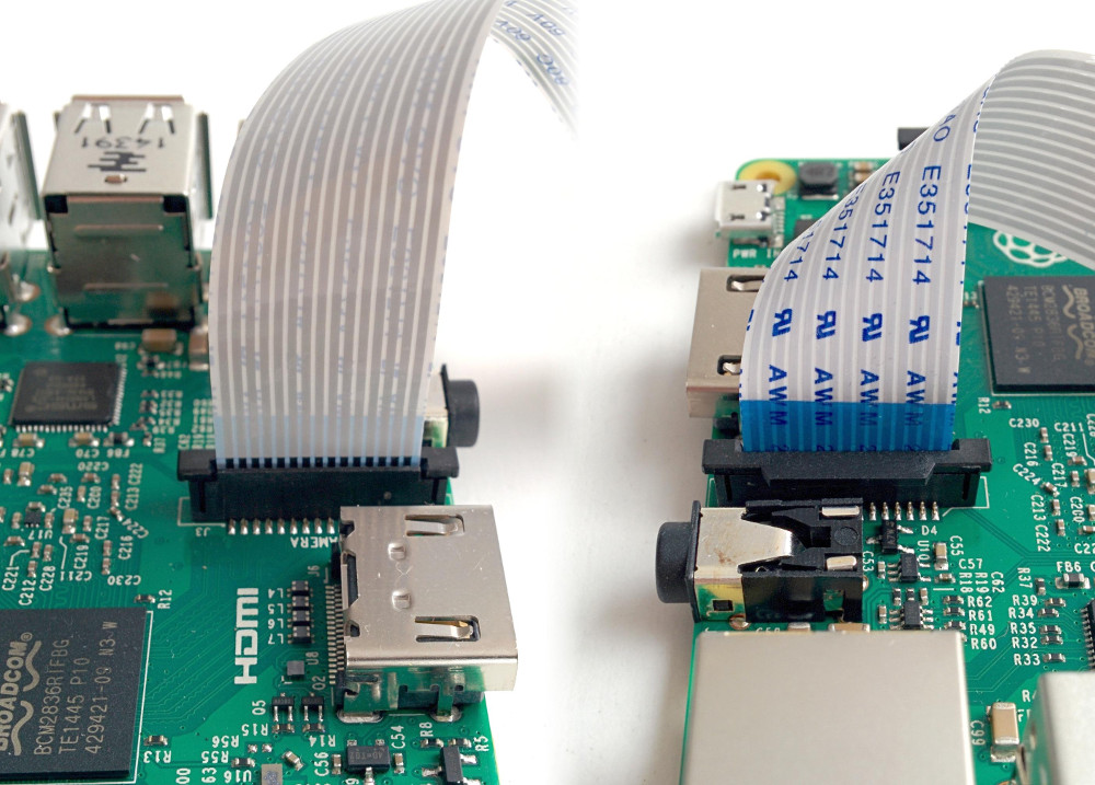
First of all, with the Pi switched off, you’ll need to connect the Camera Module to the Raspberry Pi’s camera port, then start up the Pi and ensure the software is enabled.
- Locate the camera port which is in between the HDMI and 3.5mm port
- Pull up the camera clip by the plastic edges until the clip is diagonal
- Now insert the cameras cable with the blue facing the 3.5mm port
Setting Up the Camera
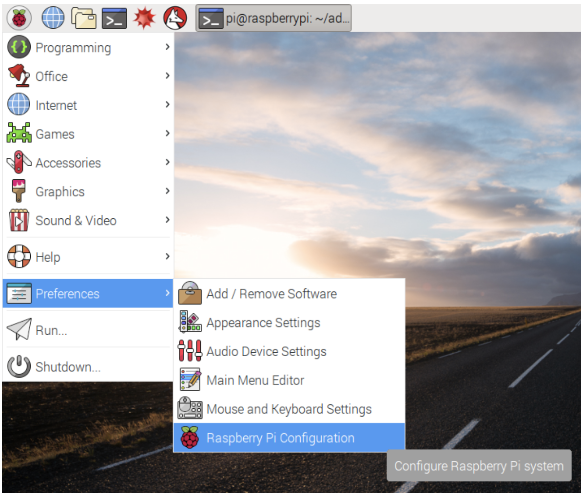
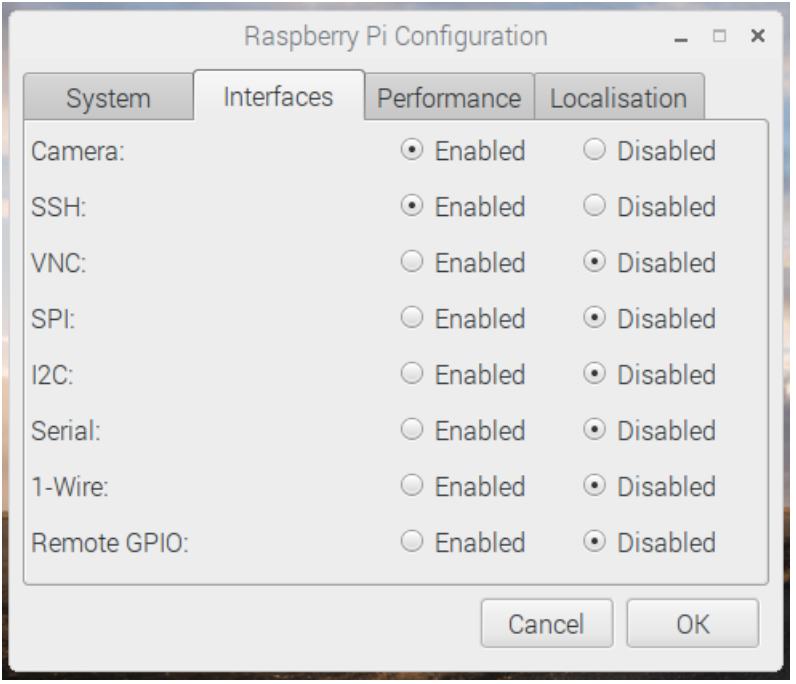
Opening up the Raspberry Pi Configuration tool from the main menu and disable and enable all of the interfaces above
From the Main menu open up the Terminal and type in the following lines of code:
Sudo Raspi-config
Now from here use your arrow keys to operate through the system and click on Peripheral connection option and from their click on P1 Camera and enable the camera, then select finish. Going back to the terminal type in the following lines of code:
pip install picamera
or
Sudo pip install Picamera
Testing the Camera Module
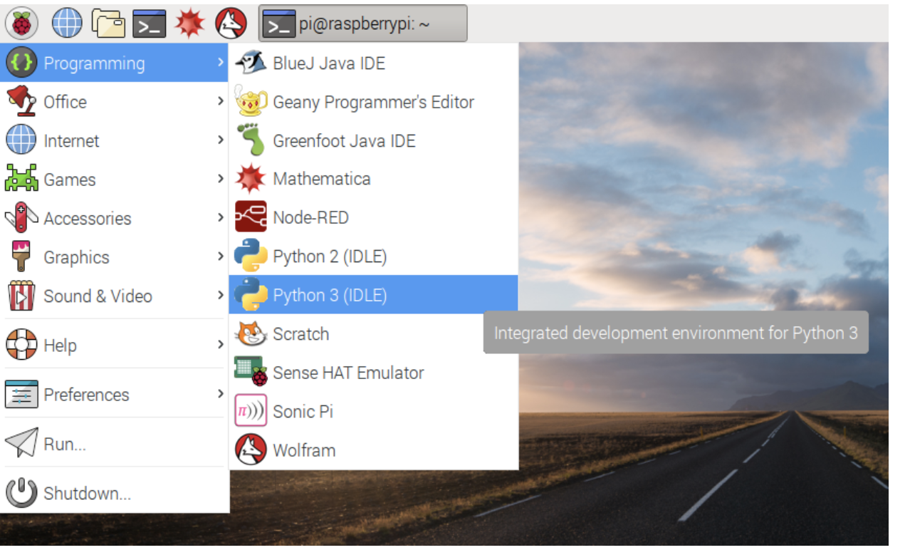
From here we can test if the camera is working or not because we have all of the software and hardware enabled.
- Open Python 3 from the menu
From there open a new file from the shell and save it a cameratest.py.
Enter the following code:
from picamera import PiCamera #imported module created from the pip install pi camera command<br>from time import sleep #imported sleep in order to make sure that our camera stays on

camera = PiCamera() #Setup for the camera
camera.start_preview()#starts up the camera and shows you what the camera output is looking like
sleep(10)#leaves the preview on for 10 seconds
camera.stop_preview()#finally quits the preview
Run the code by F5
If you receive this error when running the code:
(mmal: mmal_vc_component_create: failed to create component 'vc.ril.camera' (1:ENOMEM)
mmal: mmal_component_create_core: could not create component 'vc.ril.camera' (1) Traceback (most recent call last): File "", line 1, in File "/usr/lib/python2.7/dist-packages/picamera/camera.py", line 257, in __init__ self._init_camera() File "/usr/lib/python2.7/dist-packages/picamera/camera.py", line 288, in _init_camera prefix="Failed to create camera component") File "/usr/lib/python2.7/dist-packages/picamera/exc.py", line 112, in mmal_check raise PiCameraMMALError(status, prefix) picamera.exc.PiCameraMMALError: Failed to create camera component: Out of memory)
Please go to the Raspberry Pi configuration go under the performance column and boost your GPU memory until the error is gone (have to reboot).
Now in order to create a photo that will save to the desktop we will use the following code:
<p>from picamera import PiCamera #Imported module created from the pip install pi camera command<br>from time import sleep #Imported sleep in order to make sure that our camera stays on</p><p>camera = PiCamera() #Setup for the camera</p><p>camera.start_preview() #Starts the preview<br>sleep(5)#Leaves the preview on for 5 seconds</p><p>camera.capture('/home/pi/Desktop/image.jpg')# From the
camera.stop_preview()#Stops the Preview</p>
Creating the Circuit With Code!
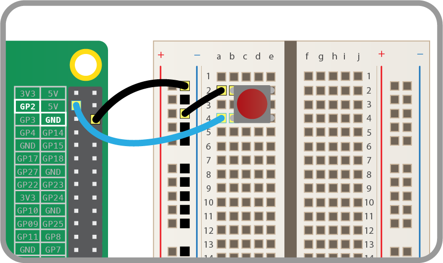
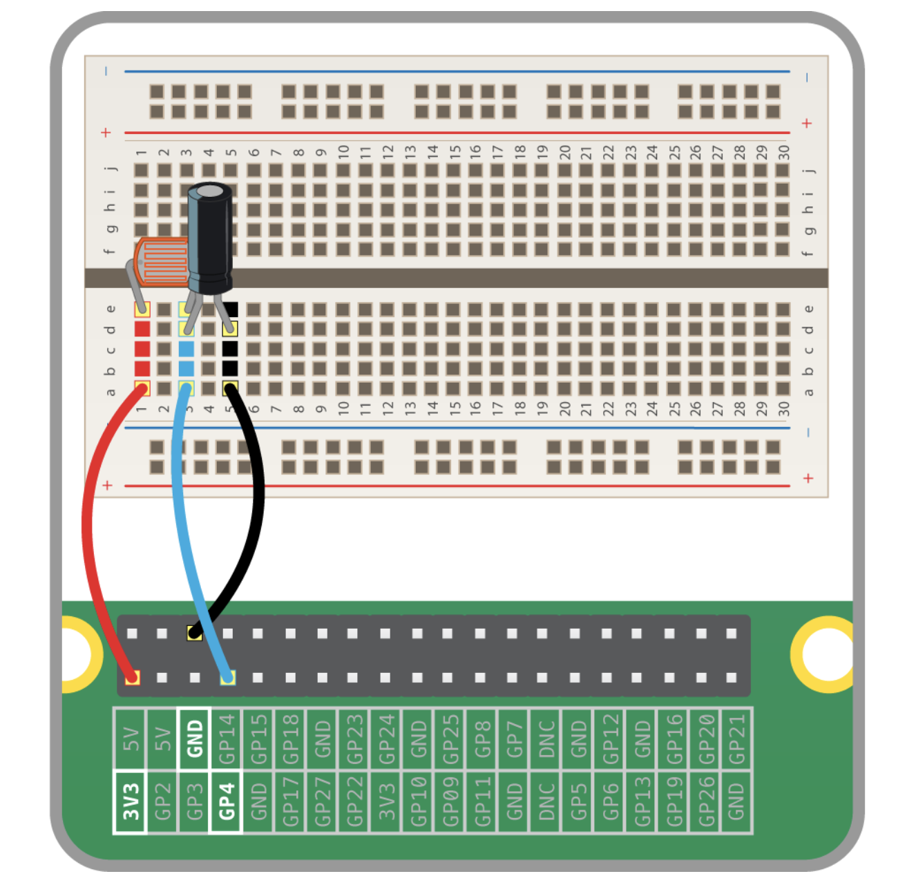
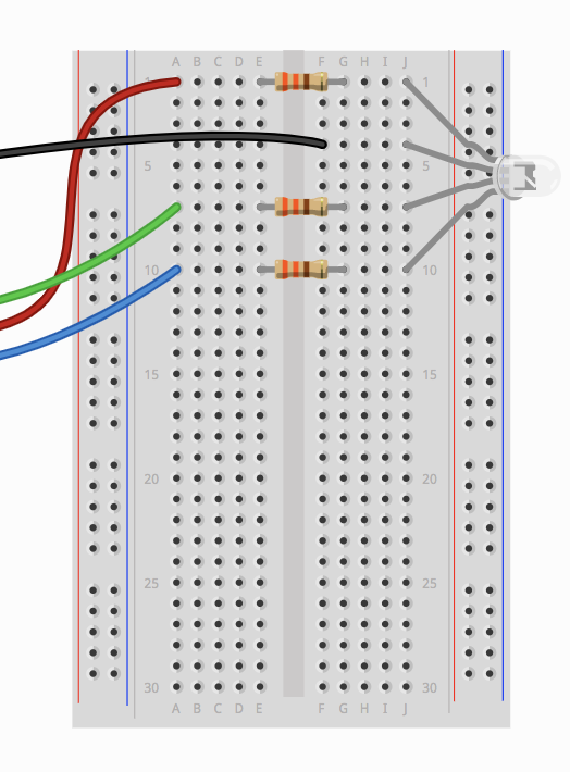
As seen above from the circuit diagrams we need to setup a button, a LDR, and finally two RGB LEDs. First we are going to setup the button on the lower left side of the breadboard. During your setup for the button we will use the common railway lines meaning that we will plug in our 3.3V on the positive and the ground for negative. After you have finished the circuit setup for the button only.
We will test our circuit to see if we can make it so that if the button is pressed we turn the led on using the following code:
<p>#Imported Modules<br>from gpiozero import Button
from picamera import PiCamera
from time import sleep</p><p>#Setup
Camera = PiCamera()
Button = Button(22)</p><p>#Photo taking function, I have decided to put it into a define function as it helps us clean up the main code
def photocap(): </p><p>Camera.start_preview()
sleep(5)
Camera.capture('/home/pi/Desktop/image.jpg')
print ("Photo was taken")
Camera.stop_preview()</p><p>#Main code:
while True:
if Button.is_pressed:
print ("Button was pressed")
photocap()</p><p>

#Why this works: The main code works as all we're doing is using the command if button.is_pressed in a while true statement so it is constantly updating when the button is pressed to take the photo</p>
Now we are going to setup 2 RGB LEDs all the way up to the top of the circuit and separate them at the middle of the breadboard and make the symmetrical. If you do not have 220 ohm resistors for this project you can set them up in parallel depending on your resistance for the resistors you have. The second pin of the 4 pin RGB LED (the longest one should be connected to ground through the railway. The other pins should all be connected to their own GPIO pins. (First pin =red, Second pin = ground, Third Pin = green, Fourth pin = blue).
We will test one of our RGB LEDs in our button circuit with the code below:
<p>#Imported Modules<br>from gpiozero import Button
from picamera import PiCamera </p><p>from gpiozero import RGBLED</p><p>from time import sleep
</p><p>#Setup
Camera = PiCamera()
Button = Button(22)</p><p>TimedLED=RGBLED(red=21,green=20,blue=16)

</p><p>#Photo taking function with RGB LED, I have decided to put it into a define function as it helps us clean up the main code
def photocap():
Camera.start_preview()
sleep(4) </p><p>timedled.color(1, 0, 0)</p><p>sleep(2)</p><p>timedled.color(0, 1, 0)</p><p>sleep(1)
Camera.capture('/home/pi/Desktop/image.jpg')
print ("Photo was taken")
Camera.stop_preview()</p><p style="margin-left: 60px;">#Main code:</p><p style="margin-left: 60px;">while True:</p><p style="margin-left: 60px;">	if Button.is_pressed:
	print ("Button was pressed")
	photocap()</p><p style="margin-left: 60px;">

#Why this works: The reason why this code works is because now we got the RGBLED to work as a timer for when the photo is going to be taken </p>
Now setup the Light Dependant resistor on the lower right side of the breadboard using the diagram all the way up at the top and the common railways discussed before. Remember both of the long legs of the LDR and the capicitator have to be connected to the GPIO pin.
After we have connected the LDR we are going to use the following code:
<p>#Imported Modules</p><p>from gpiozero import Button
from picamera import PiCamera
from gpiozero import RGBLED</p><p>from gpiozero import LightSensor</p><p>
from time import sleep</p><p>#Setup
Camera = PiCamera()
Button = Button(22)
TimedLED=RGBLED(red=21,green=20,blue=16)</p><p>LightSensor=LightSensor(23)</p><p>#Photo taking function with RGB LED, I have decided to put it into a define function as it helps us clean up the main code
def photocap():
Camera.start_preview()
sleep(4)
timedled.color(1, 0, 0)
sleep(2)
timedled.color(0, 1, 0)
sleep(1)
Camera.capture('/home/pi/Desktop/image.jpg')
print ("Photo was taken")
Camera.stop_preview()</p><p>#Main code:</p><p>while True:
	if Button.is_pressed:
	print ("Button was pressed")
	photocap()</p><p>	if Button.is_pressed and Lightsensor.when_dark:</p><p>	print ("Button was Pressed")</p><p>	print("It's dark")</p><p>	photocap()</p><p>

	#Why this works: The way that I have added the Light sensor to my code is through another if statement that contains the imported function of light sensor.when dark setting us up perfectly for our next step</p>
Now the final step through out this project would be to activate the other RGBLED symmetric to the other to work as a flash light,
The final code:
<p>from gpiozero import Button  </p><p>from picamera import PiCamera  </p><p>from gpiozero import RGBLED </p><p>from gpiozero import LightSensor
from time import sleep</p><p> #Setup  </p><p>Camera = PiCamera()  </p><p>Button = Button(22) </p><p>TimedLED=RGBLED(red=21,green=20,blue=16) </p><p>FlashLED=RGBLED(red=19, green=13, blue=6)</p><p>LightSensor=LightSensor(23)</p><p>
#Photo taking function with RGB LED, I have decided to put it into a define function as it helps us clean up the main code  def photocap(): Camera.start_preview() sleep(4)  timedled.color(1, 0, 0) sleep(2) timedled.color(0, 1, 0) sleep(1) Camera.capture('/home/pi/Desktop/image.jpg')  print ("Photo was taken")  Camera.stop_preview()
#Main code:
while True: if Button.is_pressed:</p><p> print ("Button was pressed")</p><p> photocap() </p><p>if Button.is_pressed and Lightsensor.when_dark:
print ("Button was Pressed")
print("It's dark")</p><p>FlashLED.color(1, 1, 1)
photocap()</p><p>

#Why this works: The way that I have added my Flashlight is by using the RGB led to output the color white which is 1,1,1 and it only does theis if the if statement is true.</p>