Raspberry Pi Logic Chip Tester
by ILikePizzas in Circuits > Raspberry Pi
1540 Views, 2 Favorites, 0 Comments
Raspberry Pi Logic Chip Tester

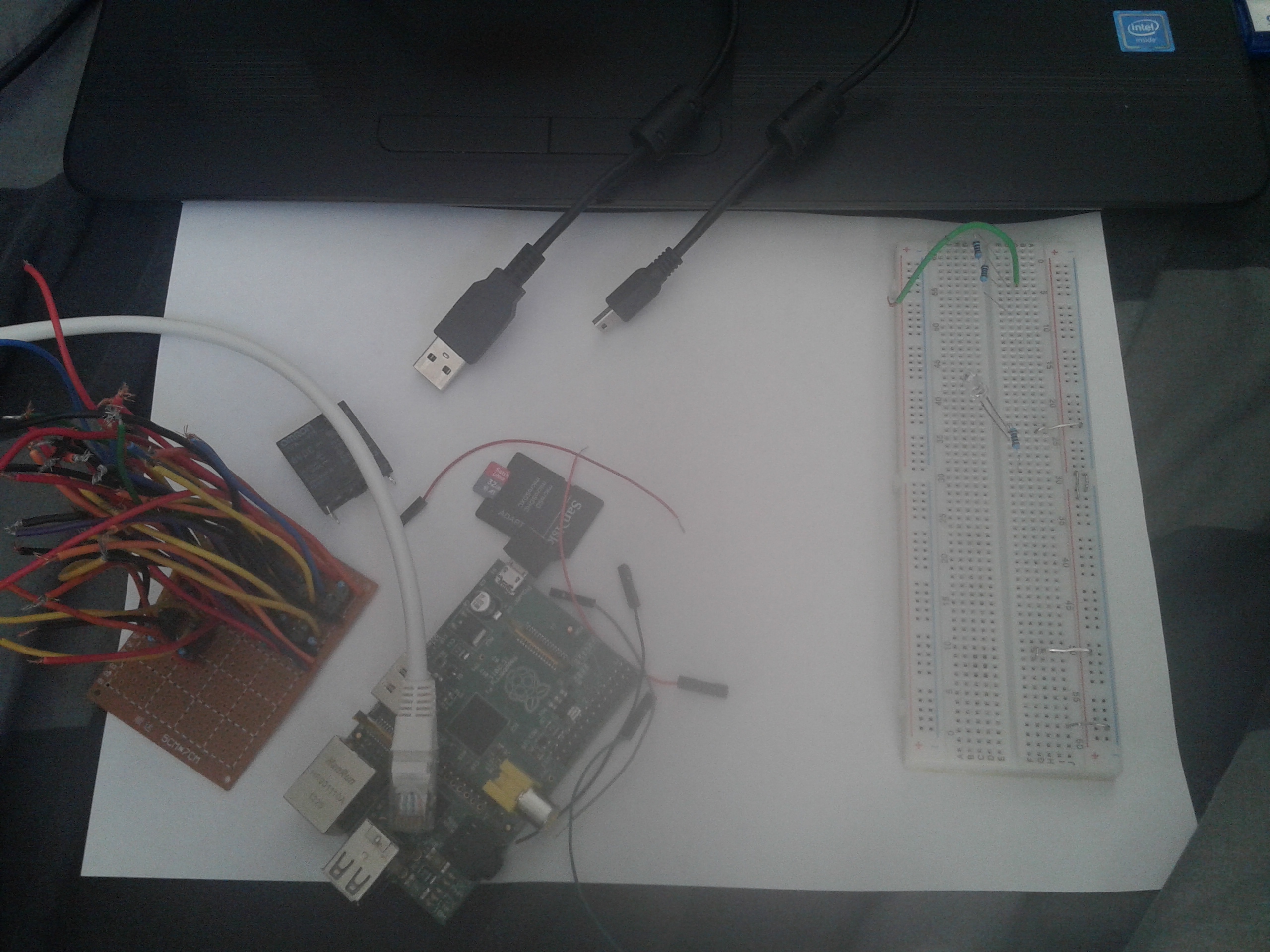
This is a logic tester script for a Raspberry pi, with this you can check if your (self-made) logic circuit works.
This script can also be used to test relays.
WARNING:
The Raspberry pi does not support 5v GPIO inputs, so if your circuit outputs 5V, you will have to get it down to 3V or lower (1.6V seems to work too), you can do this with a simple voltage divider.
Supplies
For this Instructable, you will need:
1 internet cable
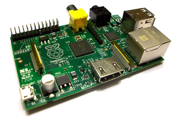
1 Raspberry pi, with SD-card and Raspbian OS.
5 Wires that can connect to the pi's pins
1 breadboard
1 power cable for your Raspberry pi (duh!)
also you will need a computer that has an internet port, and has a terminal program (MobaXterm)
and of course a circuit or component you want to test.
(optional) 1 voltage divider with ratio R1:R2 = 1:1 (i used 2 200 Ohm resistors when needed)
Get the Script on Your Raspberry Pi
Well, if you want to start you will have to have the script, so here it is, you can download it from Google Drive.
With MobaXterm you can drop the file in a place where you want it on your RPi.
if you want to type it in a file manually, there is also a text file that you can copy.
Connecting Your Tester
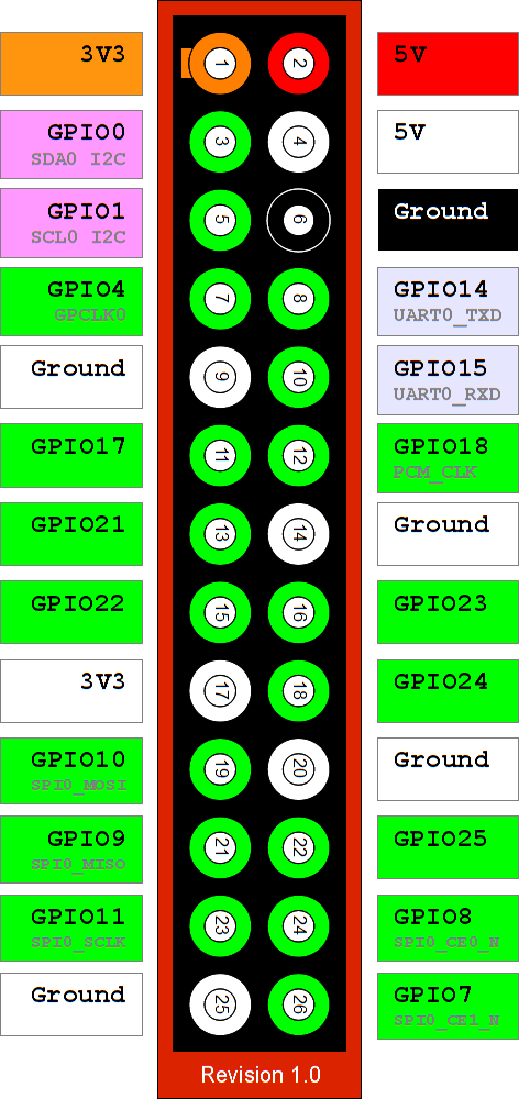
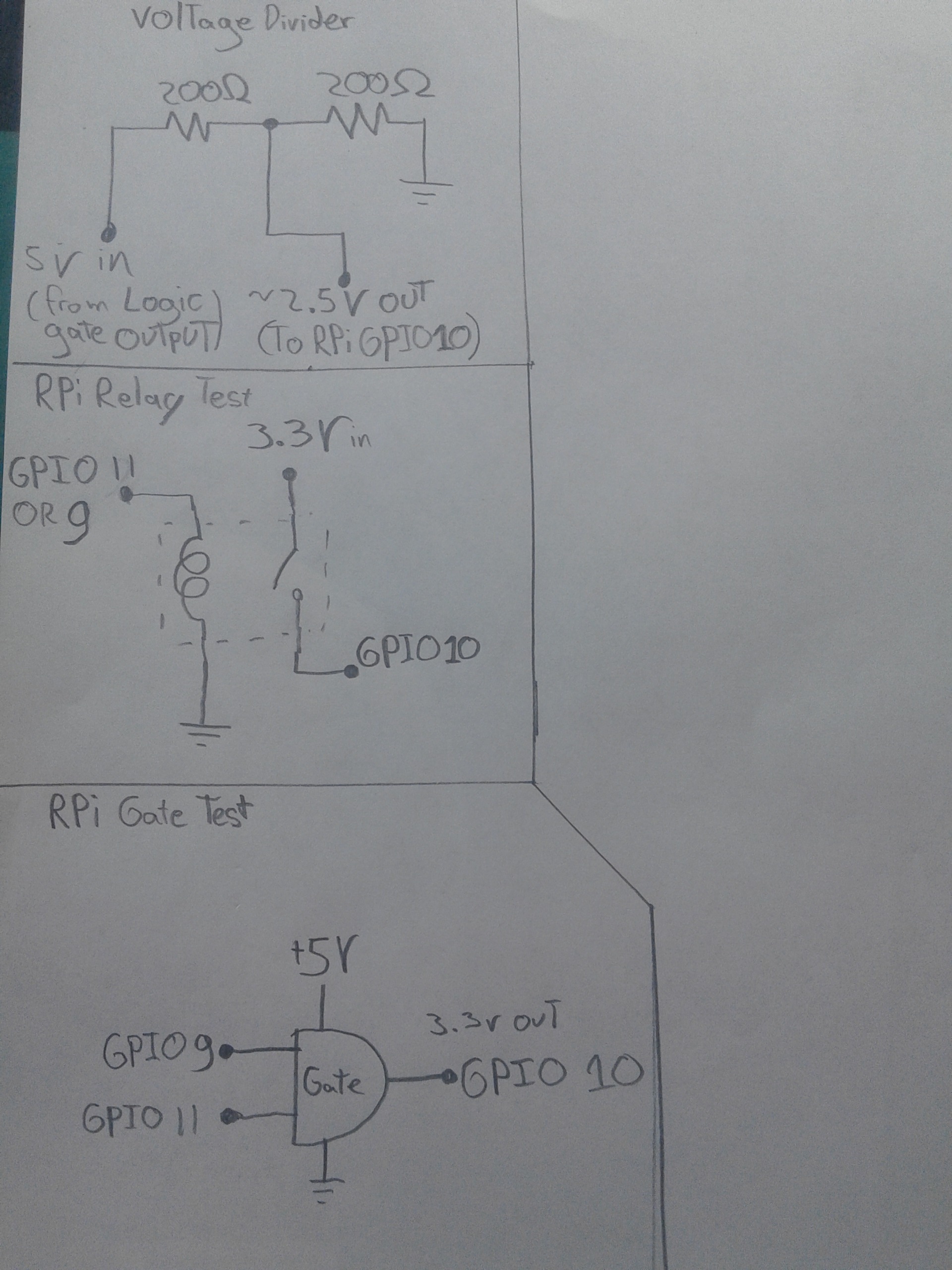
Of course, to get results you would need to connect your tester to the item to test.
Because this is too hard to explain with just text, i have attached two images, one with the RPi pinout, and one with 'wiring diagrams' or something.
On the image you will see a Voltage Divider, which you should use when you are testing 5v output logic gates.
Also there are wiring diagrams for any logic gate (not limited to AND), and for a relay.
I hope these images are good enough to explain to you how to connect everything.
Testing
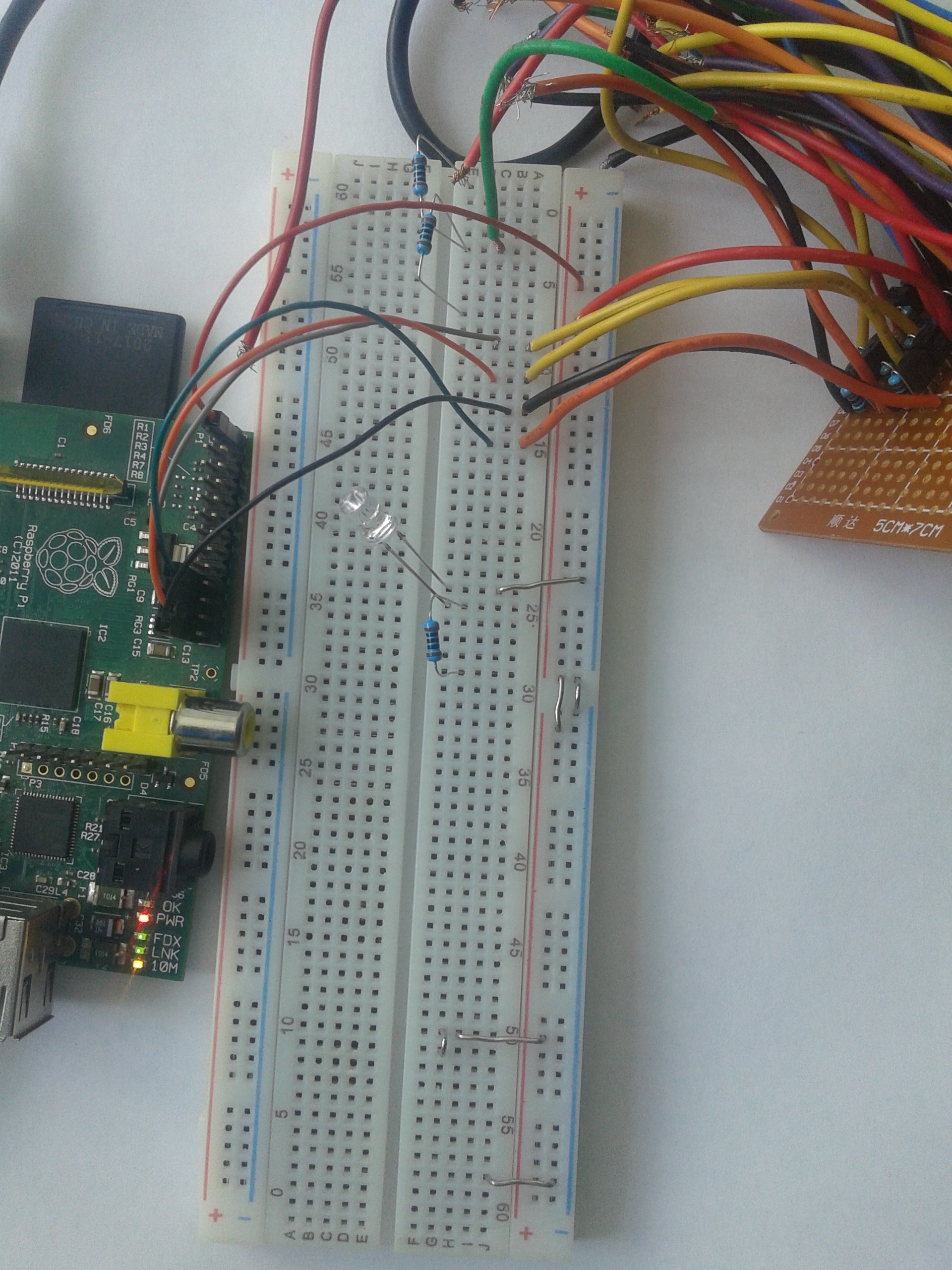
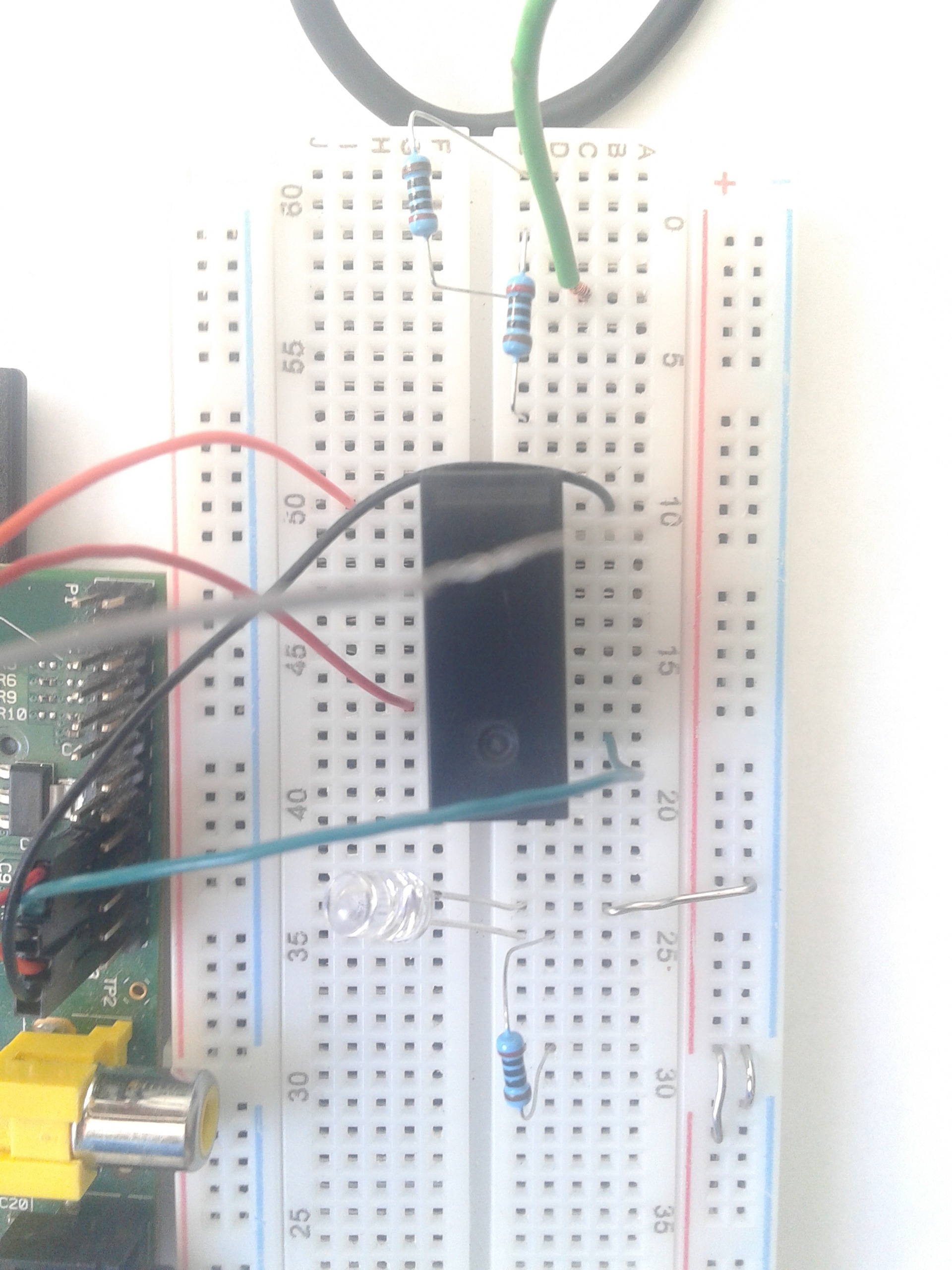
After the completion of step 1 and 2, you can finally test this script, and the tester.
To run the script, go to the directory where the script is located,
and then run it by typing: python3 LOGIC_TESTER.py
(you do all of this in your Raspberry pi's terminal)
after typing the code shown above, you will just have to type the numbers 1 or 2, and hit enter, depending on what you want the script to do.
Results


Congratulations: you now have your first results from the tester, above are some examples of results
The tester first runs a series of inputs through the logic gate/relay, and then saves the output, later it will compare the outputs to the truth tables of all existing logic gates.
If the outputs are the same as a certain logic gates, it will output the name of the gate you were testing.
if the outputs are not equal to any of the truth tables, your logic gate is likely broken, or the connections are bad.
have fun using the tester, and i hope you find this Instructable helpful.