Raspberry Pi Hi-Fi Audio Streamer With Touchscreen Control and Max2Play
by Max2Play in Circuits > Raspberry Pi
6039 Views, 13 Favorites, 0 Comments
Raspberry Pi Hi-Fi Audio Streamer With Touchscreen Control and Max2Play
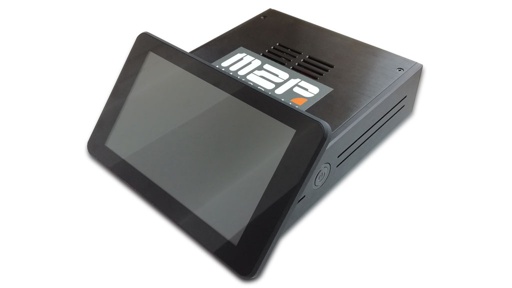
Here, we will detail the assembly of the new Raspberry Pi Touch Streamer. The corresponding bundle with all necessary components for this setup can be found in the Max2Play shop. If you already own these parts, the case can also be bought separately. Please adhere to these instructions to prevent damage to the devices. This manual explains step by step the assembly of the Streamer Kit. You can visit our Blog for more information on the topic.
Components
We offer a bundle including all necessary components for this instructable in our shop.
General components:
- Raspberry Pi 3
- RaspTouch Case
- 7" Touch-Display
- Power Management Module
- 7-12V Power Supply
- Sound Card with additional GPIO bar
- Class 10 MicroSD card with preinstalled Max2Play Image
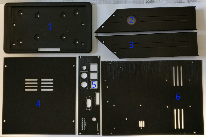
The case consists of the following parts:
1. case front panel (7 inch Display holder)
2. right side panel
3. left side panel
4. case top
5. case back panel
6. case bottom
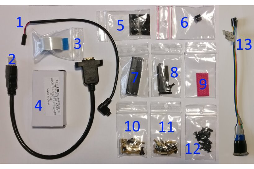
The bundle also contains:
1. Micro-USB adapter or Jumper cable
2. HDMI port
3. display cable
4. SD card port
5. 4 rubber feet
6. sealing nipple
7. mounting material for the display holder
8. mounting for SD card port (2 larger, 2 smaller screws) and connector
9. rubber isolation piece
10. Package with mounting material for the Raspberry Pi (6 nuts, 6 spacers, 6 small screws, 2 slightly larger screws, an insulation piece, a plastic ring)
11. Package with mounting material for the display board (4 spacers, 4 nuts, 4 screws)
12. 22 M3 (4mm – PH2 compatible) and 4 silver screws for the case
13. Power Button with pre-mounted cables
Assemble the Case 1/2
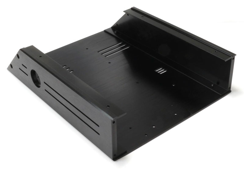
The first step entails affixing the lateral plates with the bottom plate. Take the necessary plates (side and bottom plates) and 4 of the M3 (4mm) screws from the package with the screws for the case. Make sure that the bottom plate is installed correctly. Picture 1 serves as an orientation.
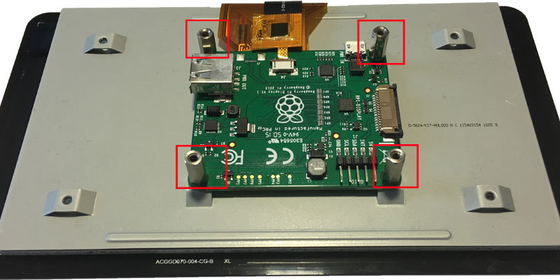
You need to remove the board of the 7 inch touch display. To do so, first remove the spacers and then loosen the board. The original spacers of the display are not part of the further assembly. They are replaced by golden spacers from the delivery scope, when the board is installed in the case.
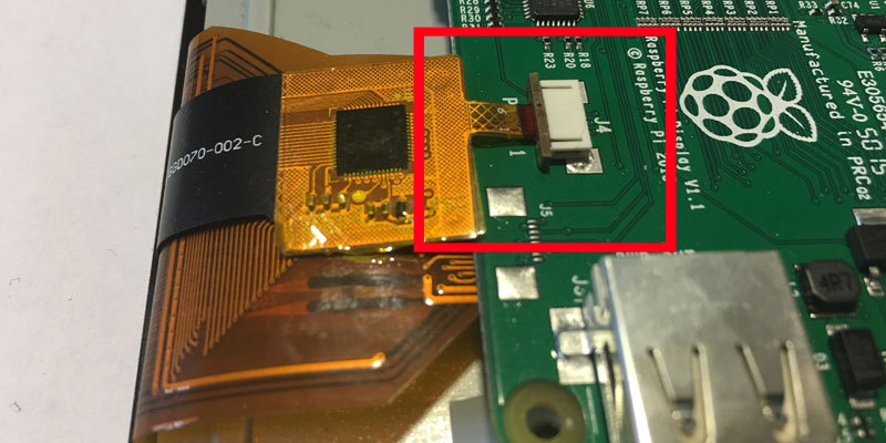
Be careful while removing the display board. It is connected to 2 flat ribbon cables. Loosen the cables, so the board can be carefully removed from the actual display. To remove the cable, a locking mechanism (see marking in picture 3) must be released first.
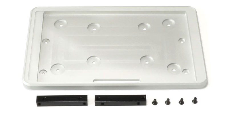
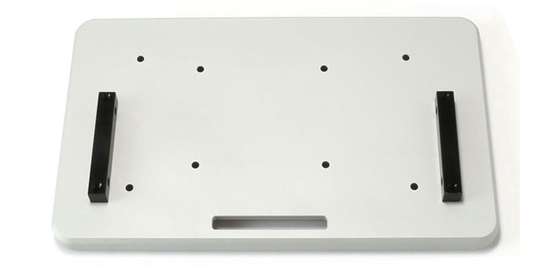
Now the display mount needs to be assembled. Therefore, you need the mounting material for the display holder and 4 of the M3 (4mm) screws for the case. Use the 4 screws to mount the 2 black bars with the display bracket.
Assemble the Case 2/2
Use the display bracket and feed the flat ribbon cable from the front though the recess. Then place the touch display. Fix the display with four M3 (4mm) screws. Then both flat ribbon cables can be connected with the board of the display again.
Note: The display board will not be fixed to the display backside, but to the case of the RaspTouch itself. This will be done in a later step. The delivered Jumper cables have to be connected to the corresponding connectors at the display board (pins "5V" and "GND"). The display cable from the delivery scope has to be affixed to the side of the plate. The other end of the cable will be connected to the Raspberry Pi later.
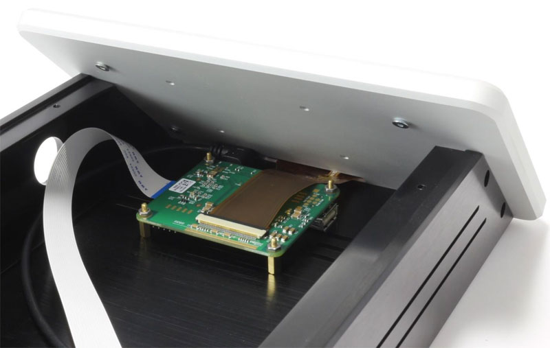
Now the display board can be attached to the bottom plate. You need four M2.5 (13mm) spacers (gold-plated), four of the bigger nuts and four of the M2.5 (4mm) screws from the package with the mounting material for the display board.
Add the spacers to the display board and fix them with the nuts. Now you can feed the screws from the outside through the bottom plate into the case and fix the display board to the floor plate.
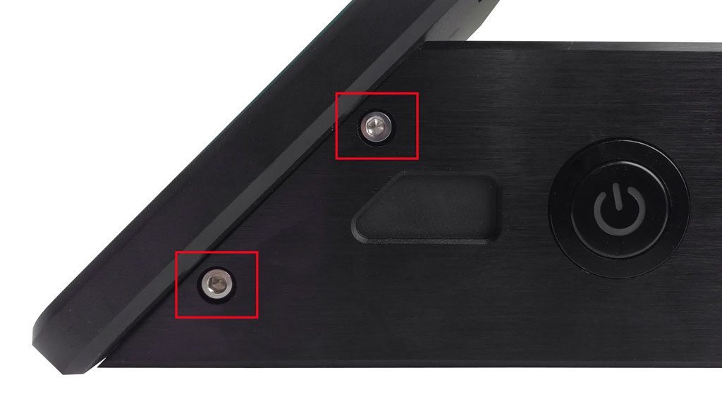
Now the 4 silver case screws will be used to combine the display bracket with the frame (floor and lateral plate).
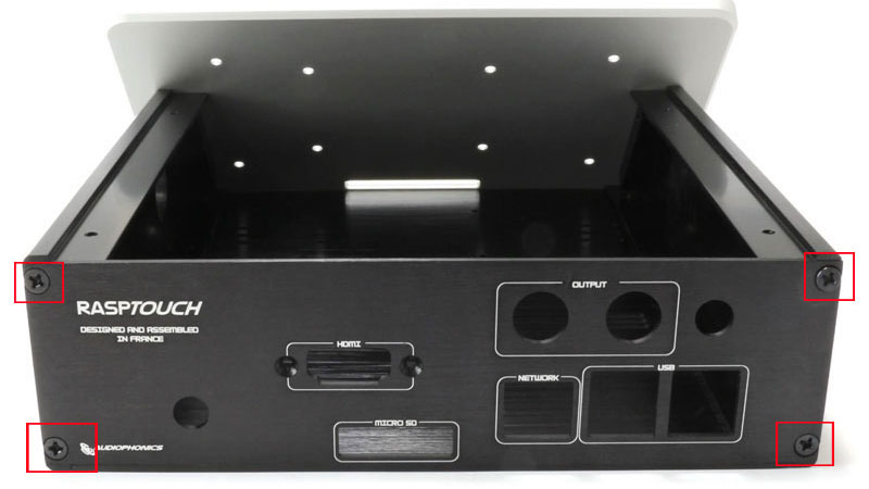
Take the back panel with the different recessed parts and 4 M3 (4mm) screws. The back panel can now be assembled. Use pictures 3 and 4 for further help.
Inserting the Power Management Module
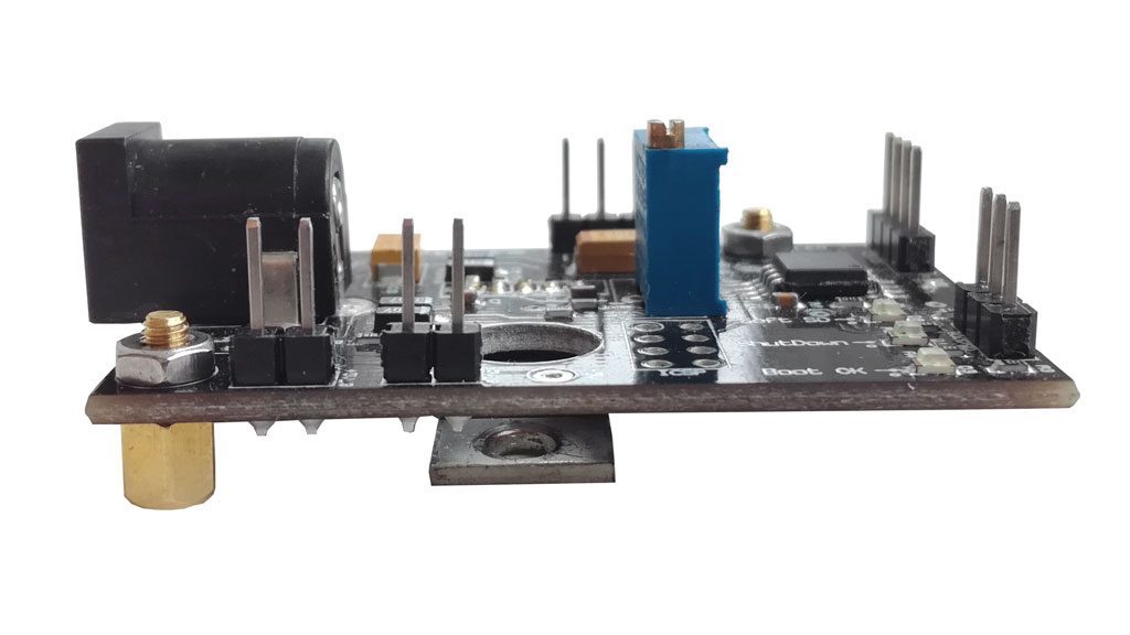
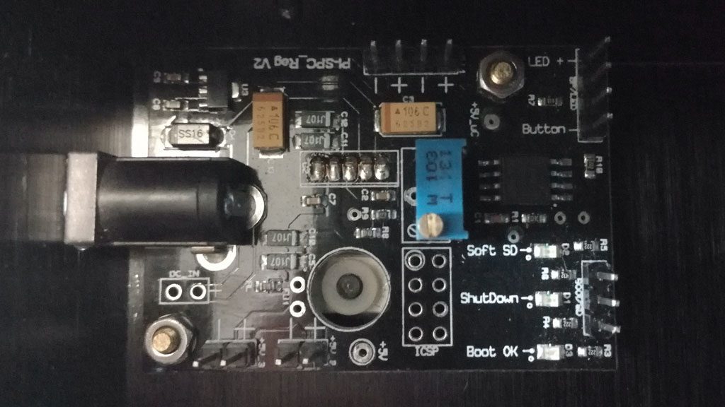
Next, screw the power management module into the back right corner of the case. Use two of the small black and one of the two slightly larger body screws, as well as the plastic ring of packet 10 and two of the smaller spacer screws and nuts. Take the pictures for reference.
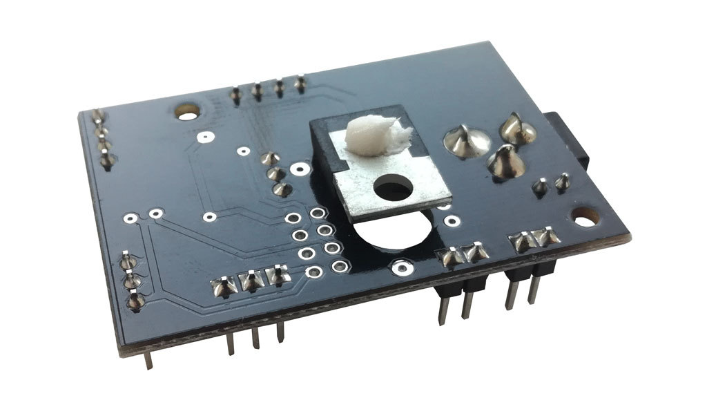
In order to ensure a correct heat dissipation and thus counteract an overheating of the circuits, we recommend the use of a heat sink or thermal paste on the module. This is particularly true with high voltage input (12V). A small tube of thermal paste is already included in the bundle, which you can attach between module and case.
Installing the Ports
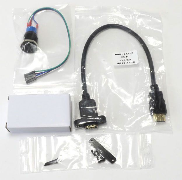
You'll need the following for the next step:
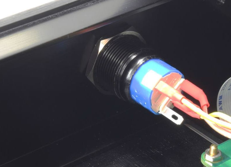
- Power Button with presoldered cables
- HDMI port
- SD card port
- fixture for SD card port (metal plate with 2 holes and the two long screws)
- mounting material for the HDMI port (the two long black screws and the two small nuts from the package with the mounting material for the display board)
First the SD card port is attached. Simply feed the end of the SD card port through to the matching recess on the backside. The SD card port is assembled with the delivered retaining plate. The attachment will be done within the case and onto the SD card connectors. Both M1.5 (12mm) (round head) screws will then be screwed through the bottom of the floor plate into the recessed part.
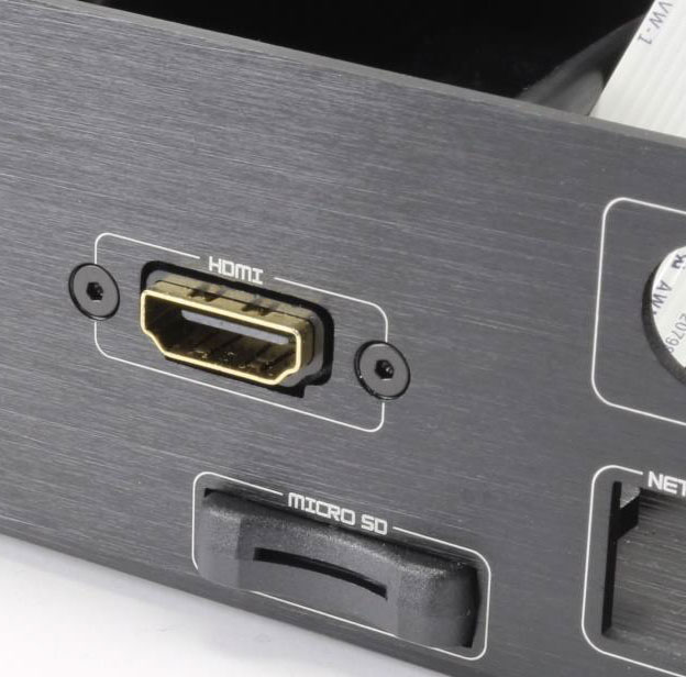
Now mount the HDMI port as follows:
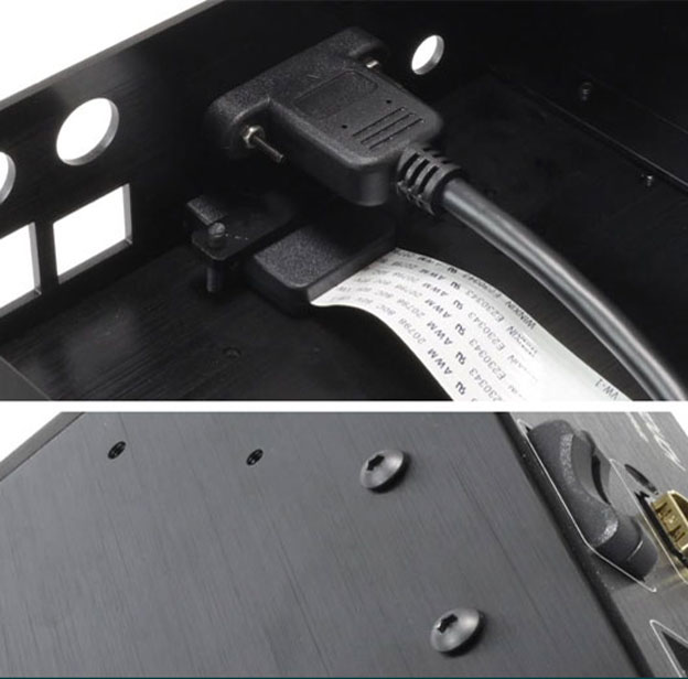
Feed the end of the HDMI port through to the matching recess on the backside and fix the HDMI port to the case with the two long M2 (16mm) countersunk head screws and the two nuts. The screws will be applied from the outside of the case and the rubber-end of the HDMI connector and fastened with the two nuts from the inside.
To use the power button the nut needs to be removed. Then the power button can be fitted into the front plate hole. Use the nut to position the button correctly. See pictures 4 and 5 for comparison.
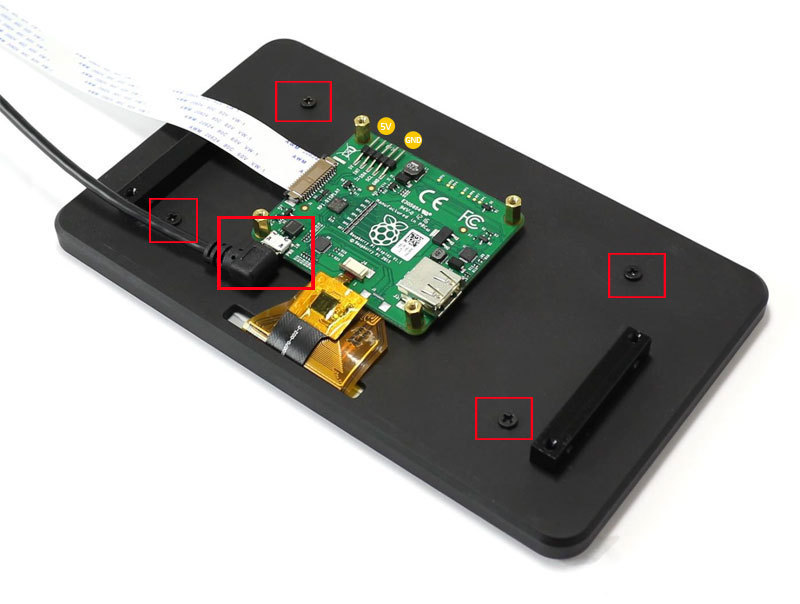
Installing the Sound Card
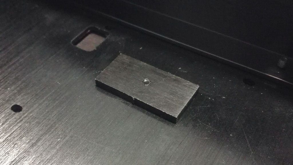
First the heat conduction paste needs to be applied on the case. Simply mount the supplied metal plate with the screw from the delivery scope number 8 to the spot where the Raspberry Pi will later be connected. The screw is then inserted from below through the corresponding hole in the bottom plate of the case and screwed into the metal plate. Then place the heat conduction paste on it.
Note: To find the right spot of the metal plate, the image should serve as orientation. A corresponding hole can be found in the bottom plate. Alternatively, shortly place the Raspberry Pi with the connectors on the corresponding recesses on the back panel. The plate with the heat conduction paste should be applied below the processor of the Raspberry Pi.
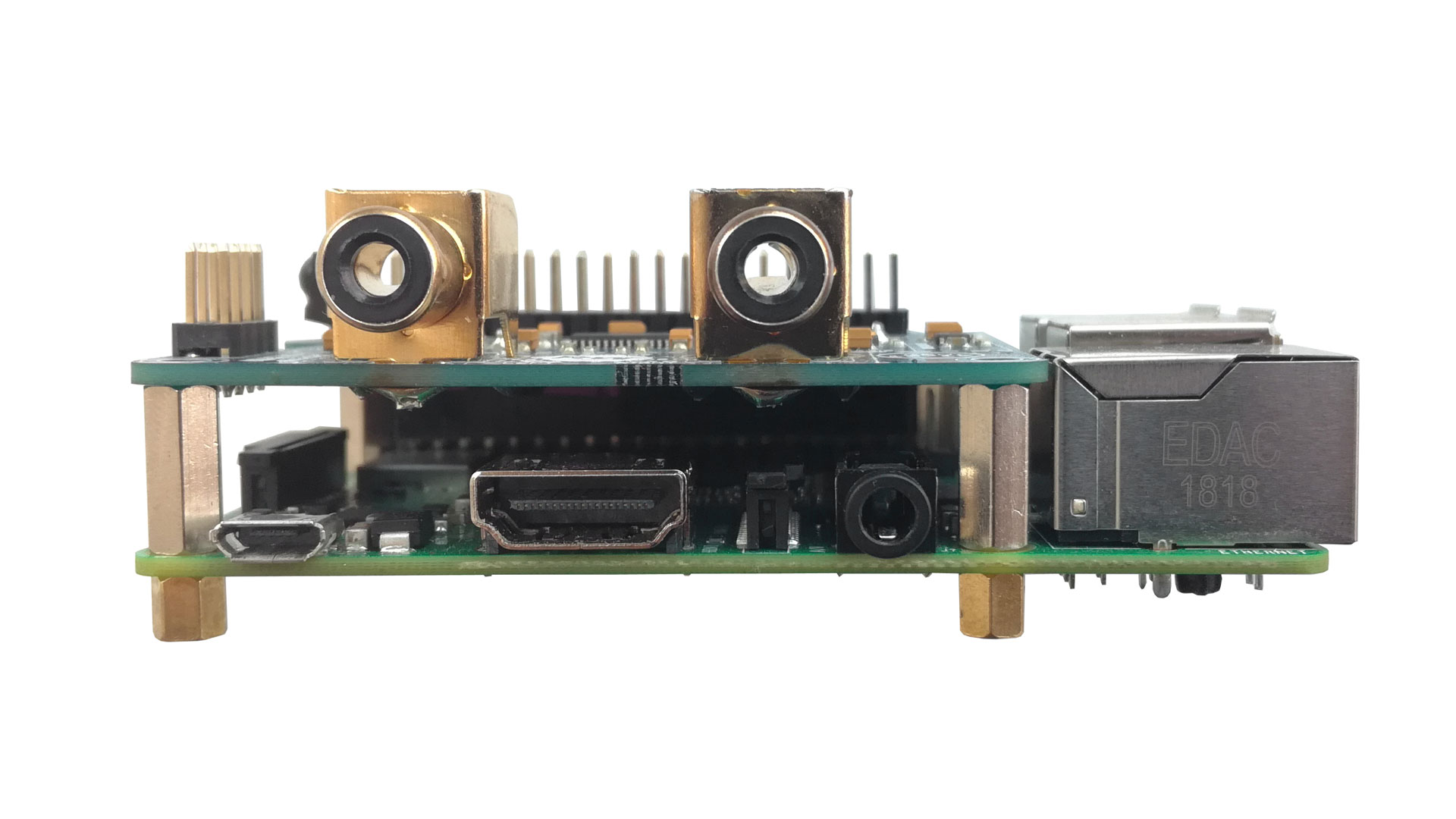
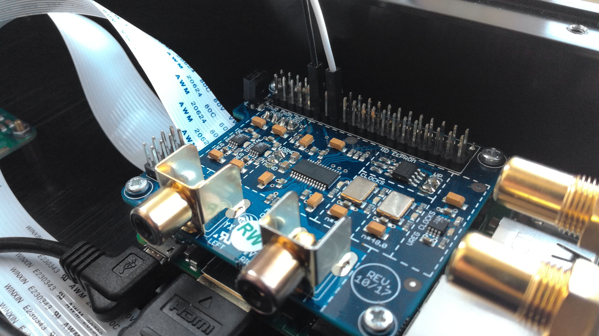
Now the sound card (in this example the AroioDAC) is attached to the Raspberry Pi. The required parts are included in the package of mounting material for sound card and the Raspberry Pi. First, the short spacer screws are inserted through the 4 holes of the Raspberry Pi from below. From above, the long spacers are now screwed onto them. Now the sound card can be plugged onto the Raspberry Pi and fixed with the appropriate screws from above.
Connect Everything
Stick the connection cable of the display to the provided port and fix it there. The blue side of the cable should point to the outside of the board. The Micro SD extension should snap into the bottom of the board (see picture 1).
With 4 of the small black case screws, the Raspberry Pi is fixed to the bottom of the case. If the drill holes in the case do not close with the spacer screws on the bottom of the Pi, we recommend using not all, but at least 2 screws.
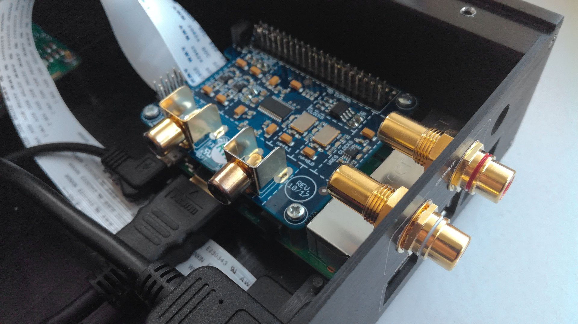
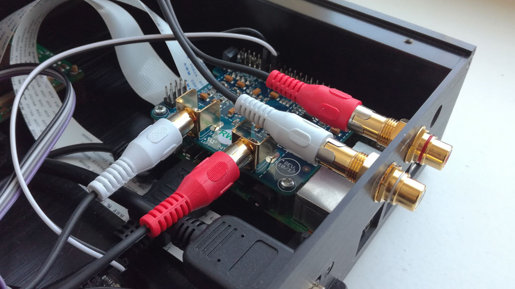
Note: As already mentioned, the heat conduction paste should be applied below the processor of the Raspberry Pi! You can now also attach the two golden RCA adapters to the case as shown in the picture. Use the nut for fixation.
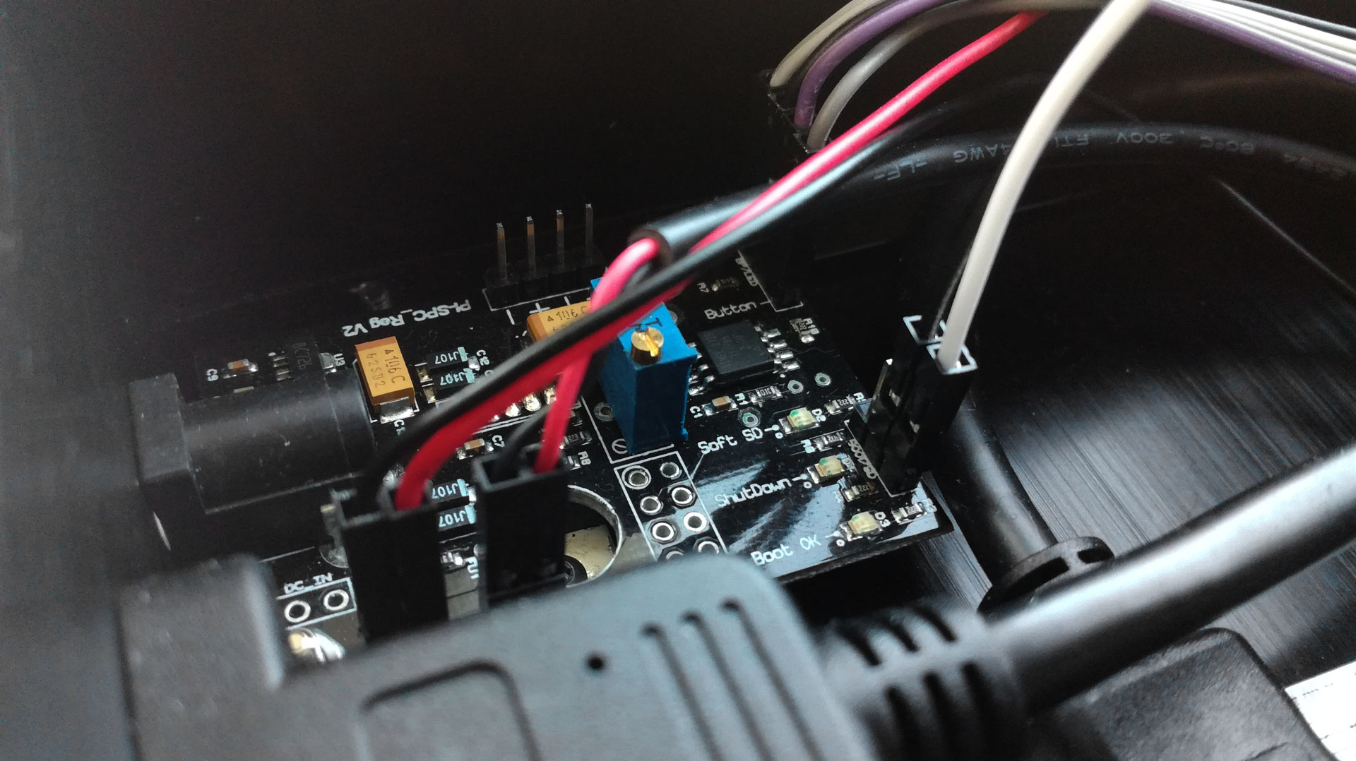
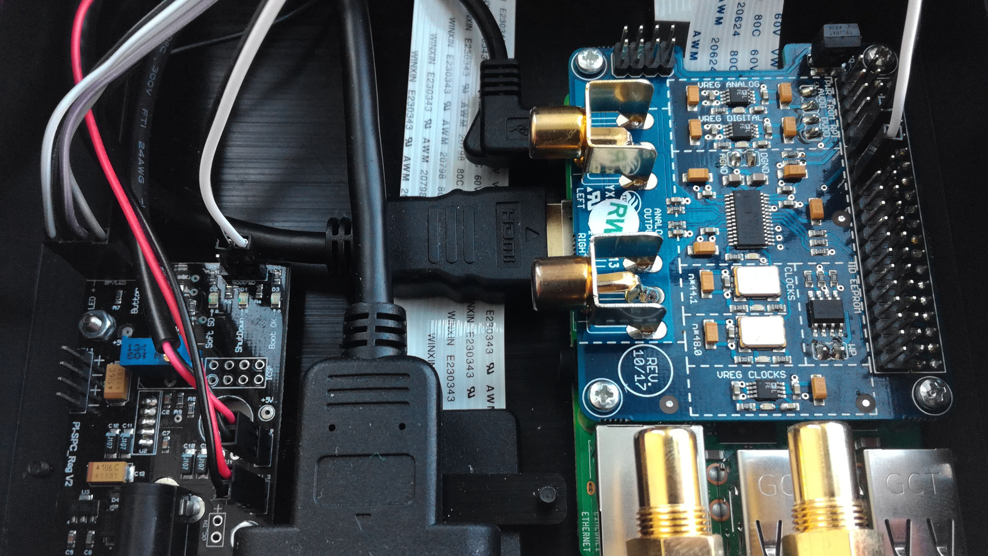
Now the jumper cables of the display board and the power button are connected to the power management module.The USB cable to power the Pi and the jumper cable for clean startup and shutdown are now required (GPIO17 and 22). Also missing is the RCA cable to connect the adapter on the case with the ports of the sound card.
When connecting, follow the pictures in the next step.
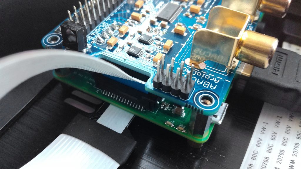
How to Connect the PMM to Different Sound Cards
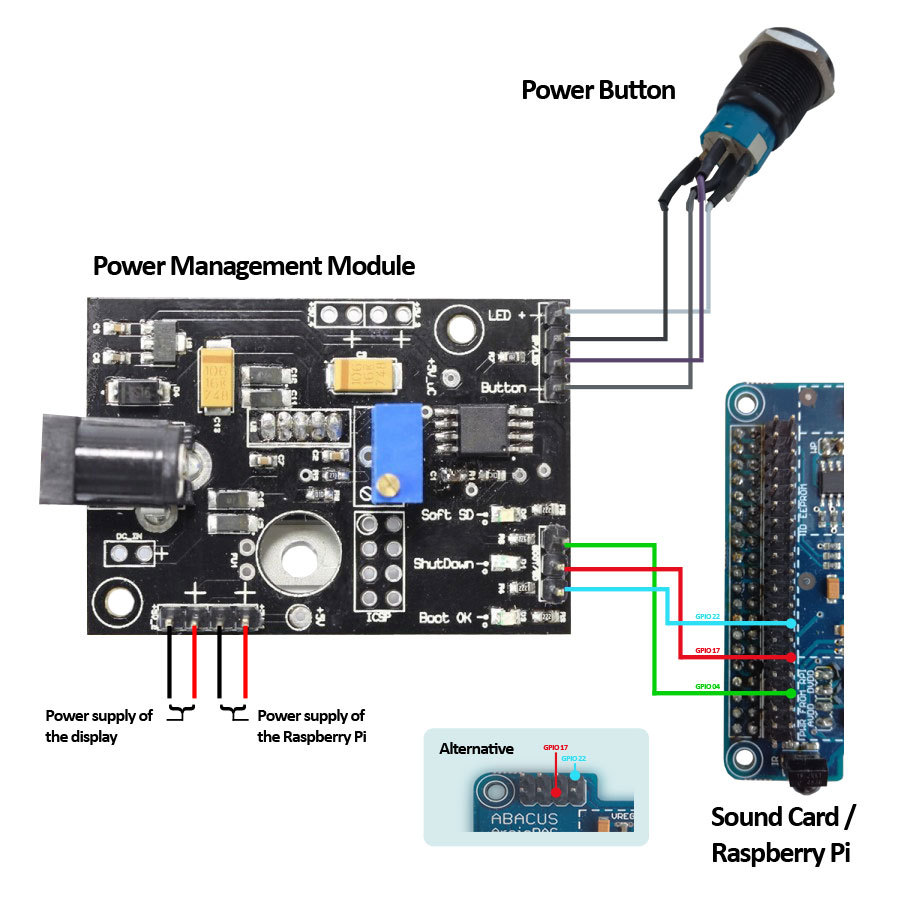
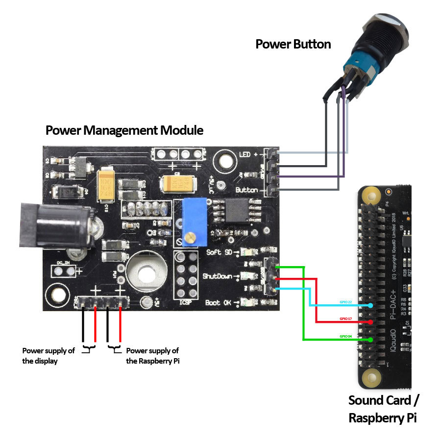
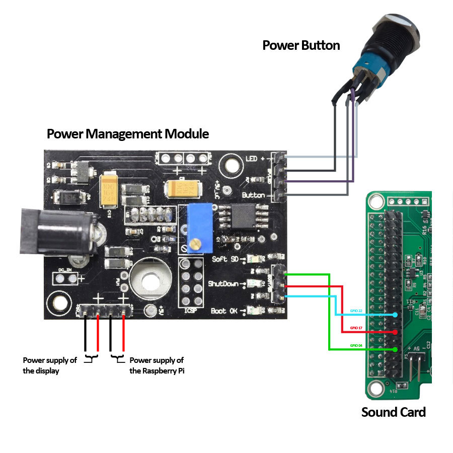
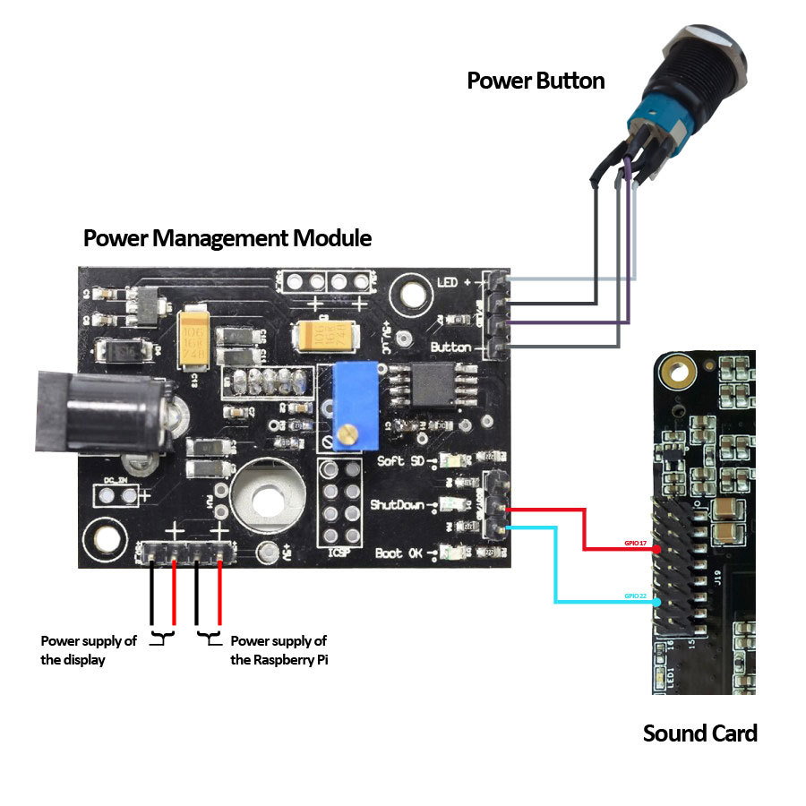
Note: To use the boot and shutdown feature of the power button, the sound card must provide GPIOs 17 and 22 for free use. Some cards, such as the Allo BOSS DAC or the AroioDAC, have already soldered pins for using the GPIOs. For cards where this is not the case (such as the HiFiBerry DAC +), the corresponding pins must be soldered by oneself.
Please make sure that the GPIO17 and GPIO22 for sound cards which are not listed here are not in use.
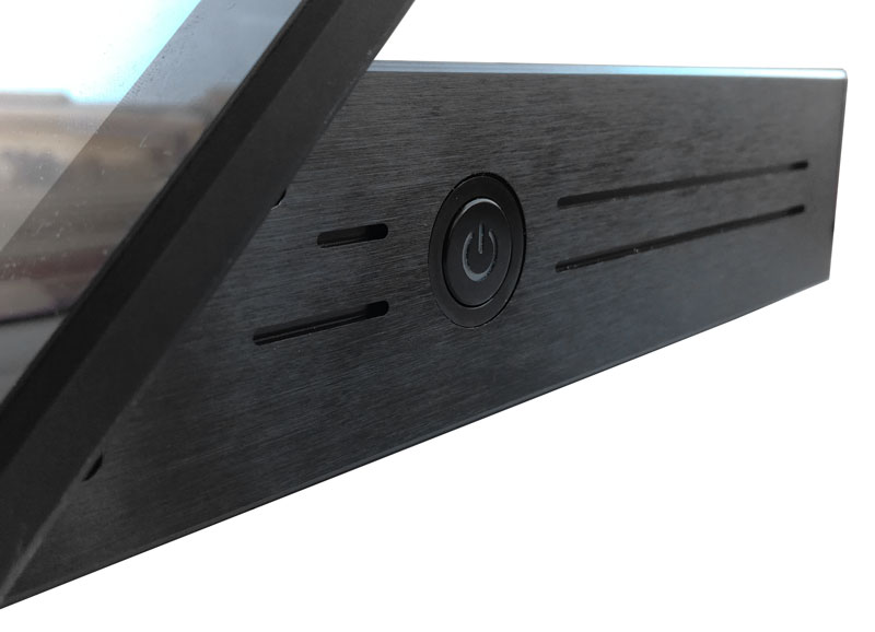
Enjoy Your New, Elegant Touchscreen Panel With Amazing Sound and Simple Controls
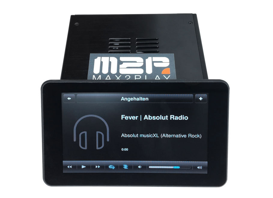
Finally the cover plate can be fixed on top. Use the remaining 4 M3 (4mm) case screws and the top plate. Slide the plate carefully over the case. Now the plate can be fixed.
Then the SD card (optionally with Max2Play preinstalled) can be plugged into the designated port. Connect the device with the power supply and push the power button. The system now boots and the touch screen and Max2Play are ready to be used.
After the start of Max2Play, the power button has to be installed in the Audiophonics plugin, so that the whole system can be turned on and shut down with the button in the future.
Just click on the installation button for the „Power Button“ in the advanced settings in the Audiophonics Plugin and set a checkmark for Autostart. After a restart the button is ready for use.
You can find more information about this bundle in our Blog.
We hope you enjoy this new sound solution by Max2Play and we would love to hear your feedback, here in the comments and on our Forums and Facebook page.