Raspberry Pi Garage Door Opener
by mrbigbusiness in Circuits > Raspberry Pi
1117 Views, 8 Favorites, 0 Comments
Raspberry Pi Garage Door Opener
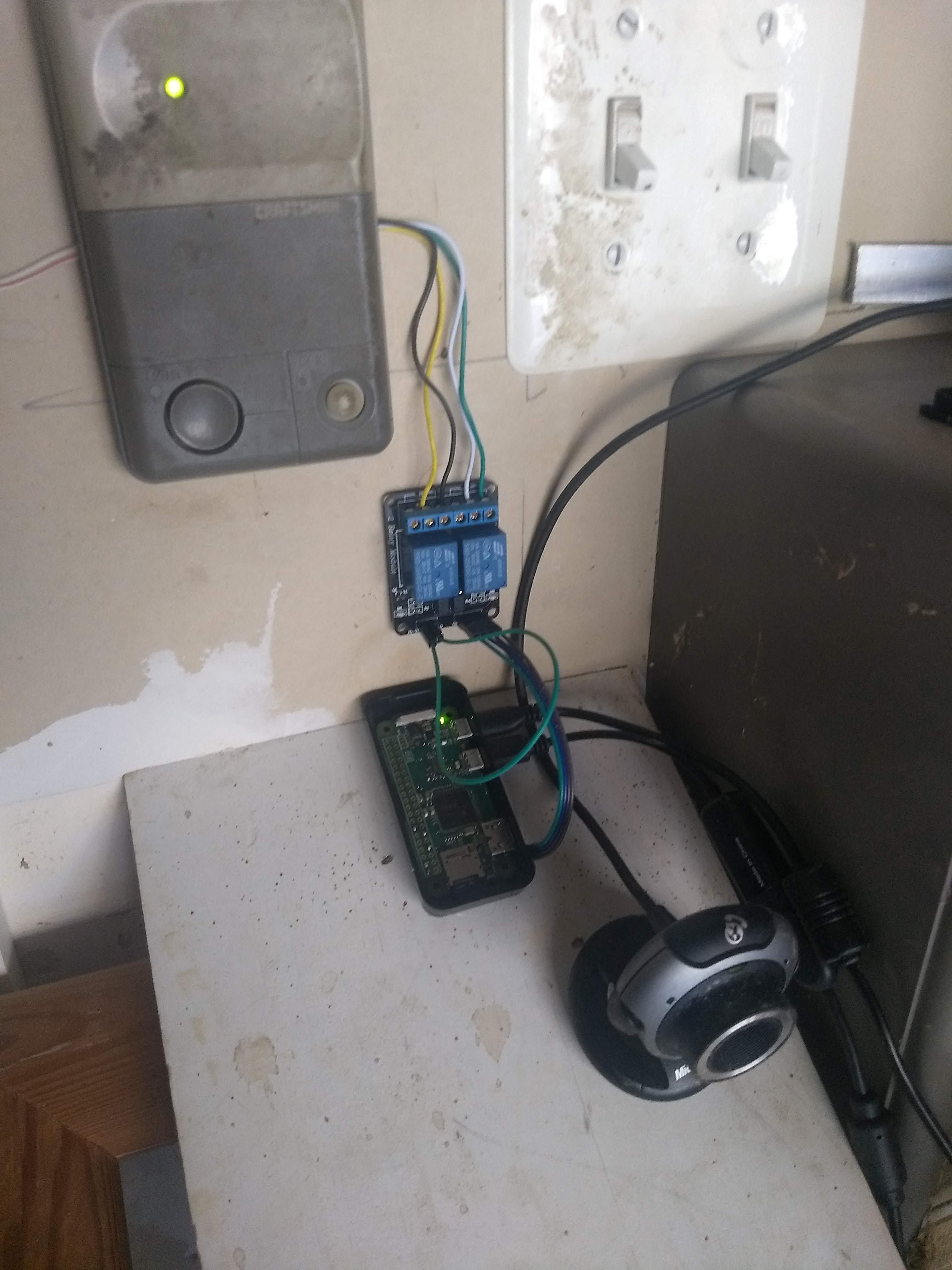
Our Fifteen year old keypad that allows us to open the garage door has been slowly dying, with several buttons that barely register, making it difficult for our teens (or dogsitter) to get into the house when they forget their key.
Instead of replacing it, and jumping through the hoops of reprogramming it, I decided to go a little more high tech and replace it with something that only required access to our wifi and a phone to use.
I used a Pi Zero Wireless and a 2-channel relay that I had left over from another project, which allows me to control both the door and the lights that are built into the garage door opener. Because I had an old/spare USB camera laying around gathering dust, I used that instead of a PiCam, but that was only out of convenience. This would work just fine with any supported camera - there's nothing special about mine, just that Raspbian supported it.
Unlike some other similar projects, I tried to keep it as simple as possible, using "standard" software packages that are pretty easy to get up and running if you follow along with the instructions. This photo shows my final (not pretty at all, but it's my garage) installation, including the Pi, the Relay Module, and USB Webcam pointed at the door. There's no specific reason for using the Pi Zero - any Pi would do, as long as you can get it connected to your internal network, and wifi makes that easy.
Connecting to the Existing Control Panel
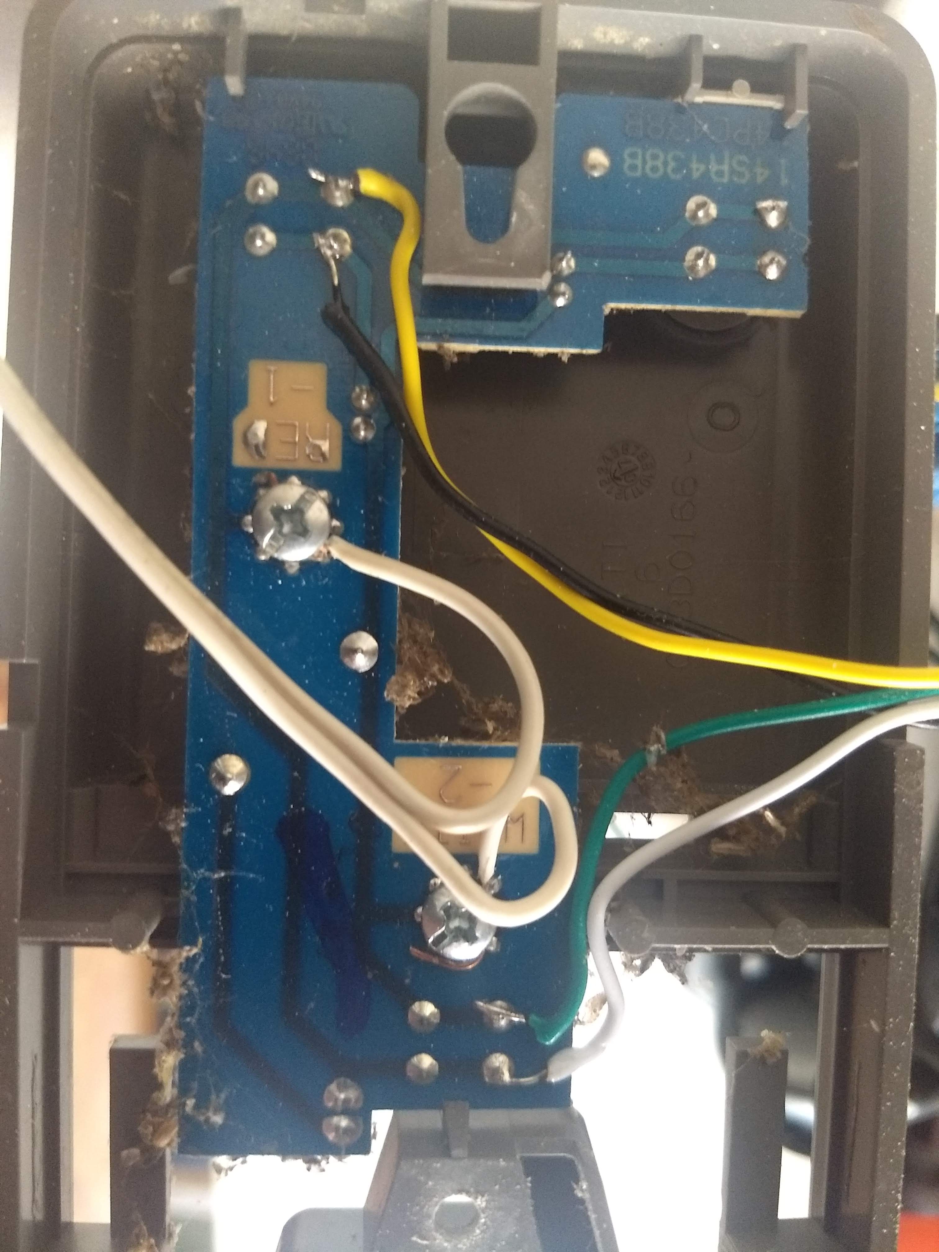
First, YOURS MAY BE DIFFERENT! Mine has a single pair of wires going from the garage door opener to the control panel on the wall. Since there's only two wires, which seemed to have about 18volts when tested, I was a little confused at first about how exactly this thing can control multiple functions. I THINK that each momentary button simply completes the circuit, but with different levels of resistance. Then the main unit can read that resistance via different voltage drops and perform the correct action. None of this matters, though, unless you are trying to completely replace the control unit with the Pi. Not sure why you'd want to do that, since it's nice to still have the physical unit in place.
AAAAAnnnyway, all you need to do is replicate the various button pushes by connecting the momentary switches on the PCB to your relay module. This was the only soldering I had to do, and the pads on the PCB were pretty big, so it was pretty simple. Leave these wires kind of long for now, since it's much easier to shorten a wire than to lengthen it later, unless you have an ACME wire stretcher laying around, but those are pretty rare.
Wiring Up the Relay Board
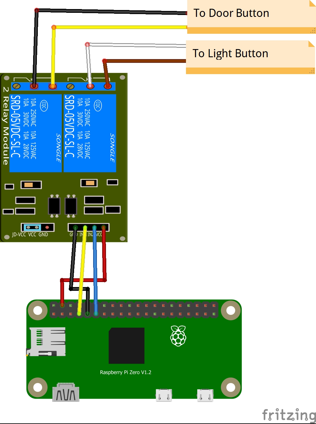
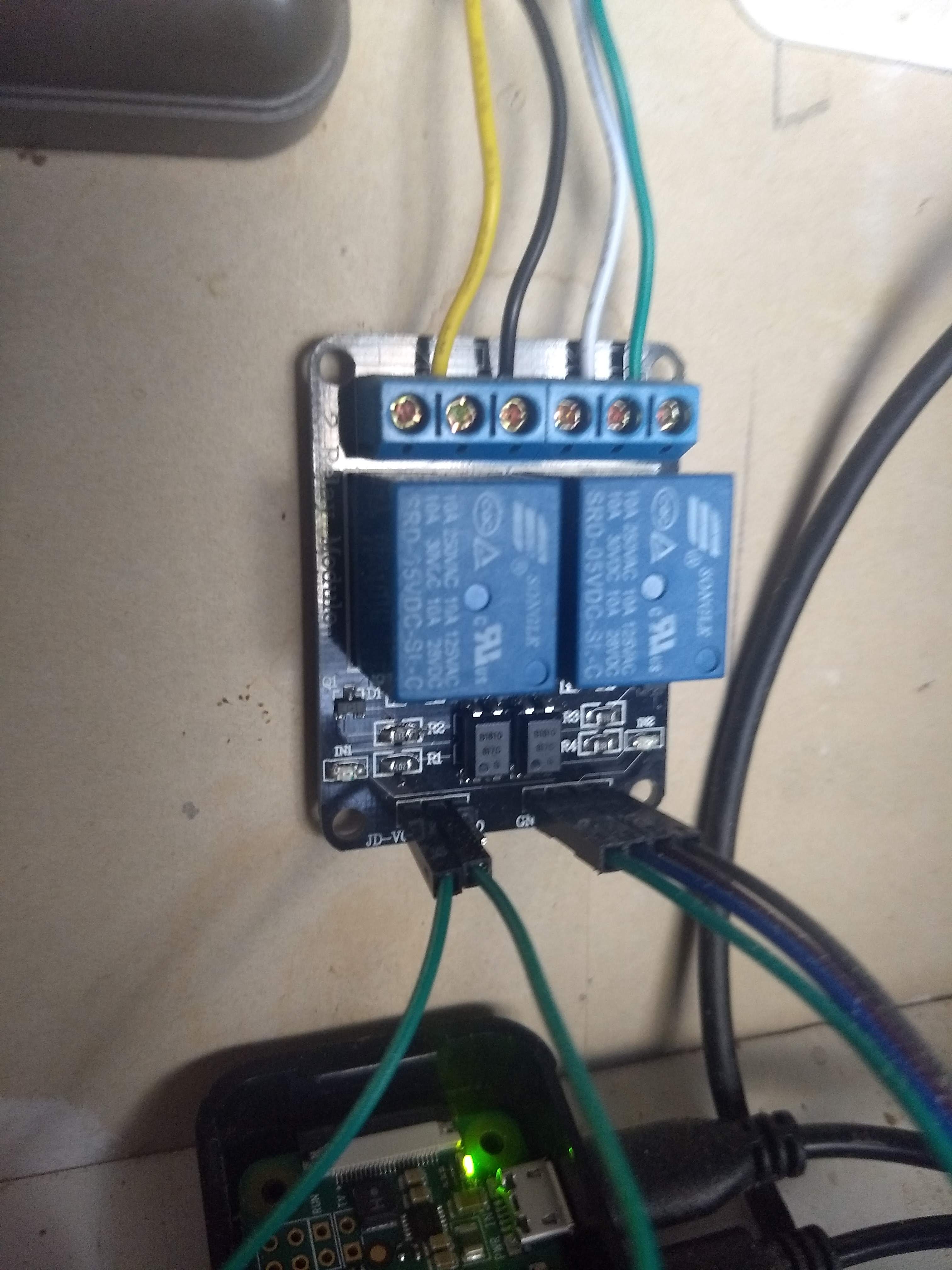
Not too much to say here, just connect everything up like in the pictures. On the Sainsmart 2-relay module, the JC-VCC and VCC pins need to be jumpered together, unless you want to use a completely separate power supply for them, but for this use, that's way overkill. Connect GND to a Pi GND pin, VCC to a 5v pin, and the IN1 and IN2 to whatever GPIO pins you want to use. Since you're just going to using them as HIGH/LOW toggles, it really doesn't matter which ones.
Installing the Software
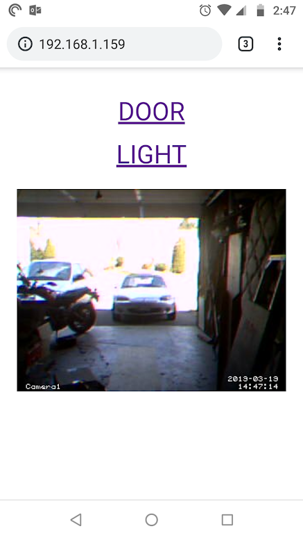
This is probably the most time consuming step, since you're going to be watching things download and install for a while. Watch youtube or something while some of this stuff is installed.
I'm not going to explain how to install Raspbian. If you don't know how to do that yet, maybe go google some "hello world" type of tutorials first. In any case, it's probably best to use a fresh install of Raspbian Lite. There's no need for a gui for this project, and it's just extra overhead. raspberrypi.org can walk you through that process.
Enable SSH, and (if you like) either configure a static IP for your Pi (once again, there are multiple tutorials out there on how to do that, written by better authors than myself) or even better, configure your router/DHCP server to assign a static IP to your Pi.
If you want a nice, easy to install and use video service, go and install MotionEye. It's probably overkill, but it's one of the installs that "just works" every time, and it has a nice easy to use web interface. Check it out here:
https://github.com/ccrisan/motioneye/wiki/Install-... Follow these instructions using sudo before each command, and you'll have a nice video streamer set up. It's not exactly required to have a video stream if all you care about is opening your door when you can see it, but it's nice to have feedback.
Once you have Motioneye installed, visit http://YourIPAddress:8765 and login with the username "admin" and a blank password. You'll probably need to add a camera, which should, again, "just work" and beyond the scope of these instructions.
While you are logged in as admin, click the "Advanced Settings" toggle, then set your video options - I used 320x240 for my video because I care more about faster updates than I do about quality, since I really only wanted to see it the door was open or not, and don't need to read mailbox numbers across the street.
Under the "Video Streaming" settings area, click the "Streaming URL" link, and make a note of the address that it presents to you. You'll need it later if you plan on setting up the Interface in the same way I did.
There are multiple ways to control your GPIO pins. For this project, I used WiringPi, to install it, use the instructions on the website:
http://wiringpi.com/download-and-install/
Or just issue the following commands on your Pi:
wget  https://lion.drogon.net/wiringpi-2.50-1.deb
sudo dpkg -i wiringpi-2.50-1.deb

gpio -v
gpio readall
This should give you a list of what's going on with your GPIO pins.
If you're using pins 4 and 17 (in the BCM numbering scheme), you can test your connections with the following commands. Note that setting the pin LOW will activate the relays if using this Sainsmart module. Yours may be different, and you'll need to adjust for that. When running these commands, you should hear the relays click into place, and the LED(s) should light up.
gpio -g mode 17 out
gpio -g write 17 0
gpio -g write 1 1
gpio -g mode 4 out
gpio -g write 4 0
gpio -g write 4 1
OK, now we can move on to making the UI.
Making the Interface
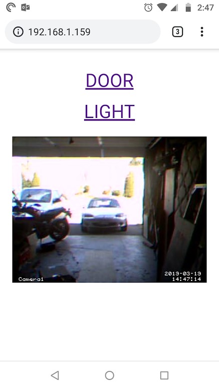
I used apache and PHP. Nice and simple, nothing too fancy. Once again, it's been better explained elsewhere, so just follow the instructions found here:
https://www.raspberrypi.org/documentation/remote-a...
The "root" of your webserver, by default, is at /var/www/html/ with a default index.html that gives you info about your webserver. You'll be replacing that index.html, so you can either delete it or rename it to something else like index.copy. I also made the "pi" user the owner of the html directory, just to be lazy about permissions. Finally, I created a directory to store my images, of which there are two. One that's just silly feedback that a button was pressed, and another that can be used for an icon on a phone home screen.
pi@garagedoor:~ $ cd /var/www/html/
pi@garagedoor:/var/www/html $ sudo chown pi .
pi@garagedoor:/var/www/html $ mv index.html index.copy
pi@garagedoor:/var/www/html $ mkdir images
There are an infinite number of ways to create a website, but I chose to keep it as simple and easy as possible based on MY skillset. Hence, PHP, since I know it. If you're a python guru or some other scripting language, feel free to use that.
I created a "container" index.html page which actually has two iframes that do all of the work. One of the iframes contains the buttons/links that actually trigger the relays via GPIO, and another iframe that displays the video. It also contains links to a .png image than can be used as a phone's homescreen icon.
The index.html iframe containing the buttons has the file buttons.html as its content. (funny how that works, huh?) Both of the links in button.html lead to action.php with a unique GET variable value. Based on the value passed, action.php will either trigger the door or the light button. You can get the HTML and PHP code from my github: https://github.com/mrbigbusiness/pi_garage_door
Place all of the HTML and PHP in the root directory (/var/www/html/), update the code where needed with the name of the image you may be using for button-press confirmation, and the address of your video stream. Remember when I told you you'd need that, back in the previous step?
Try It Out!

OK, now that you have everything wired up and installed, it all works perfectly on the first try, right? Sweet!