Raspberry Pi Air Quality Monitor
by jacobverschaeve in Circuits > Raspberry Pi
10297 Views, 21 Favorites, 0 Comments
Raspberry Pi Air Quality Monitor
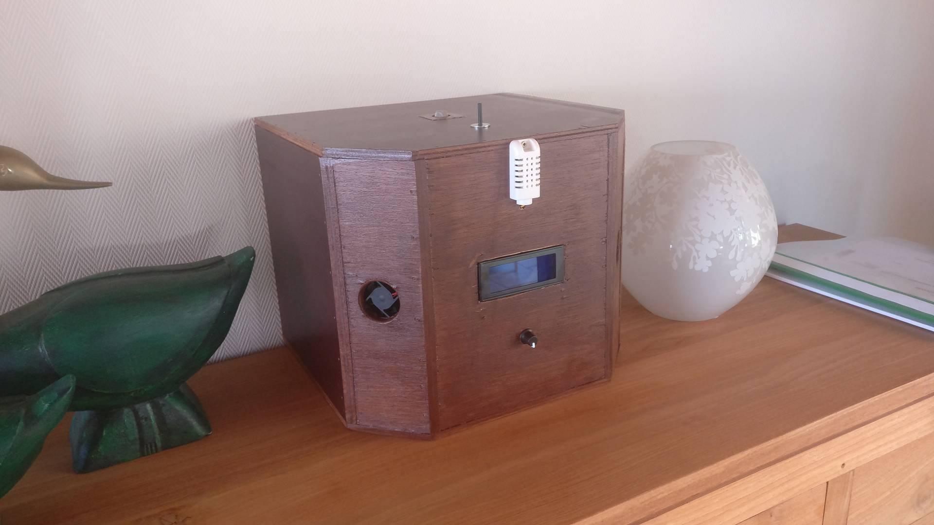
I had the assignment to make an Air Quality Monitor.
I'm a student at Howest Kortrijk and studying NMCT which stands for New Media Communication & Technology.
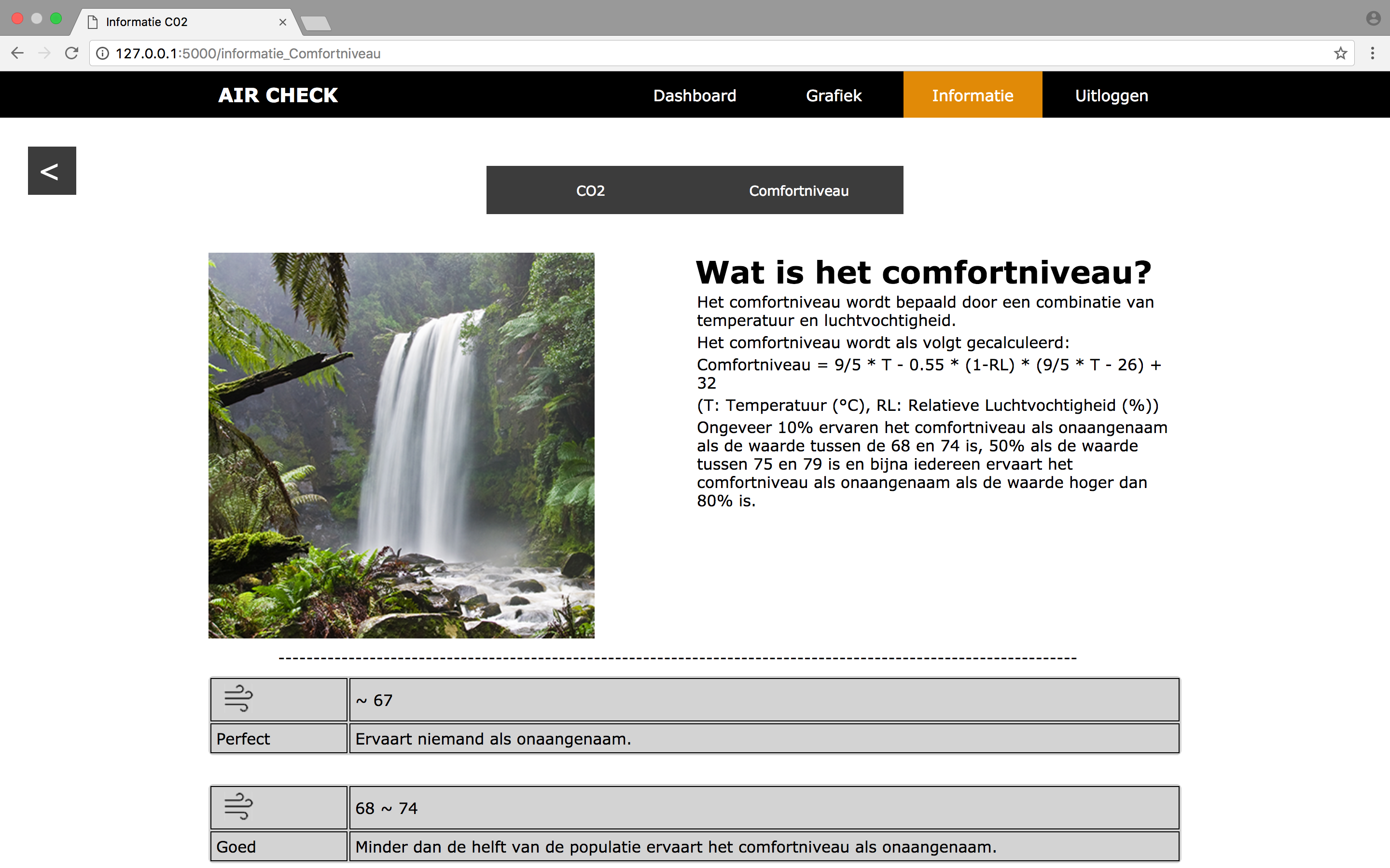
My Air Quality Monitor gives you information about the temperature, humidity and carbon dioxide level. The sensors are connected to a Raspberry Pi. The values of the sensors are displayed on a website which is written in Flask (PyCharm). The most recent value is displayed on the 4x20 LCD display. It also gives a another value which is called "Comfortlevel", this is a calculation of the temperature and humidity.
In this instructable, i'm going to give you every single step to create the air quality monitor.
Materials
- MQ135 (Carbon Dioxide Sensor)
- AM2302 (Temperature and humidity sensor)
- Fans 12V/DC (2x)
- Potentiometer (10K) (1x)
- Raspberry Pi
- LCD Display 20x4
- MCP3008 (ADC Convertor)
- Jumper Wires (40M/M Wires)
- 100 ohm resistor (2x)
- Potentiometer (100 ohm)
- 12V/DC Adapter
- Wood & Tools
In total this will cost around 120 euros. All the materials can be found on AliExpress, Amazon or your local shop.
Downloads
Wiring
You can see a good overview of the wiring on the attachment called Wiring.fzz
The .fzz extension can be executed in the program Fritzing. This is a free open source program.
My sensor called MQ135 isn't available on Fritzing, i used another sensor which works the same way like it. The MQ135 has 4 pins, but you only have to connect 3 pins. We have a 5V pin, GND, analog out and digital out.
Connect the 5V pin with the 5V of the Raspberry Pi. The GND connected to the GND of the Raspberry Pi. The analog out pin is connected to a free slot of the MCP3008.
Please note:
- The wiring of the fans are independent of the wiring connected to the Raspberry Pi.
- T-Cobbler is connected to the Raspberry Pi
- I used a 12V power supply, you can also use a 12V battery but after a while the battery will not have enough power to turn the fans at the desired speed.
Downloads
Database

The application needs a database too, i have used MySQL.
The .xml file gives you a good overview of how the database looks like. (You can open this on the site draw.io) We have the user table which is connected to the sensor tables. The CO2 and the temperature, humidity and comfort level are located in another table. These tables are connected to a table which controls the time between the measurements. You can't save all the sensor values in the same table because you can change the time difference between the measurements of the different sensors. That's why i separated the CO2-value of the other ones.
You can use the .mwb file to synchronise it with your database in MySQL.
Install the MySQL database on the Raspberry Pi
Before we get started we need to check if the Raspberry Pi is running on the latest software:
sudo apt-get update && sudo apt-get upgrade
First of all we have to install the MySQL server:
sudo apt-get install mysql-server
If we want to connect to the MySQL server, we also need a client:
sudo apt-get install mysql-client
If you want to connect to the database type in the following rule:
mysql -uroot -p
Adding new user to MySQL (See screenshot)
Now it's time to run my sql-dump
The dump file is included on this step which is called "Air_Check.sql"
QUIT MySQL
Install the MySQL connector so we can connect via PyCharm to the MySQL database on the Raspberry Pi
sudo apt-get install python3-mysql.connector
Coding Sensors and Website

Link to my code of the sensors:
https://github.com/jacobverschaeve/Code
Link to my code of my website:
https://github.com/jacobverschaeve/Code_Website
All my codes are written in PyCharm.
Download the code in the directory you want on your Raspberry Pi:
git clone https://github.com/jacobverschaeve/Code
git clone https://github.com/jacobverschaeve/Code_Website
Please note, my code is connected to my database. You can change this to your favour.
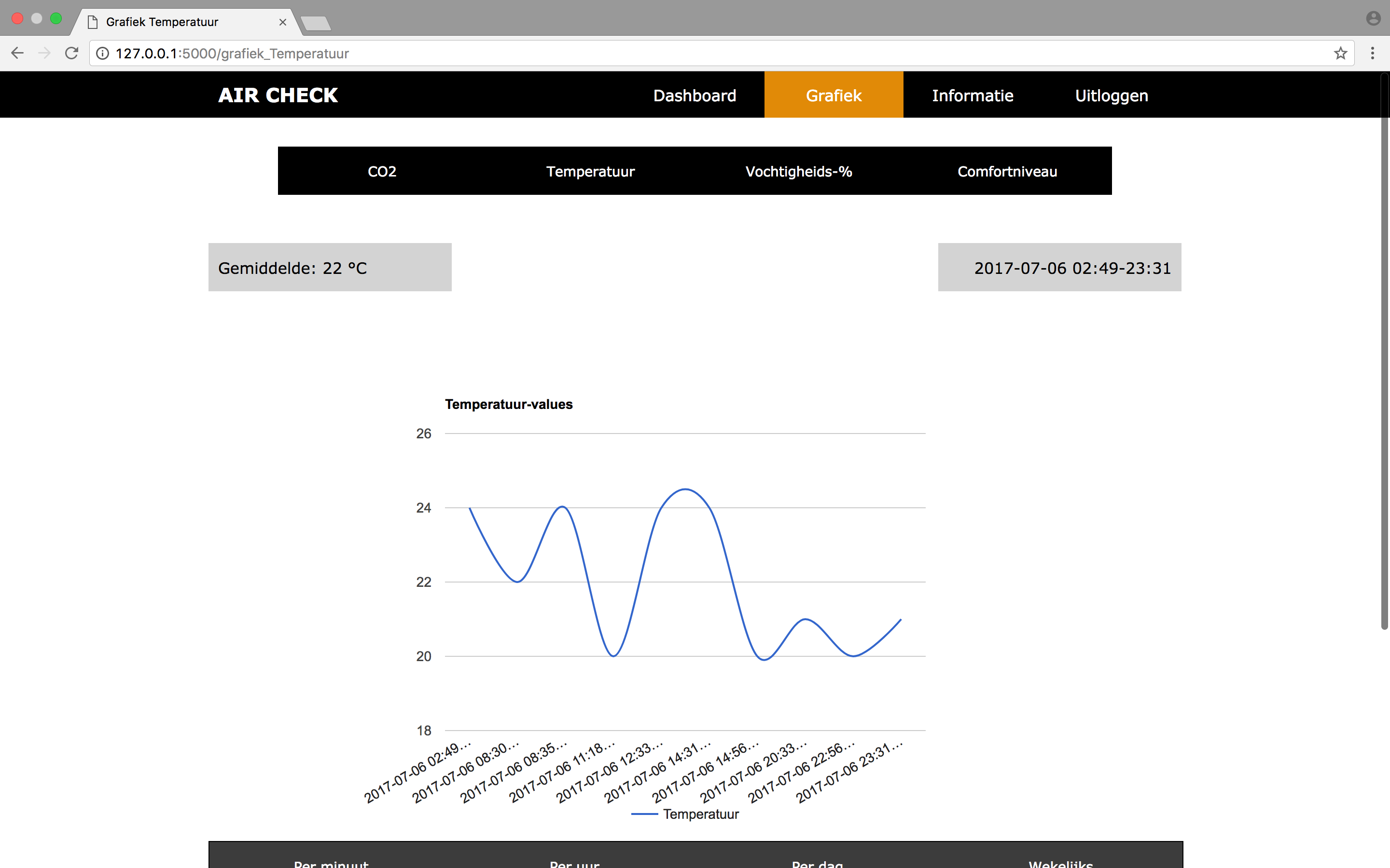
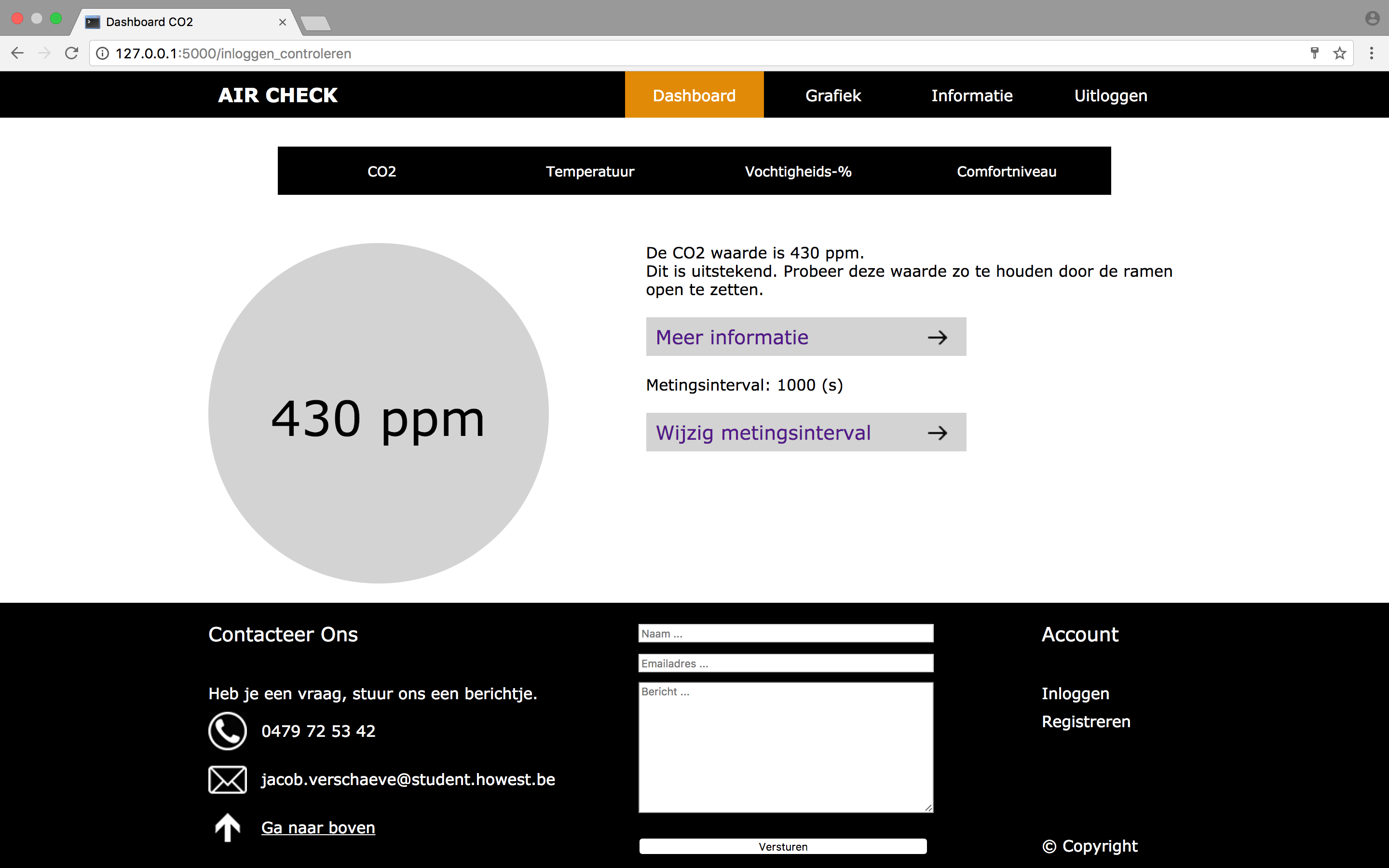
The site will show you an overview of the last value that the sensor had read. It also gives you a chart of the last 10 values. Some of these values will say nothing to you, that's why I included a information page.
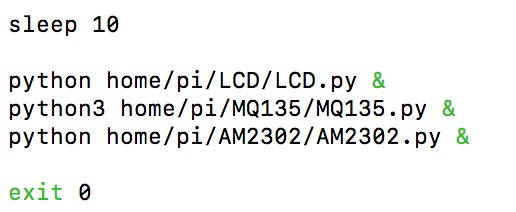
If we boot up the Raspberry Pi we want to start all our scripts.
We can do this easily to place our scripts in the "rc.local" file.
cd /etc
sudo nano rc.local
Watch the screenshot how I did, it's important to type sleep 10 before we start the scripts. This is because MySQL needs also some time to boot up.
Housing of the Application
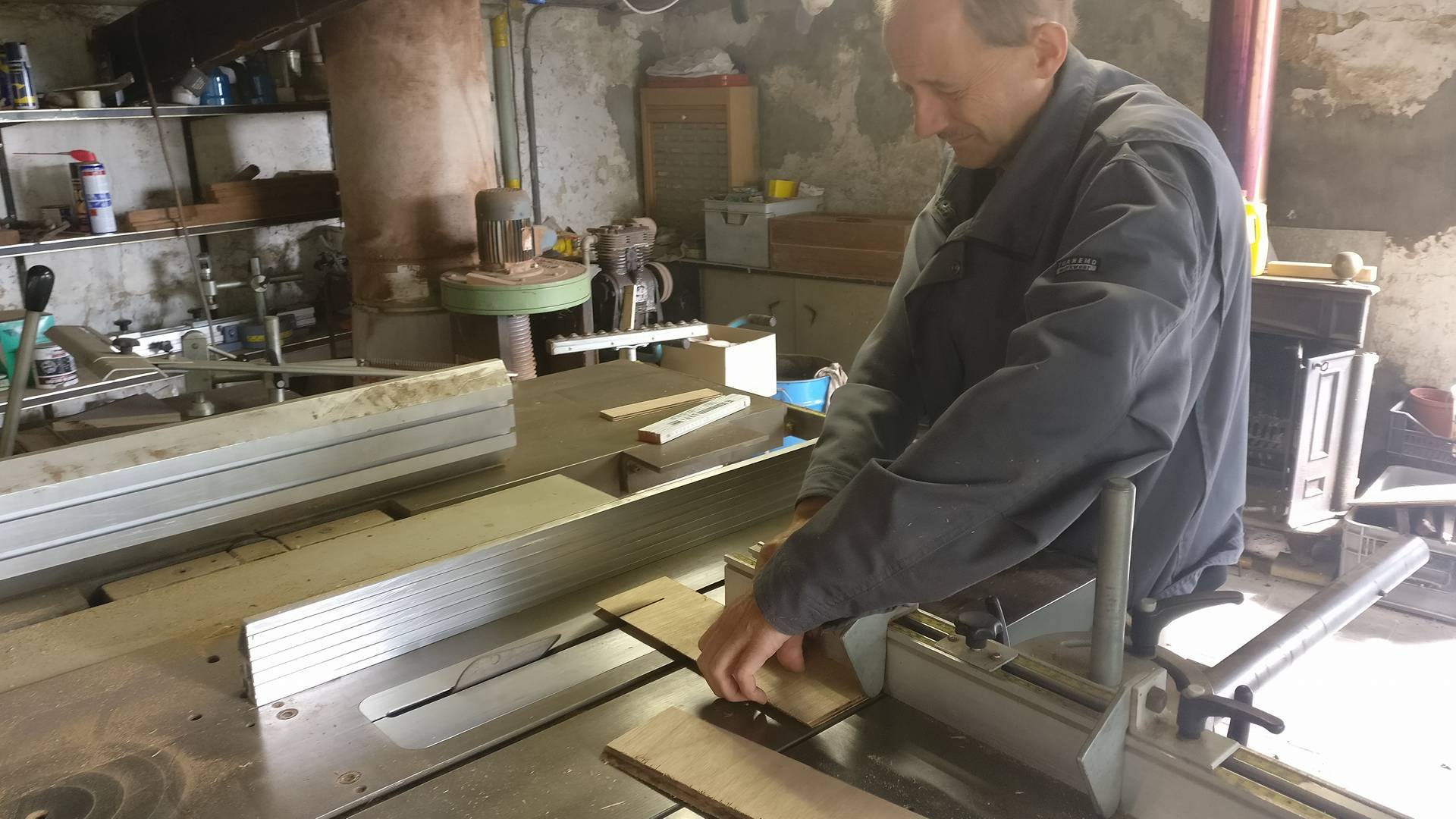
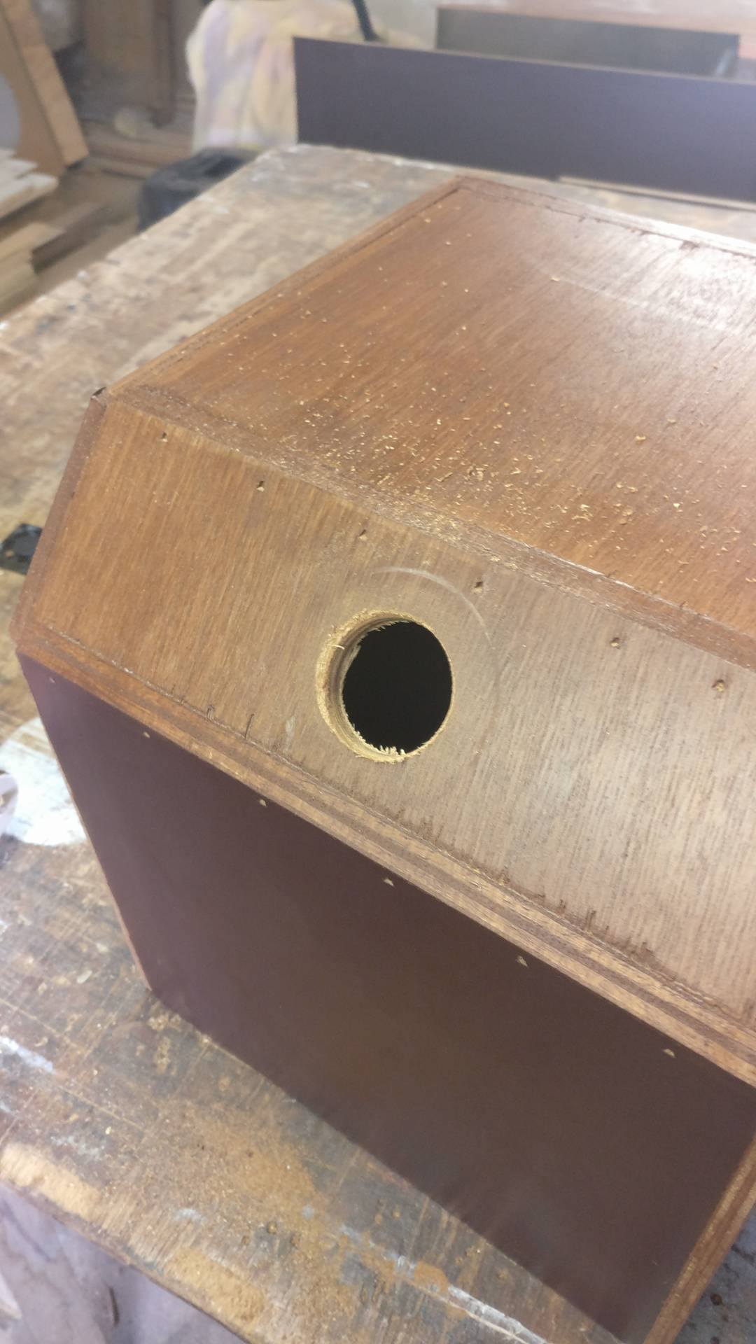
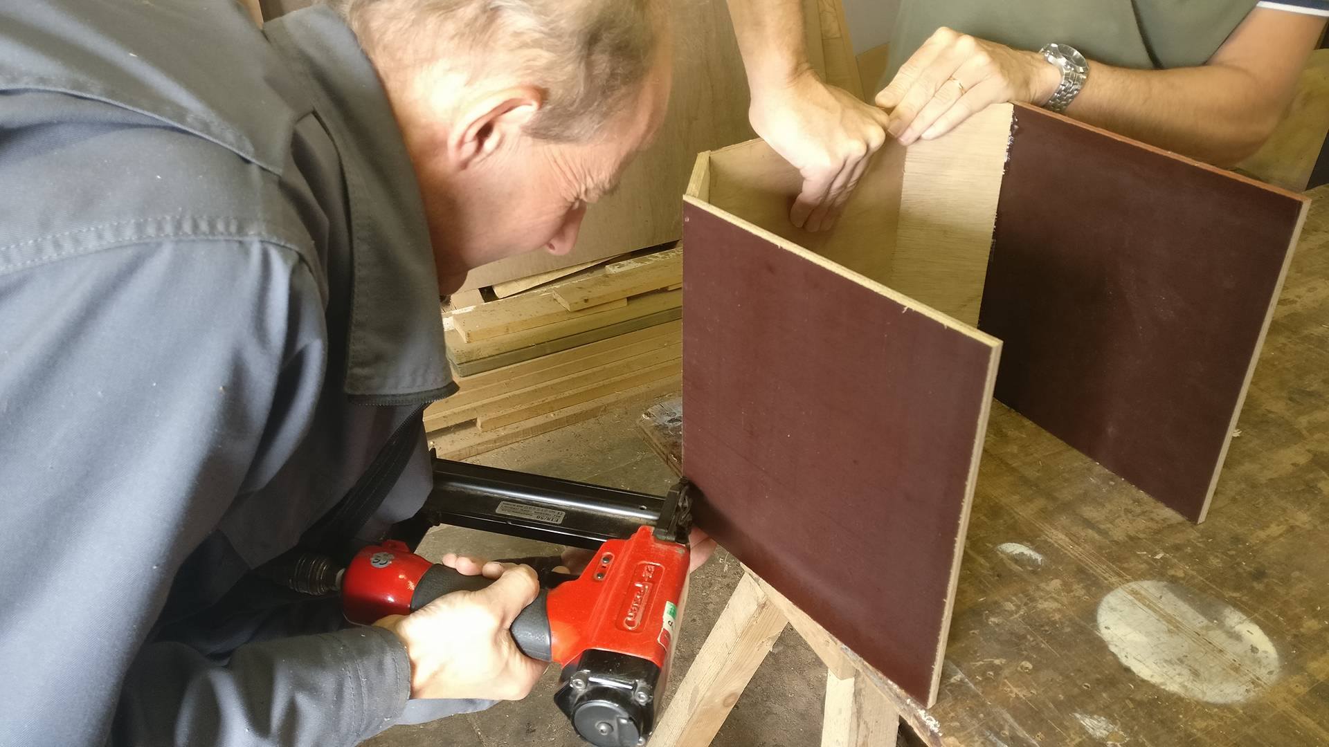
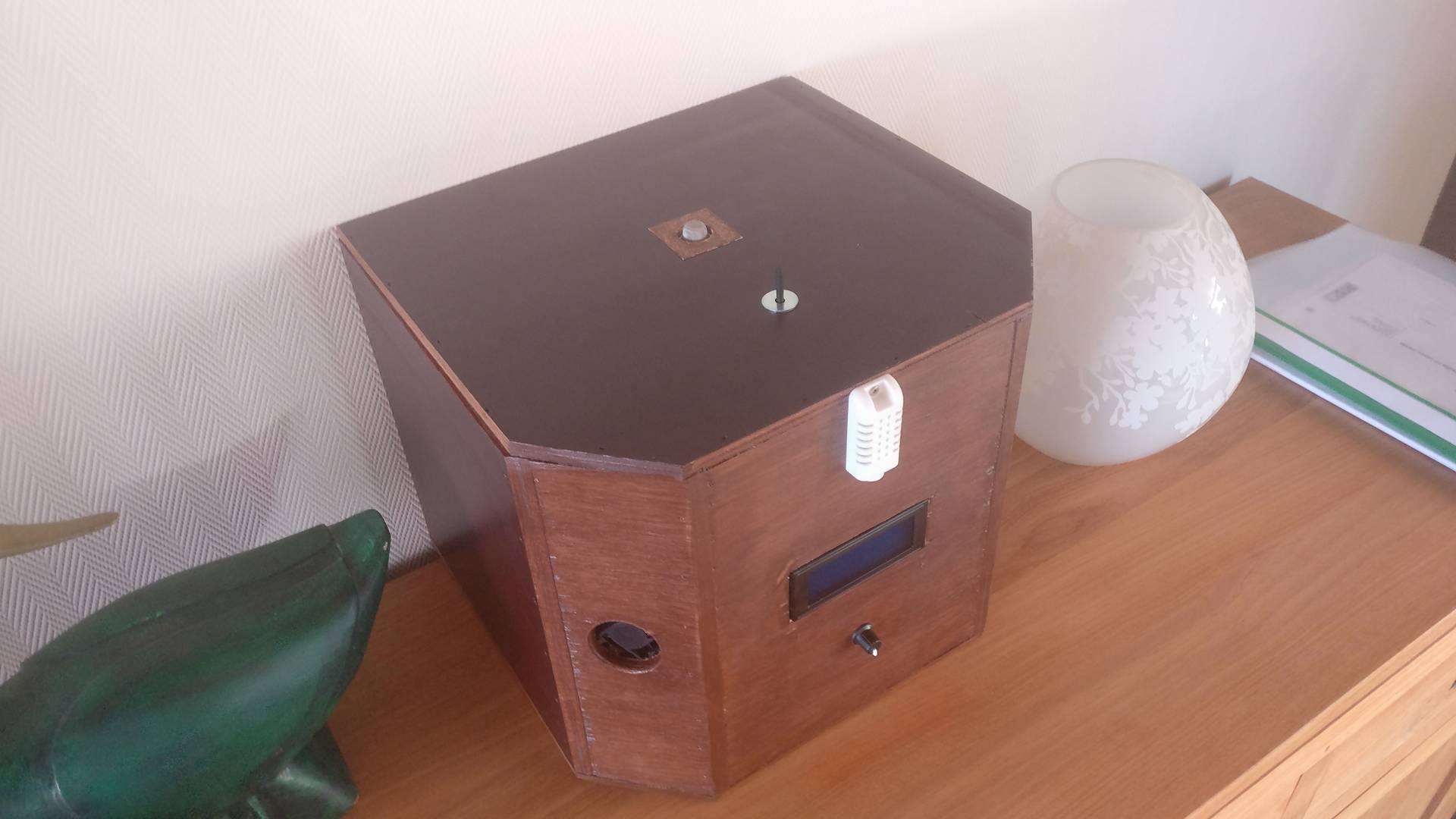
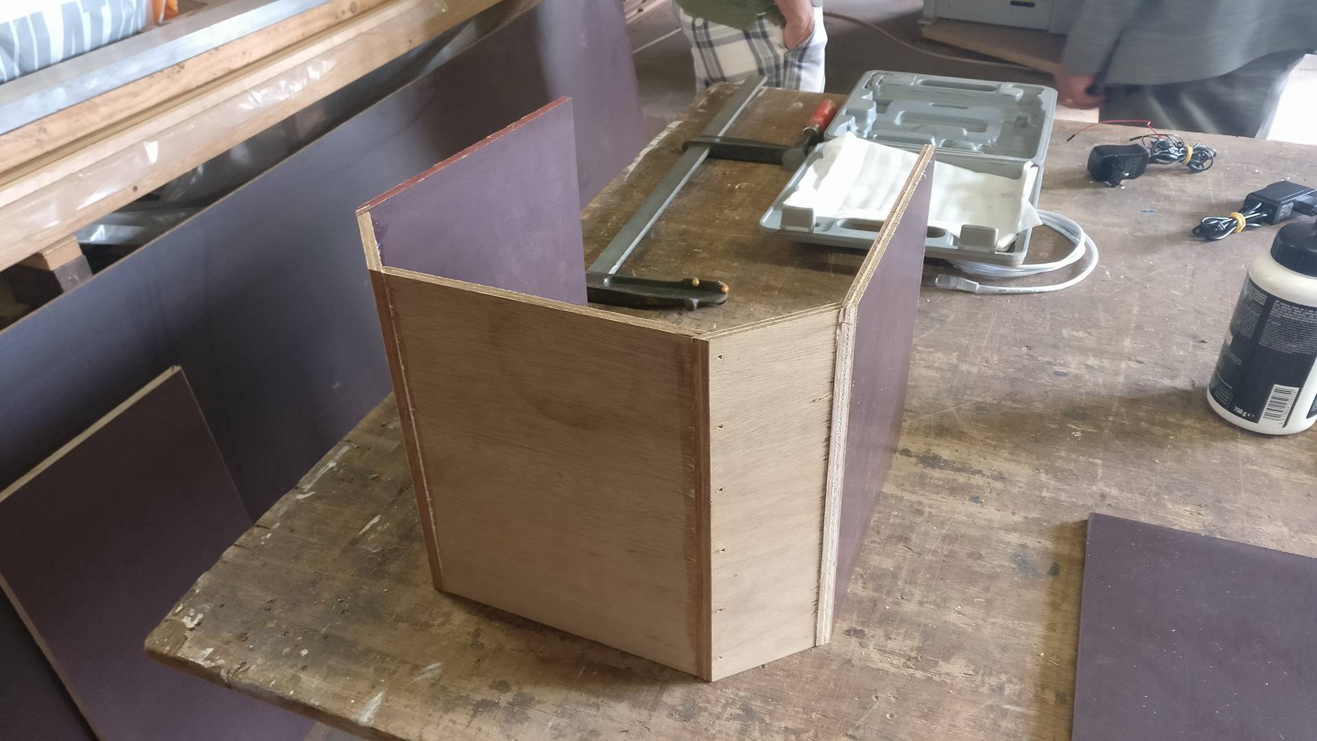
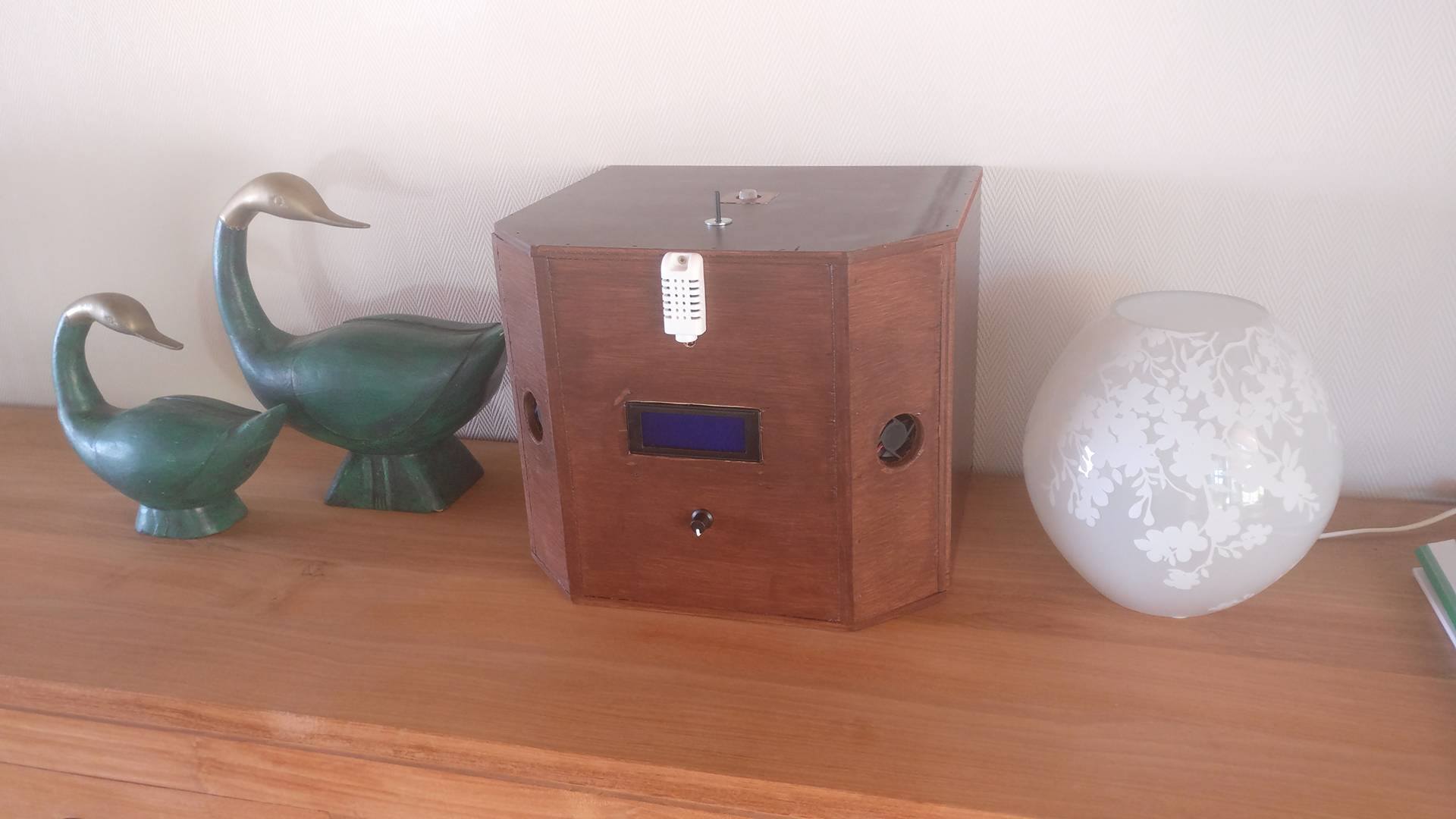
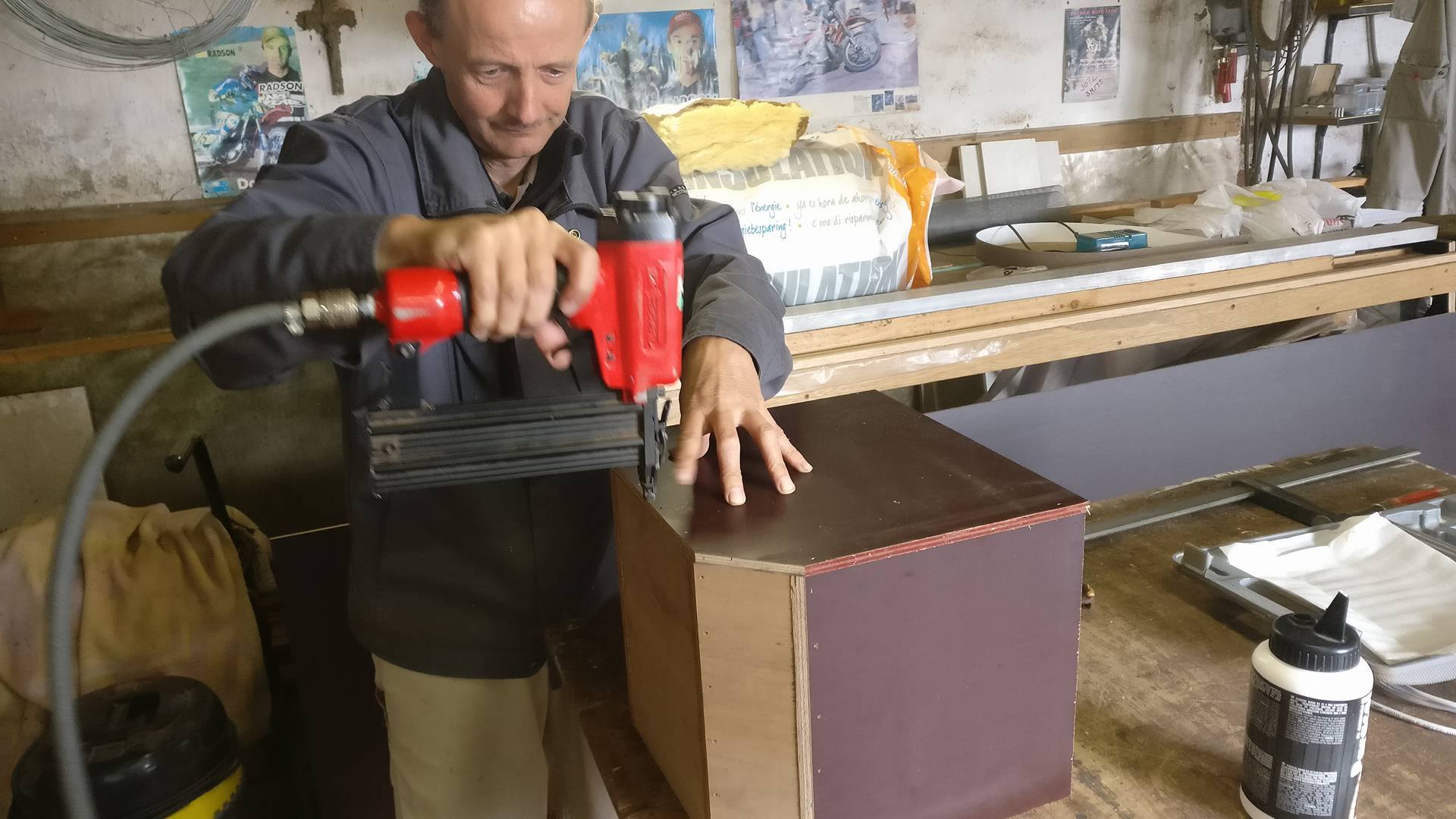
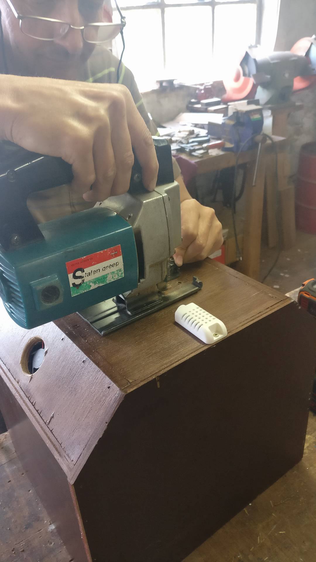
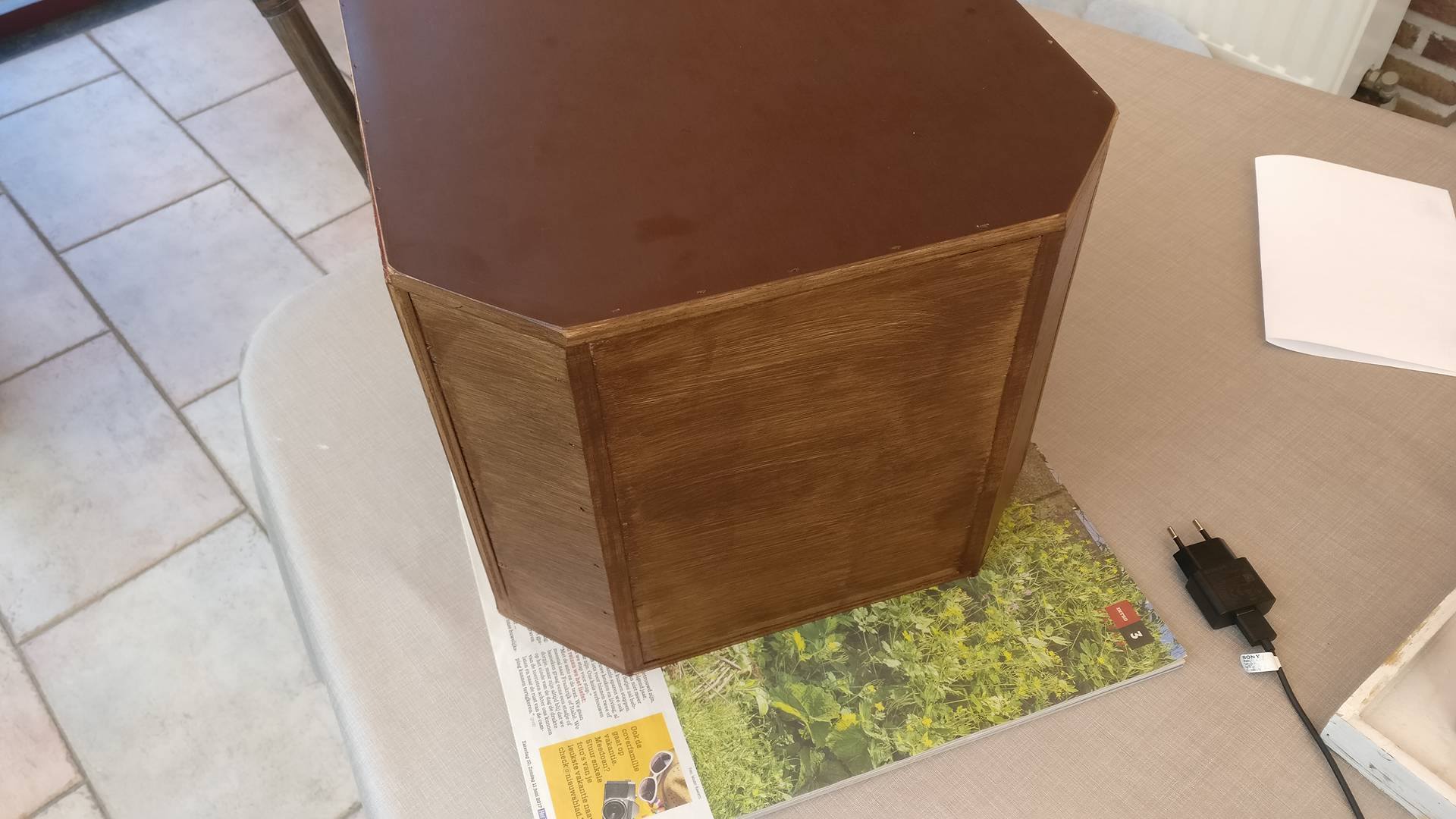
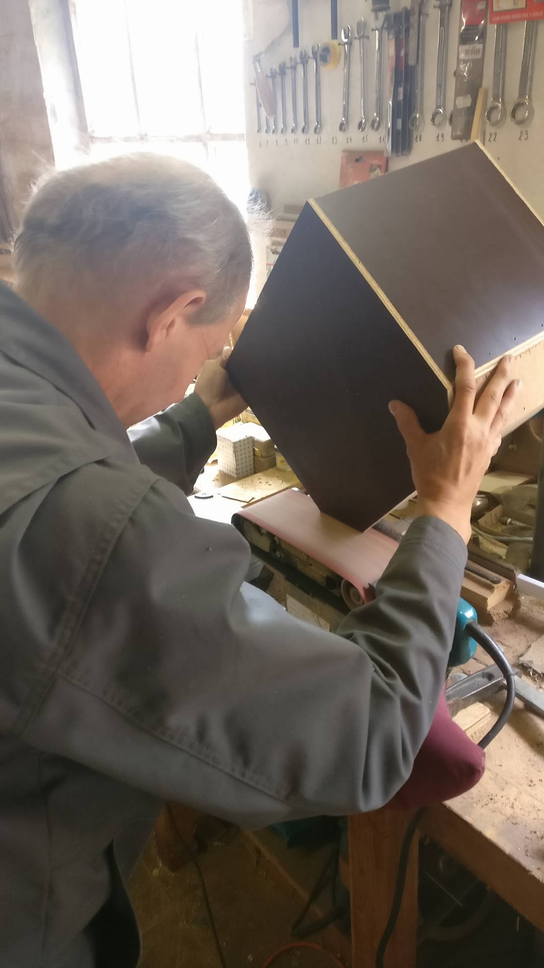
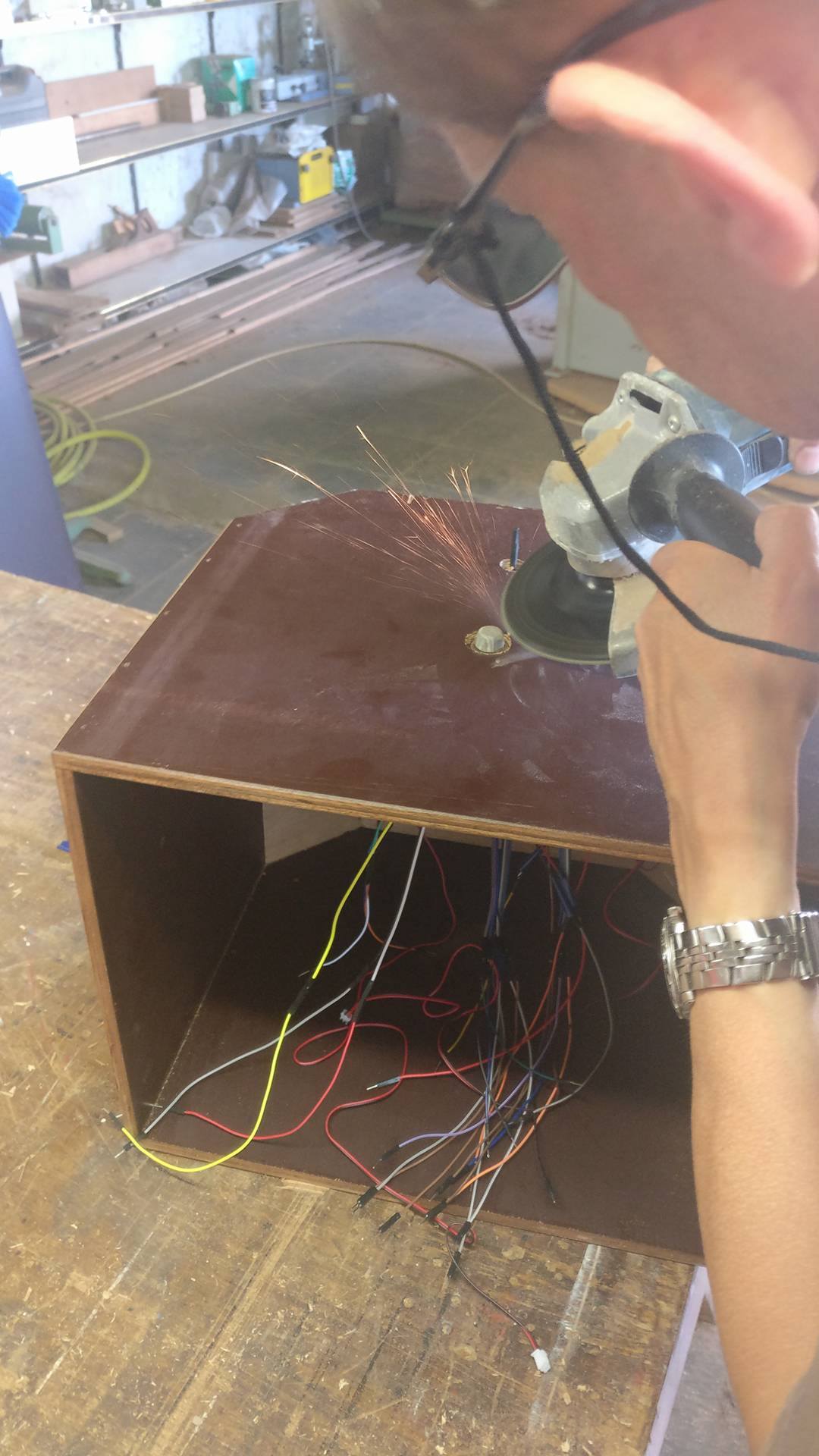
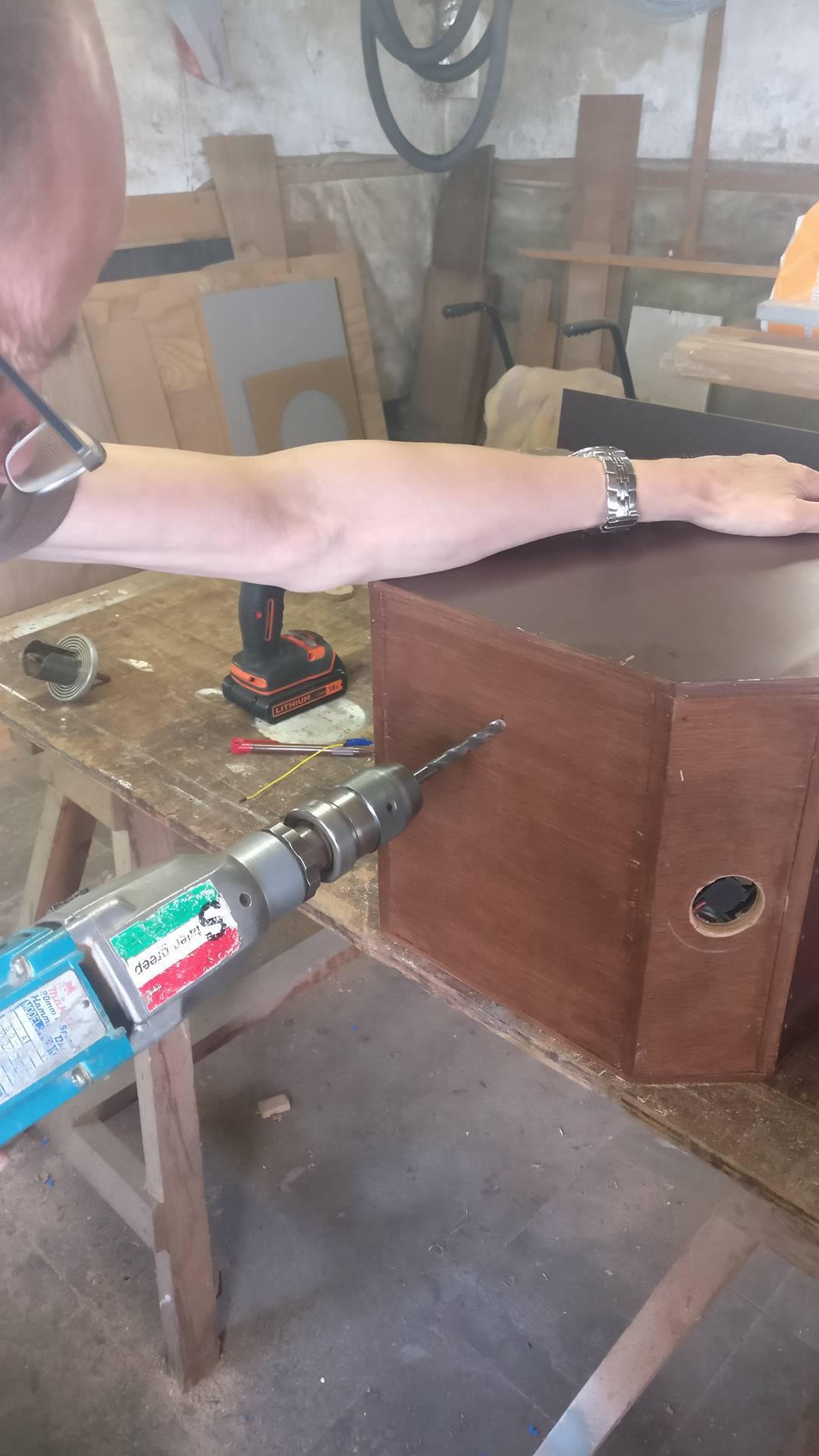

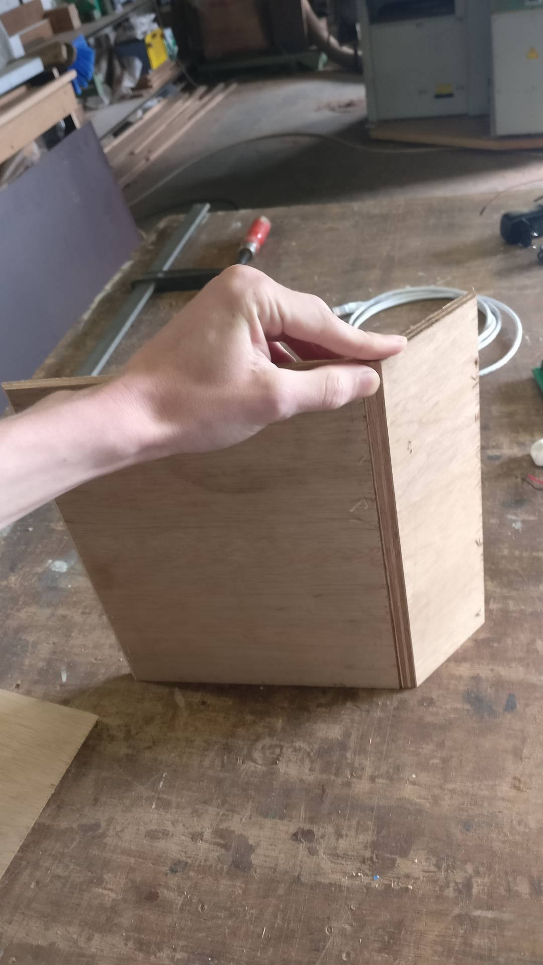
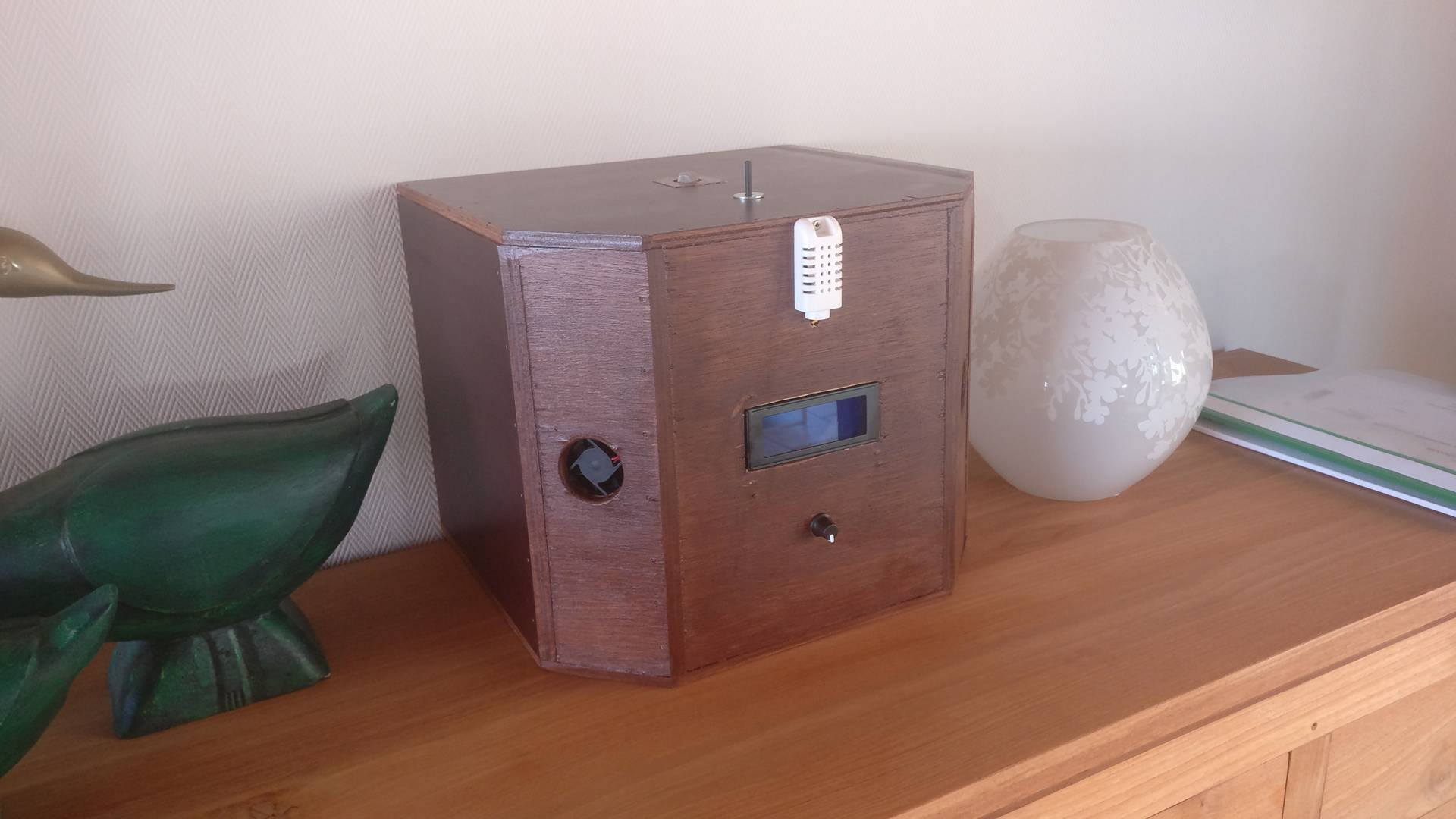
I had the opportunity to make my case a little bit more special. I had the idea to build-in my fans at an 45° angle. This makes it hard to build such a case. If you don't have the machines to make such an angle, you can just make a square box.
For the housing you need:
- Wood
- Saw
- Nails
- Nail shooter
- Sander
- Oil
- Paint brush
I will show you how I did it, feel free to change the design to your capabilities.
1. Cut the wood in the shape you want (45° angles if you want)
2. Attach the shapes together via a nail shooter, hammer or screws; whatever you want.
3. Sand off the pieces which aren't perfectly aligned with the other shapes.
Now the box is ready to cut out several gaps for the sensors and cables.
(I oiled the wooden planks in front to give it a nicer texture.)
4. Cut out the parts where the sensors come out, you can store the electronics within the case.
This is the hardest part, you can go as far as you want at this point.