Raspberry PI Autobot Transformer (Non-Transformable)
by dailodai78 in Circuits > Raspberry Pi
11839 Views, 57 Favorites, 0 Comments
Raspberry PI Autobot Transformer (Non-Transformable)
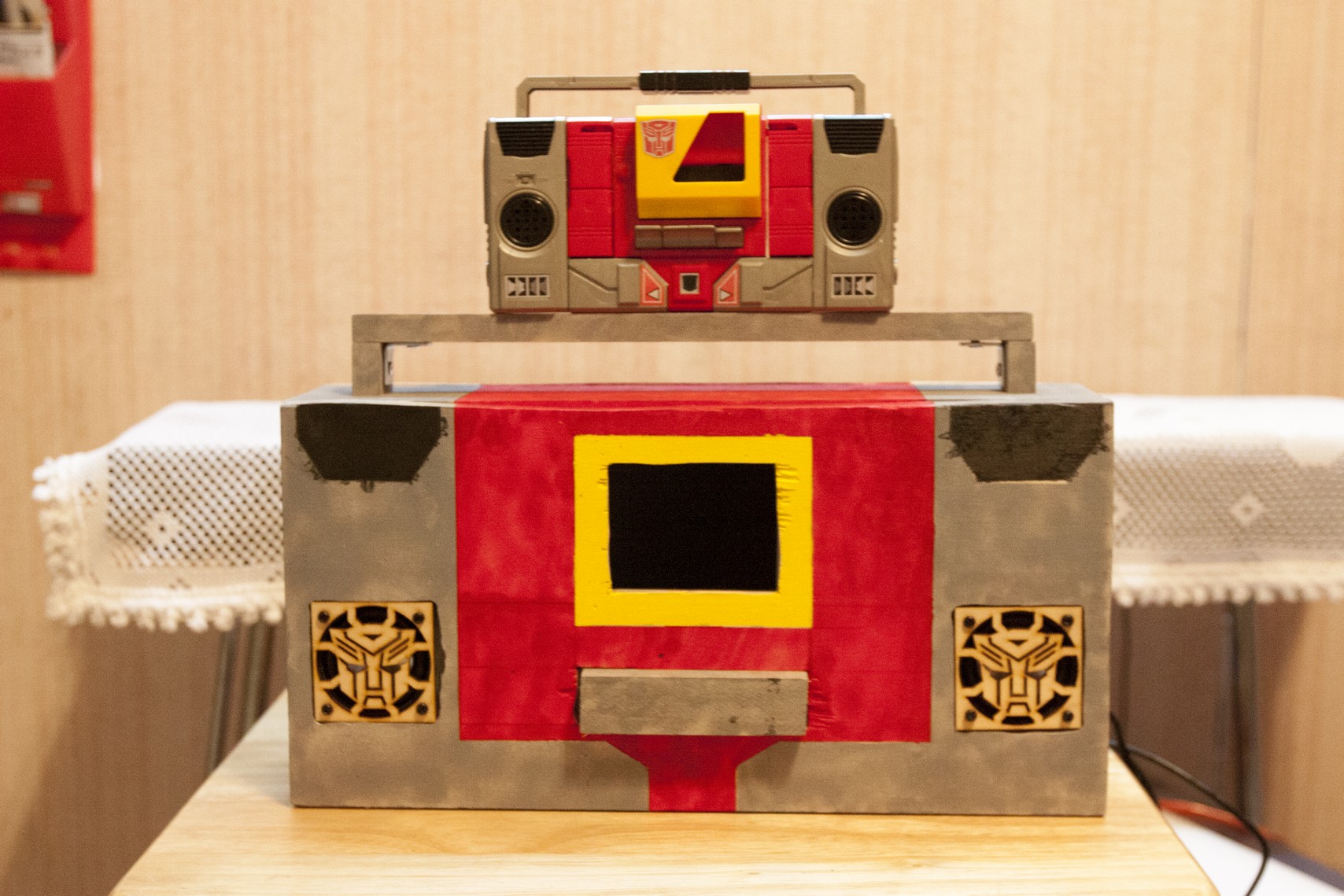
Wish that the Autobot Blaster Transformer could play music when you were a kid? Well now you can with this Instructable!
ABSOLUTELY NO PROGRAMMING SKILLS NECESSARY :)
This Instructable shows you how to create a Classic Boombox with a Raspberry Pi.
The model that is being used for this project is the Autobot Blaster Generation 1 from Transformers.
In the following steps, I'll show you step by step on how to design a larger scale model of the original Generation 1 Autobot.
Click here for the video demonstration of the finished product.
Internal Hardware
USB Keyboard - for configuration purposes only.
Raspberry Pi - $35.00
Enclosure - $7.35
SD card (2 GB, 4GB, 8 GB) - prices vary
Note - get a card that has a fast write. this will speed up the OS configuration settings.
Frisby FS-55NU USB Speakers - $7.95
- Note: For this project, get this speaker because it is cheap and it's loud for a USB powered speaker.
3.5" TFT LCD Monitor - $44.95 from Adafruit
- Comes equipped with dual RCA Video, and power plug (AC Adapter sold separately)
Female DC Power Adapter - $2.00 from Adafruit
Adafruit Mini Wi-Fi - $11.95
12 VDC 1 Amp AC Adapter (for 3.5 LCD Screen) - $8.95 from Adafruit
USB Hub WITH AC Adaptor ~ prices vary
- This is to provide extra power to the USB devices so the Raspberry Pi can recognize them.
2-3 32 or 64 GB USB sticks - prices vary.
Software
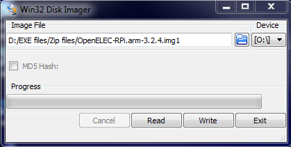
Software you need:
Click here to go directly to the Windows installation of OpenElec.
Here's the instructions for those who don't want to leave this page:
- OpenELEC XBMC player.
- XBMC Remote for Android / iOS
Click here to go directly to the Windows installation of OpenElec.
Here's the instructions for those who don't want to leave this page:
- Warning: Installing XBMC on SD Card will erase the current contents on the SD Card.
- Download Disk Imaging Software http://sourceforge.net/projects/win32diskimager/
- Download the latest OpenELEC Image http://resources.pichimney.com/OpenELEC/official_images/?C=M;O=D
- Insert your SD card into your system. It should appear as a new drive letter.
- Extract the image so you have a file ending in .img
- Extract the disk imager software and run Win32DiskImager
- Select the image file and verify the destination drive letter is correct, then click write.
Configuring the XBMC Layout
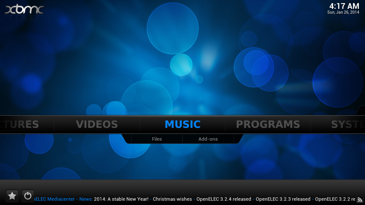
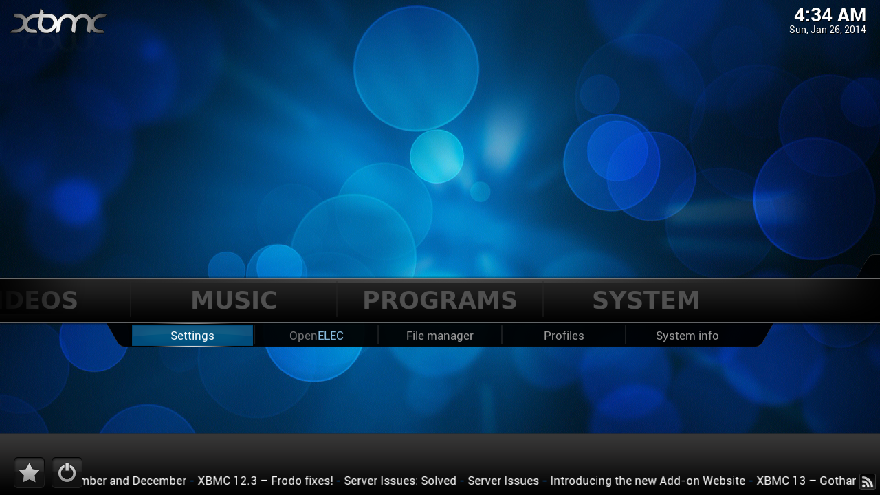
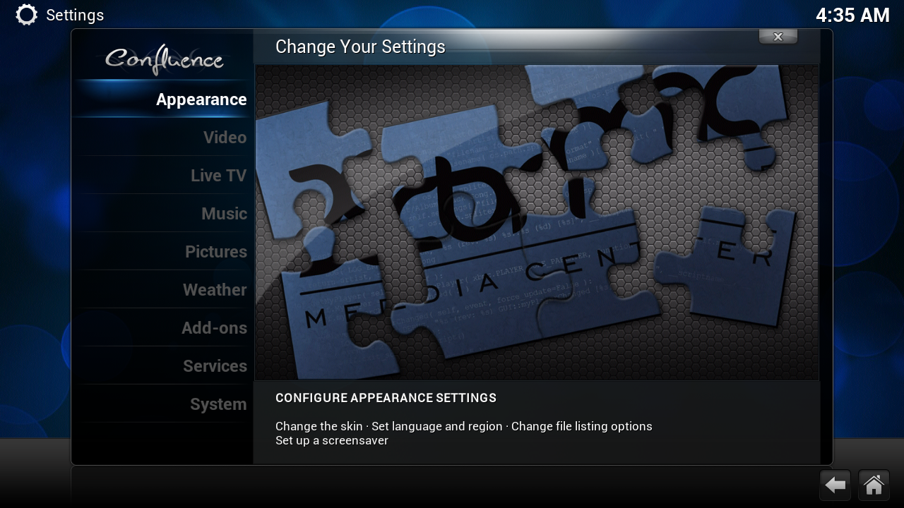
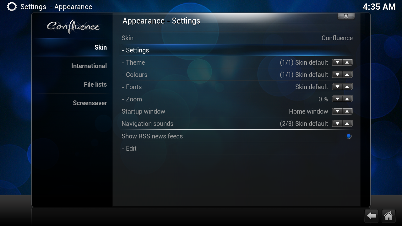
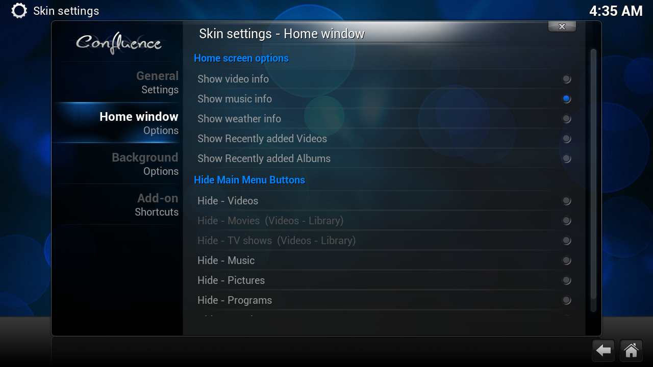
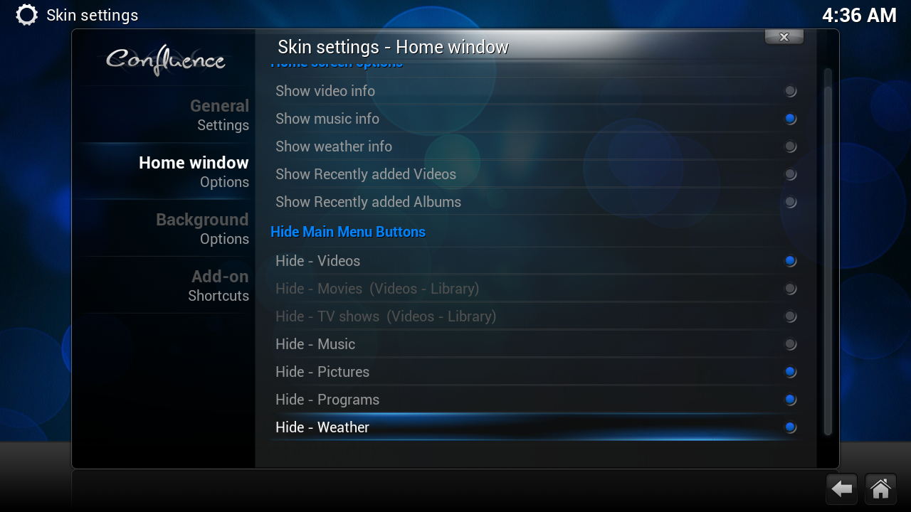
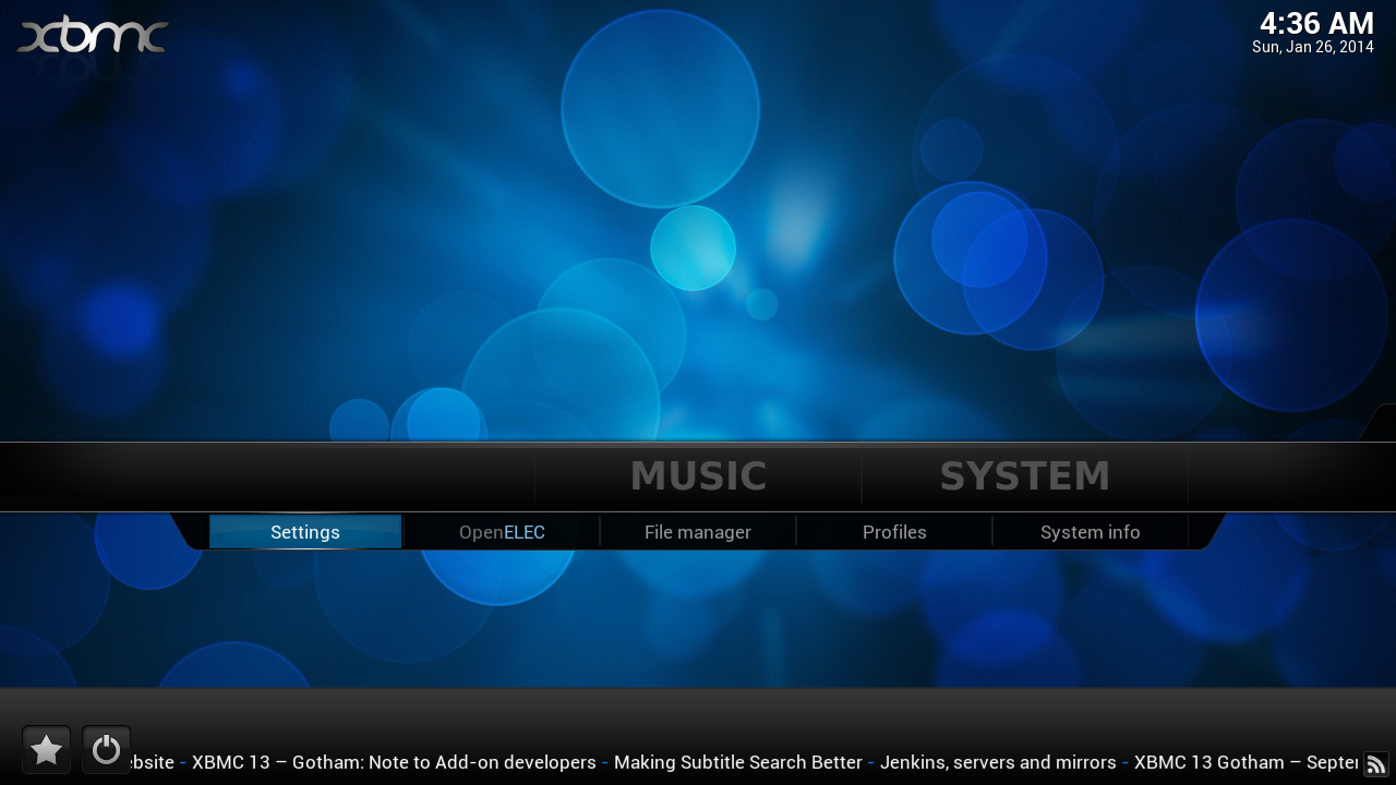
Once you have powered on the Raspberry Pi, please accept all the defaults and you should see the main menu.
You can leave it as is but since this is a music player, lets remove all the options EXCEPT the Music and System buttons.
You can leave it as is but since this is a music player, lets remove all the options EXCEPT the Music and System buttons.
- Navigate to System --> Settings
- Select Appearance
- Select Skin and navigate to Settings
- Select Home Window Options
- For the first section, enable only Show Music info
- In the next section, deselect everything EXCEPT Hide - Music
- Go back to the home screen and you should now see only the Music button being displayed.
Network and Web Server Configuration
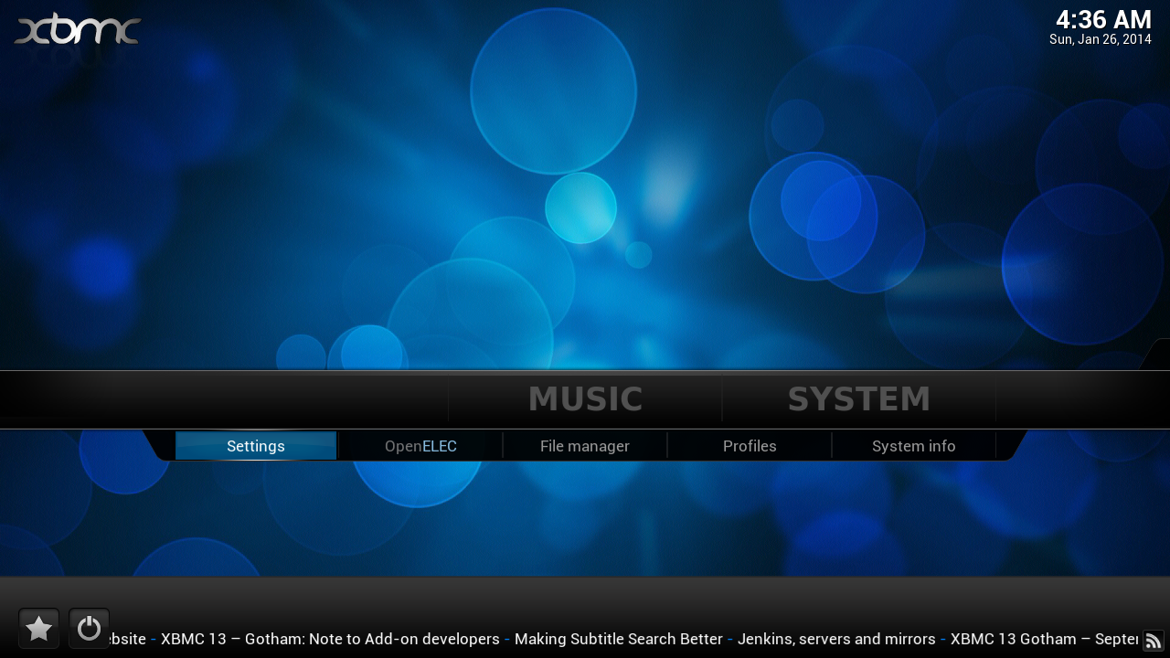
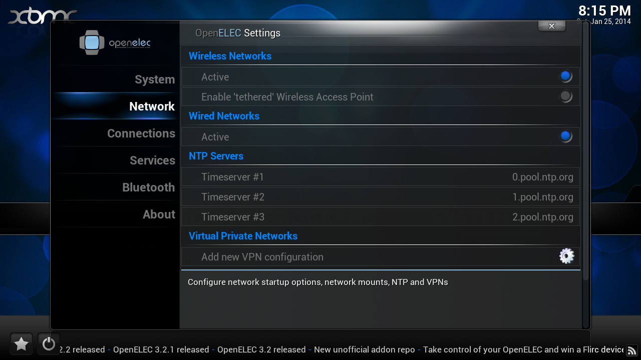
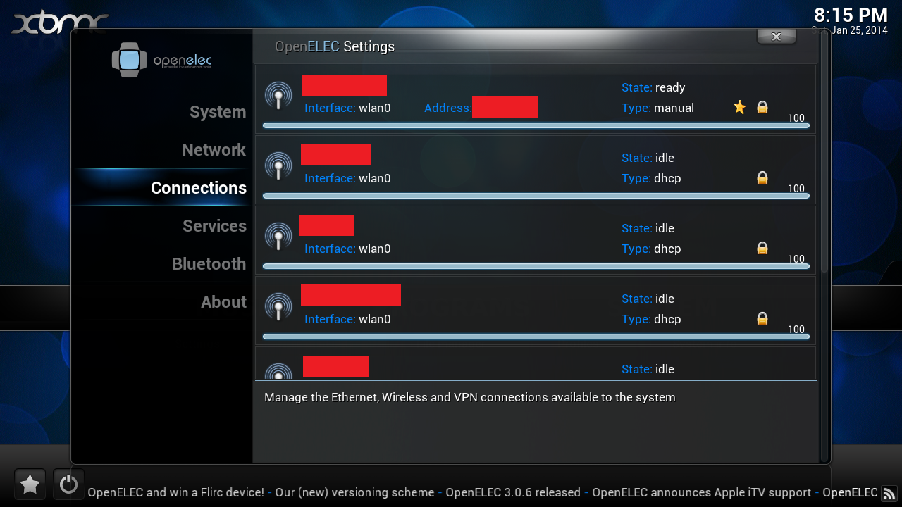
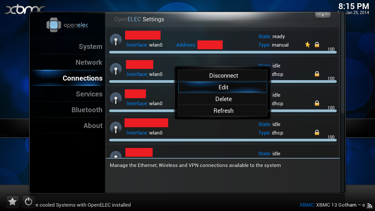
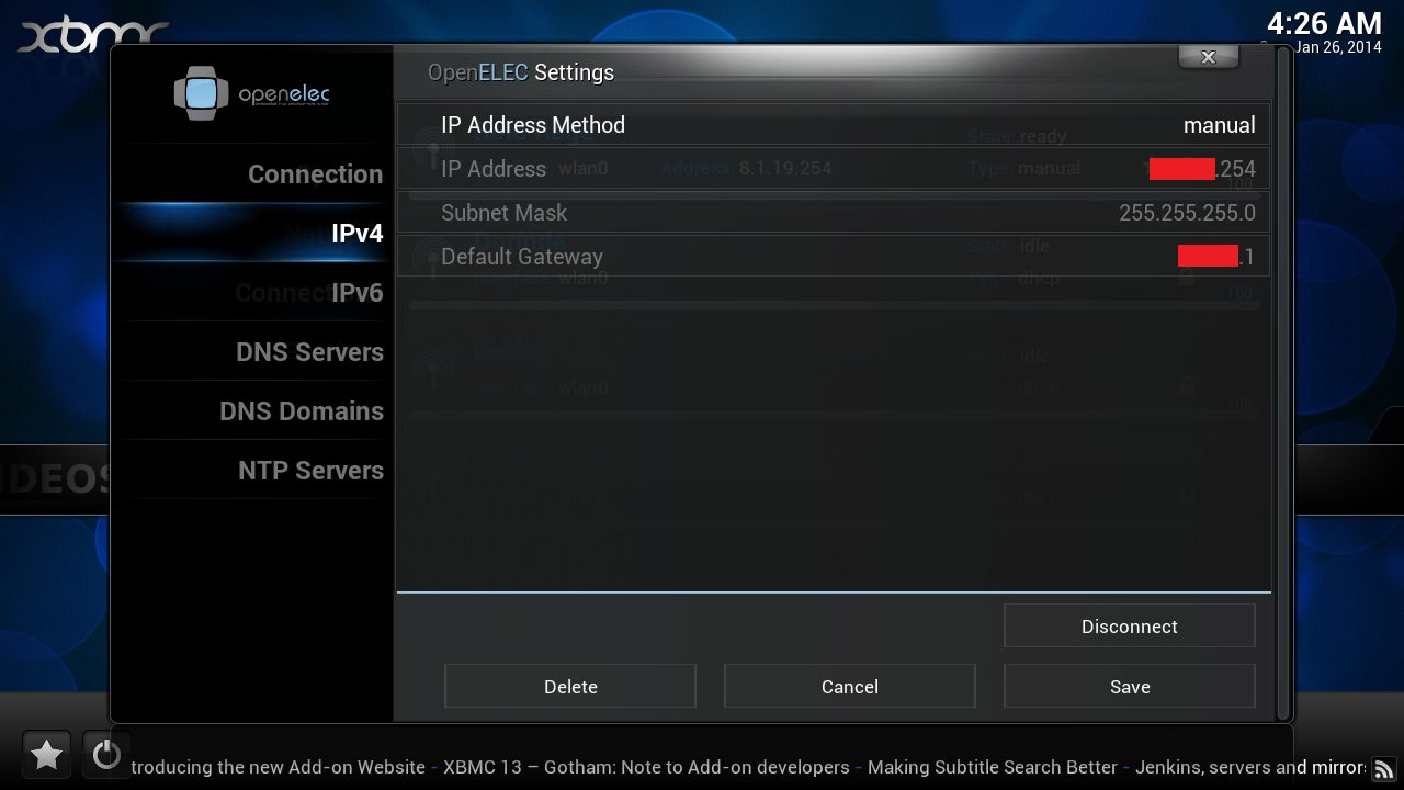
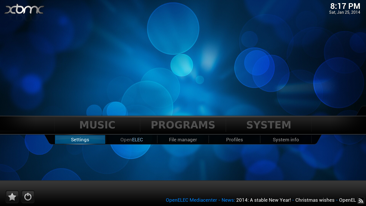
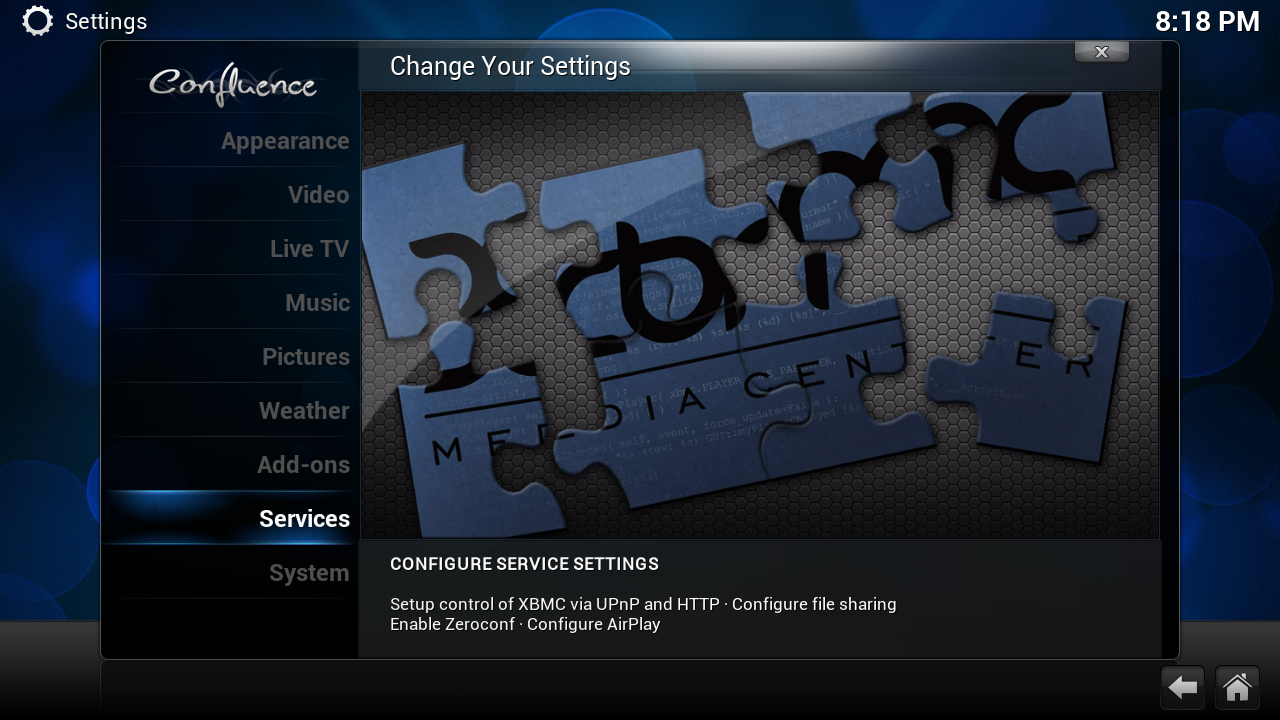
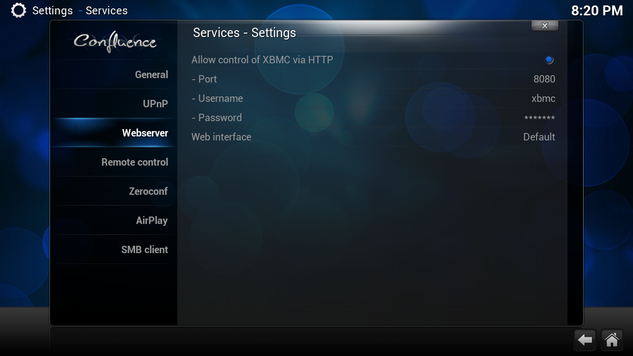
The next step after the layout is to configure the network settings and web server services (for remote control with Android / iOS).
Network Configuration:
Setup (Beginners):
Network Configuration:
Setup (Beginners):
- Navigate to System --> OpenELEC
- Check the Network tab. WIreless Network should be enabled.
- Then go to Connections. Select your wireless network and hit connect. Enter any security pass phrases if any and you should be connected to the wireless.
- A list of wireless networks should show up including yours. If nothing shows up, please check the USB Wifi Adapter and see if it's compatible with the Raspberry Pi. For a list of all compatible Wi-Fi devices, please visit http://elinux.org/RPi_USB_Wi-Fi_Adapters.
- Scroll to the Web Server section.
- Follow Steps 1 through 4 for Beginners
- You need to change the type of IP addressing from DHCP to Manual. This is to easily recognize the Raspberry Pi by IP address.
- Select your wireless network and select Edit.
- Select the IPv4 tab and change the IP Address Method to Manual
- Find your your current Network Settings on a PC / Mac
- PC
- Open up the Command Prompt and enter ipconfig /all
- Make a note of the Subnet Mask and Default Gateway. The Default Gateway is your Wireless Router.
- Log into your router and navigate to the section where it mentions about DHCP server.
- Check the DHCP range and select an IP address that is OUTSIDE of the range for your Raspberry Pi.
- Mac
- Open up the Terminal and enter ifconfig
- Look up the ip address for either eth0 (wired) / eth1 (wireless) and Subnet Mask. Most likely it's 255.255.255.0
- The Default Gateway should end in .1 and the first three numbers should match the first three numbers of eth0 / eth1.
- Like the PC, log into the router, find the DHCP server range and pick one outside the range.
- PC
- Go to Web Server section.
- Navigate to System --> Settings
- Select Services
- Scroll to the Webserver Tab.
- Please enable Allow control of XBMC via HTTP
- Leave the default port at 8080
- You can leave the default Username or change it. Create a password.
XBMC Remote Control
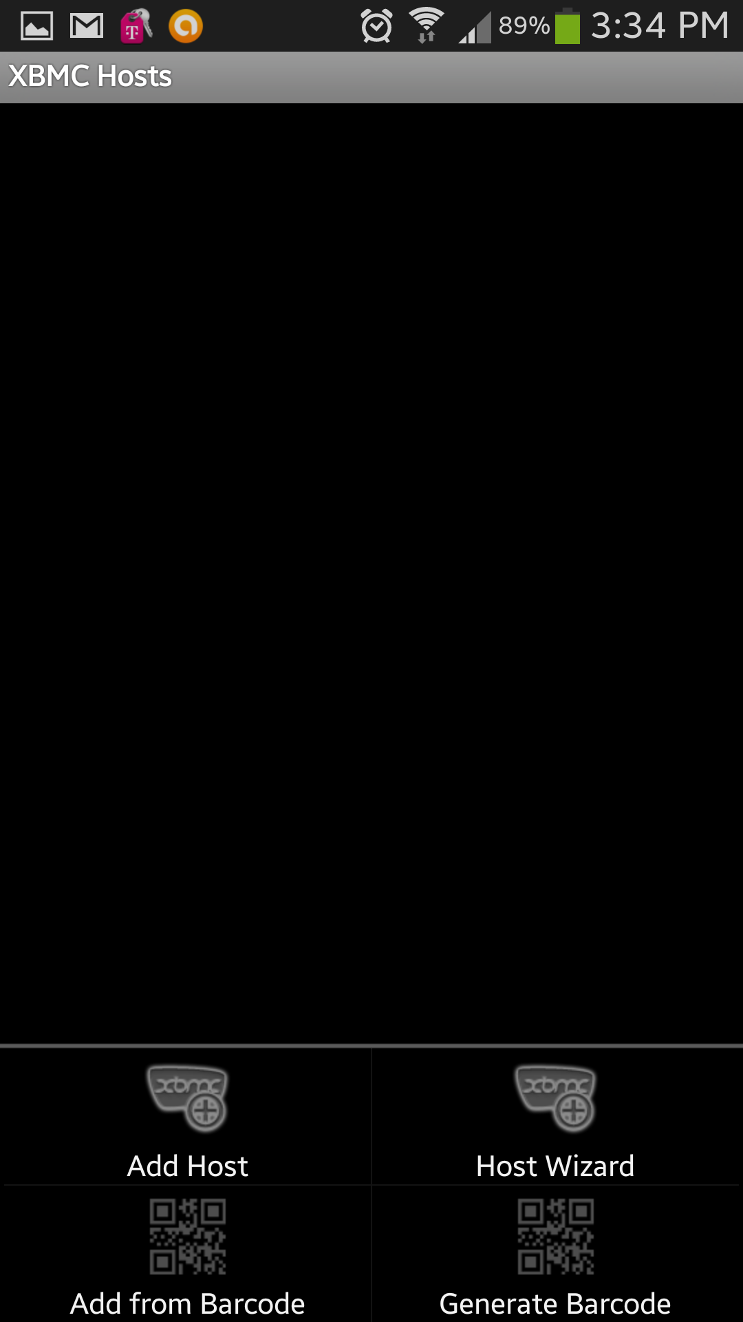
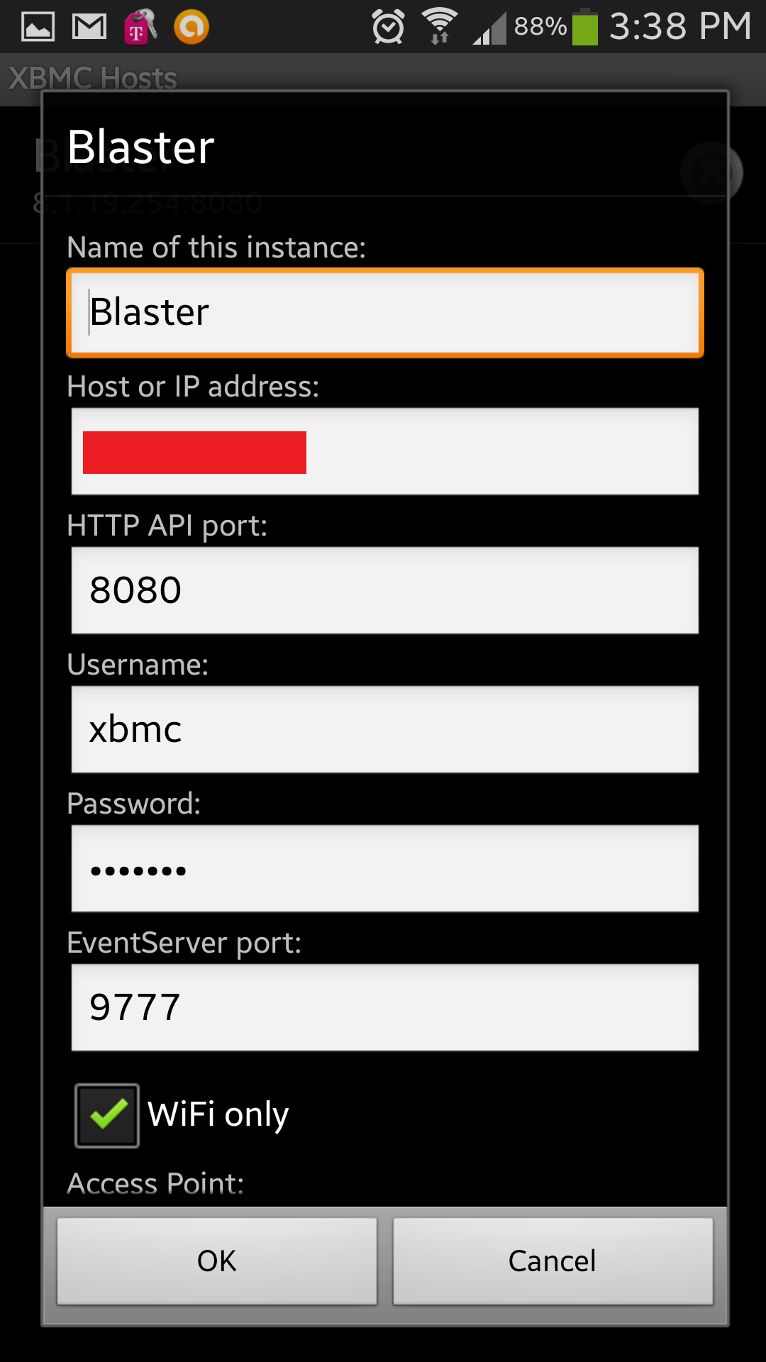
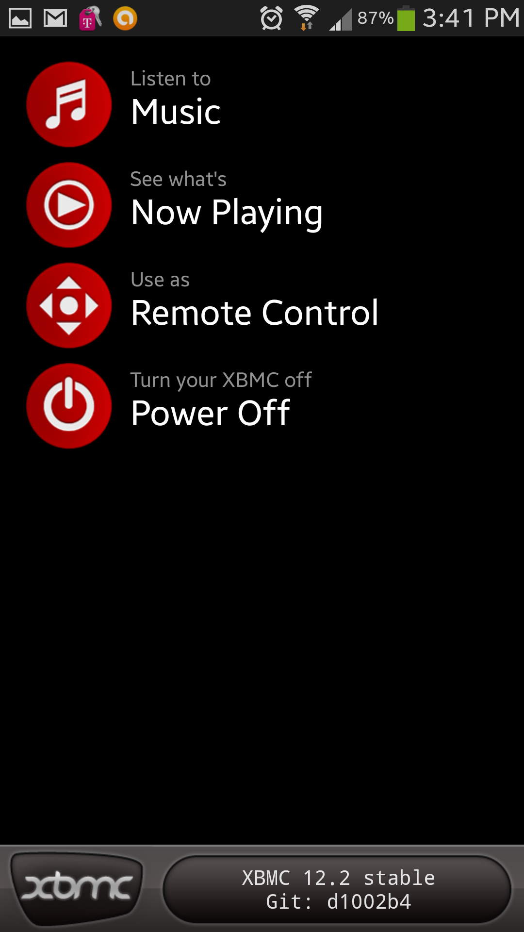
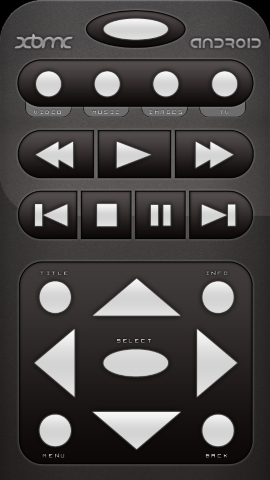
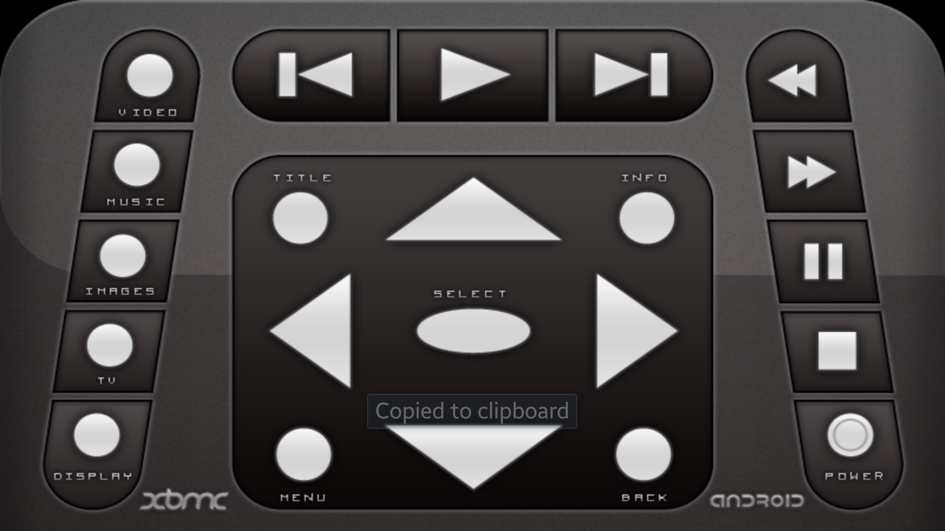
Now it's time to configure the XBMC Remote Control so that you don't have to rely on a USB keyboard to navigate.
XBMC setup:
XBMC setup:
- On an Android / iOS device, download the Official XBMC Remote. I installed it on my Android phone.
- Open the application where is should bring you to the XBMC Hosts.
- If there's no menu option, hit the menu option on your phone to bring up the list of choices.
- Select Add host
- Give a Name for connection
- Enter the IP address of the Raspberry Pi. Refer to the Network configuration section from the previous step. If you used Beginner setup, just navigate to System --> OpenELEC --> Connections. Look for your wireless network, It should display the current IP address.
- The HTTP API port matches the same Port number in the Raspberry Pi Web Server configuration.
- Remember the Username and password you created before in the Raspberry Pi Web Server configuration? Enter that in their respective fields.
- Leave EventServer Port with the default number.
- Select WiFi only and click ok.
- You should now see Use as Remote Control feature.
- Select Remote Control. Look at the Screen where you've connected the Raspberry Pi. Press on the arrow keys on your DEVICE and you should see the selection move. Bingo! You can now disconnect the USB keyboard and use your Android / iOS device.
Lumber
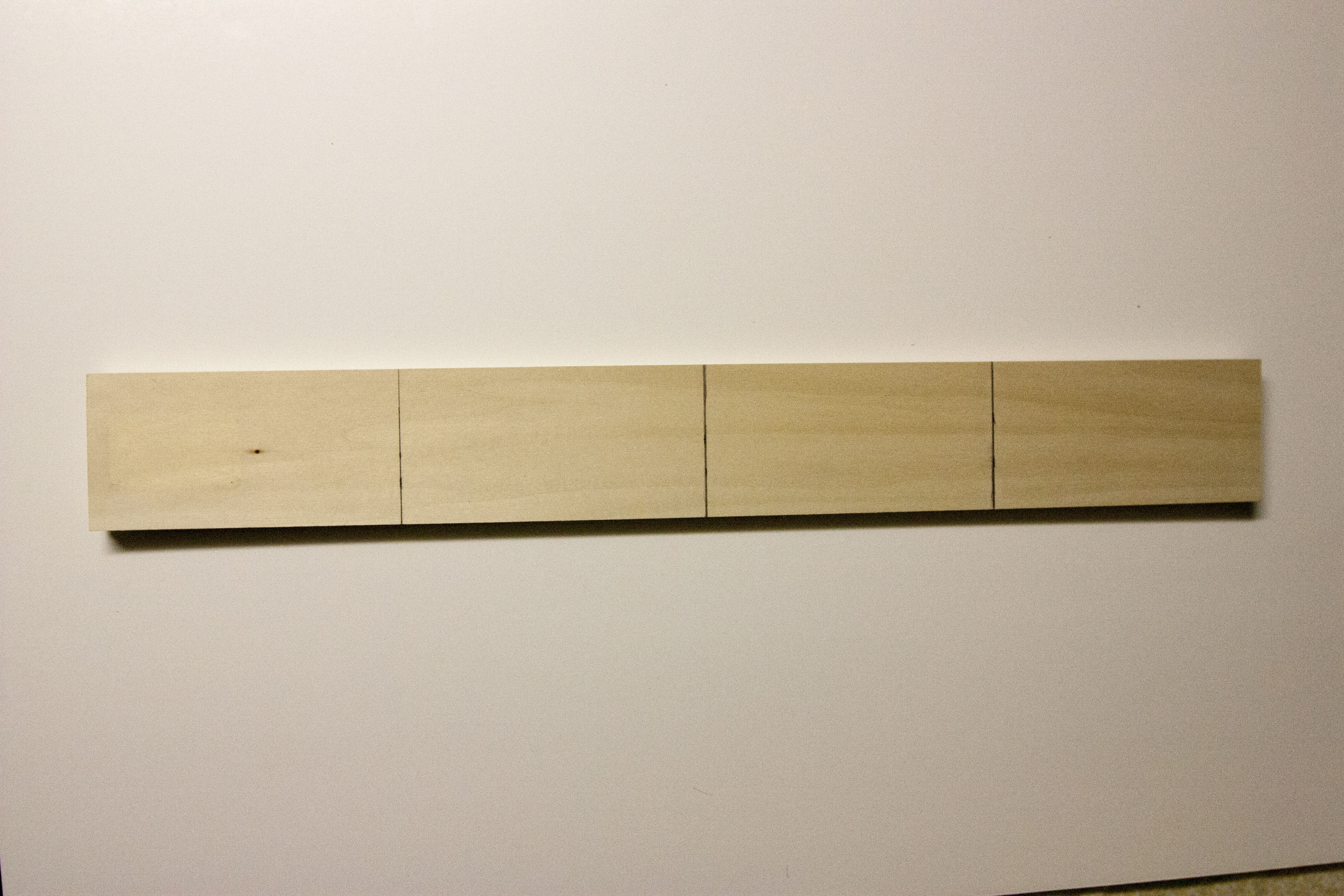
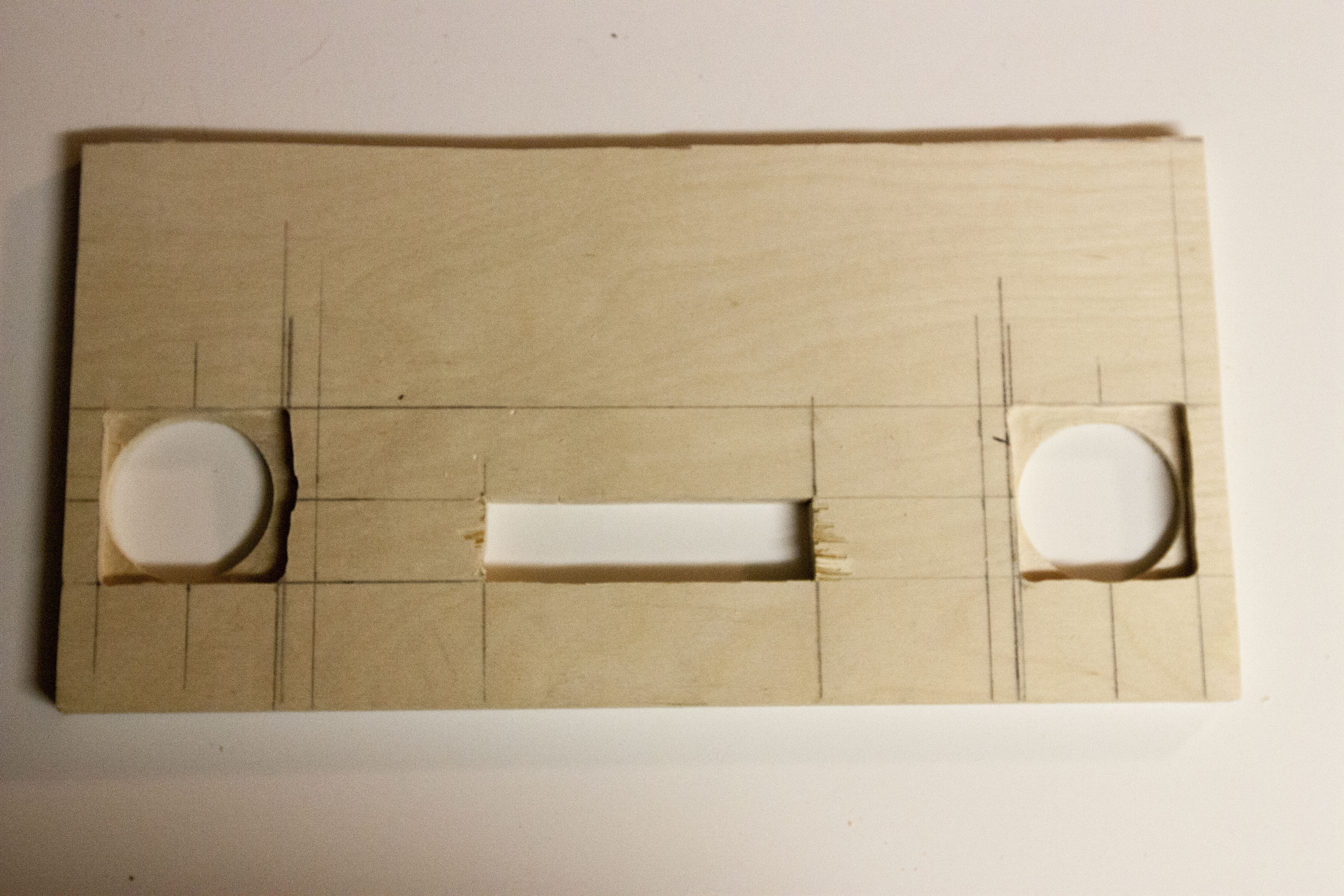
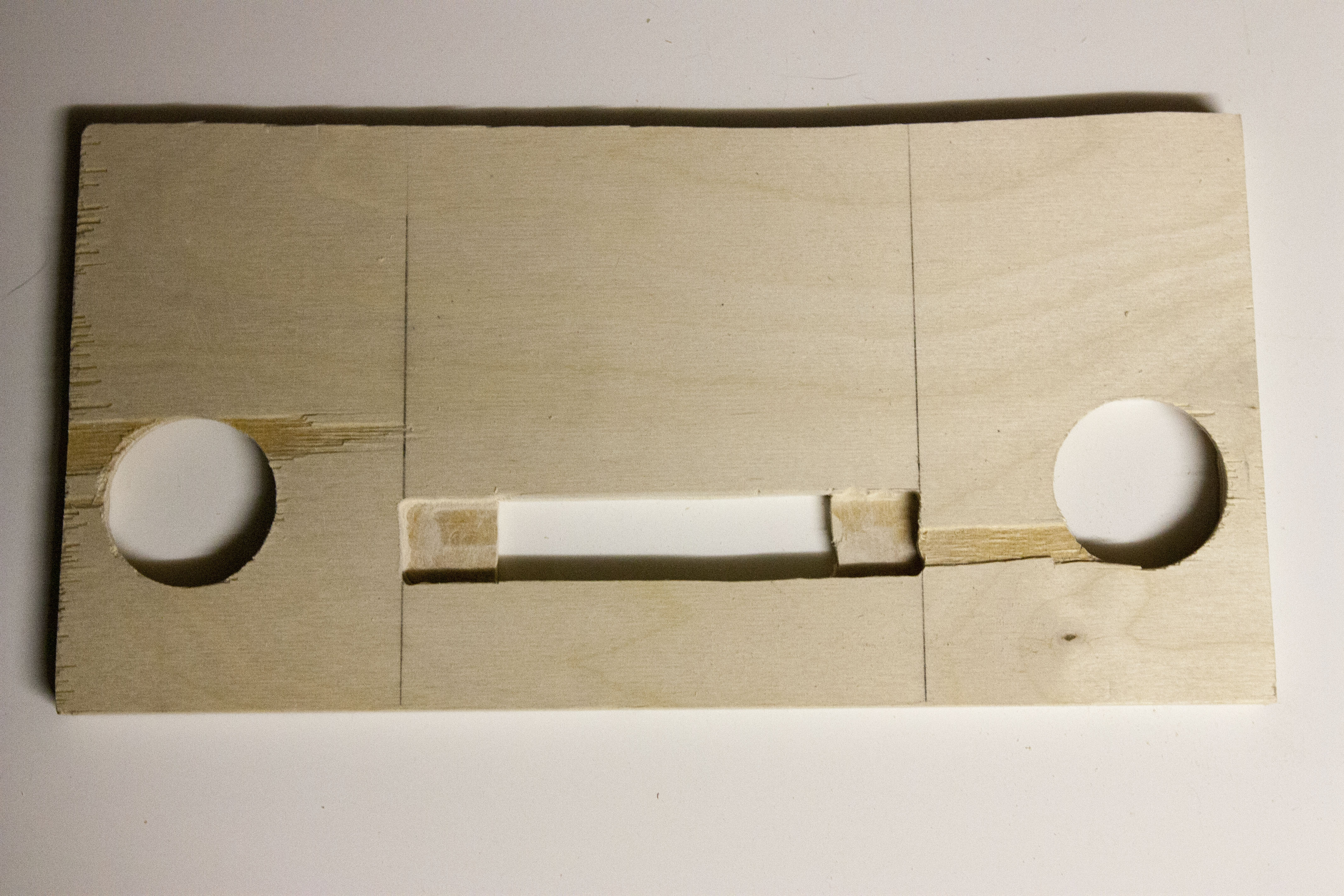
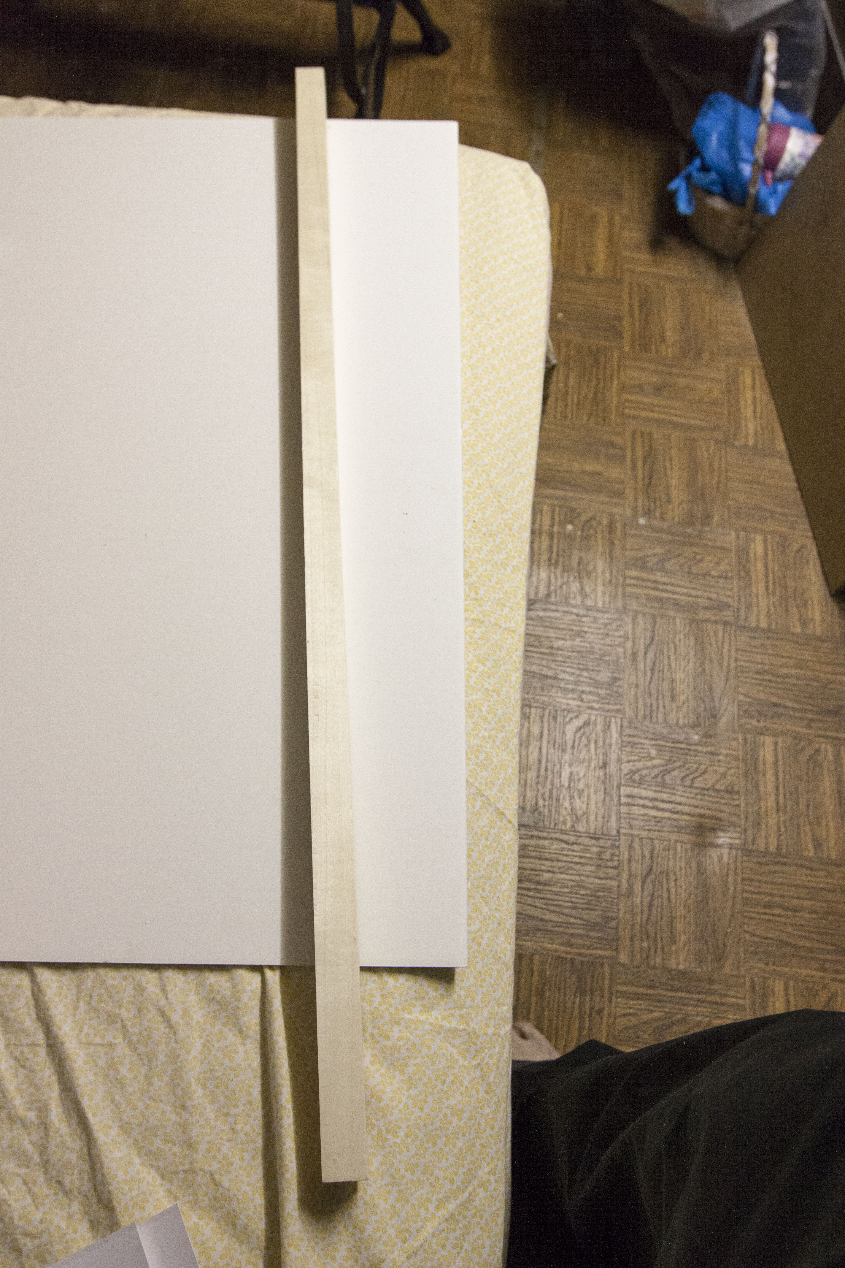
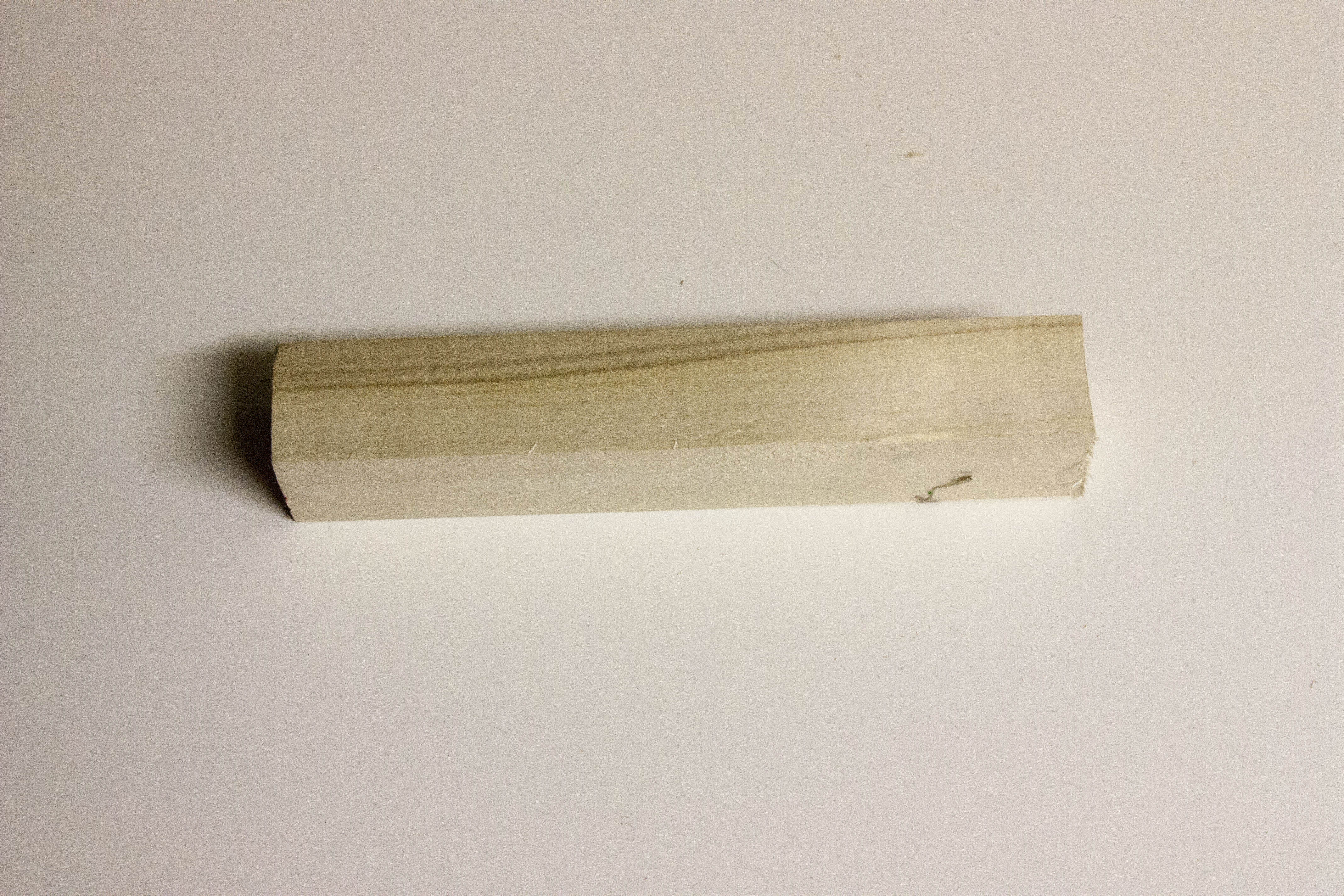
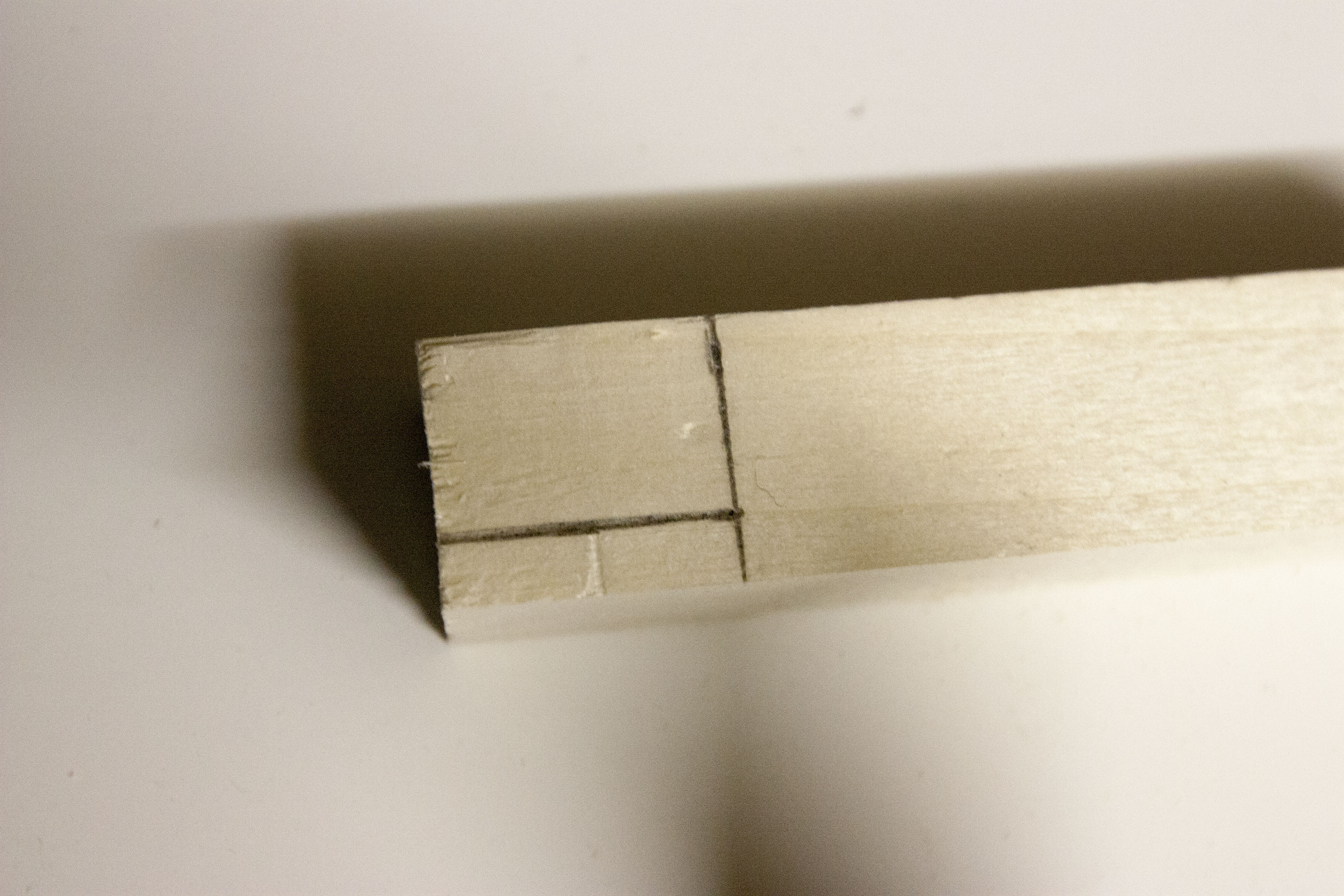
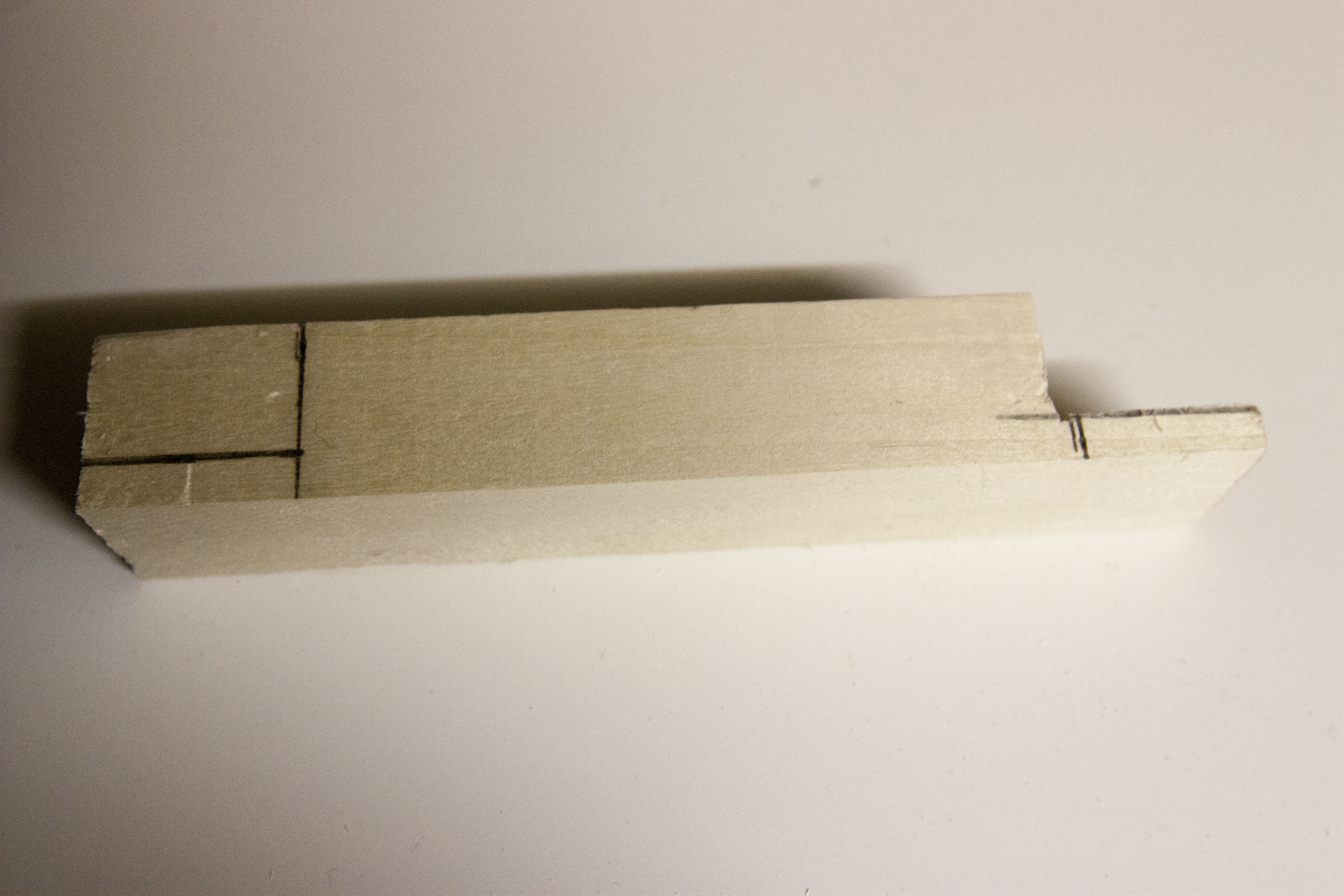
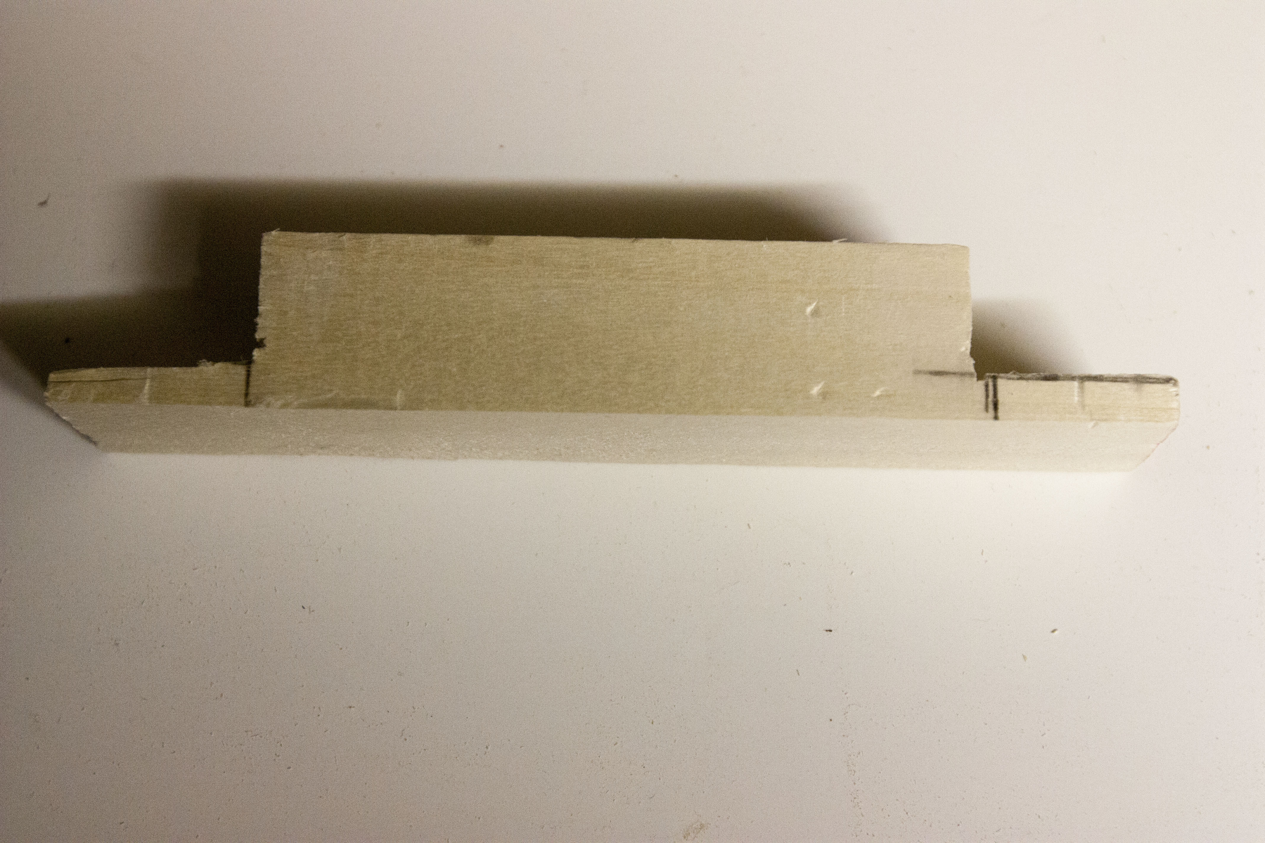
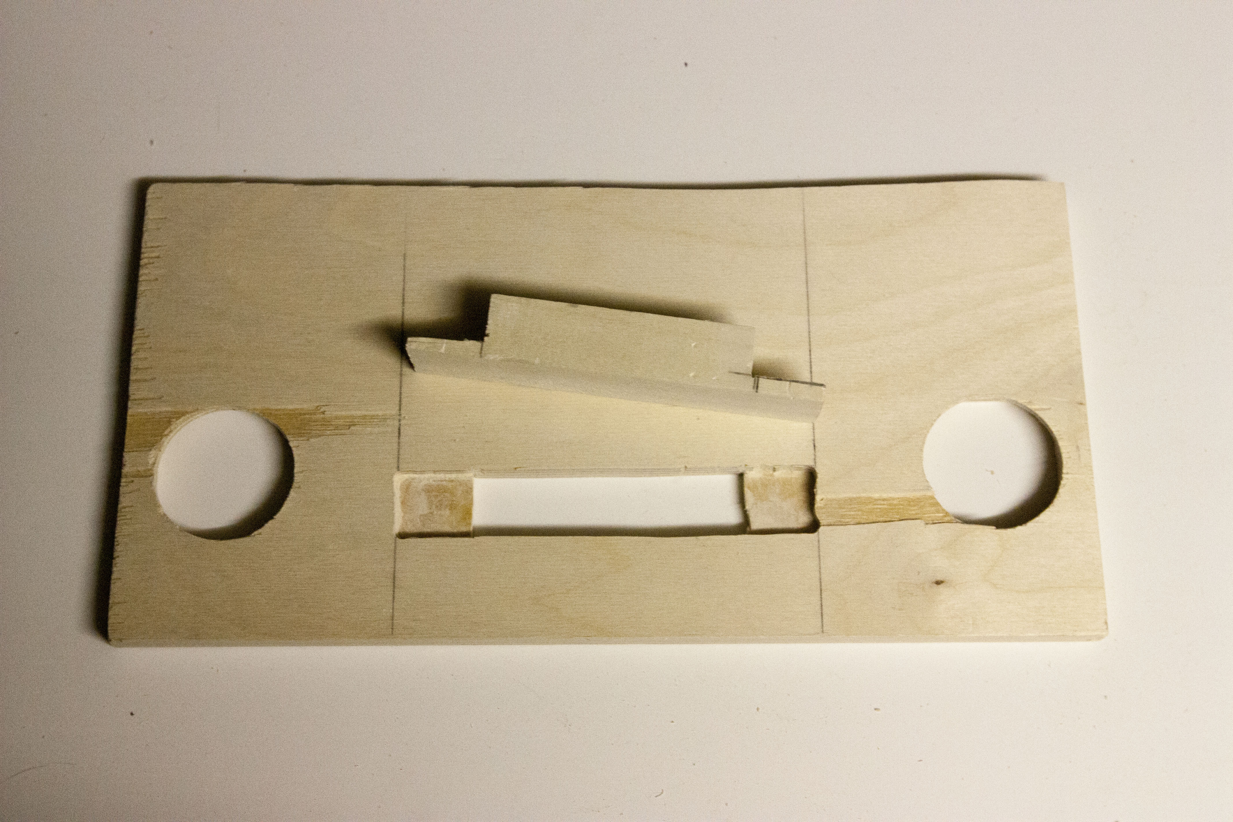
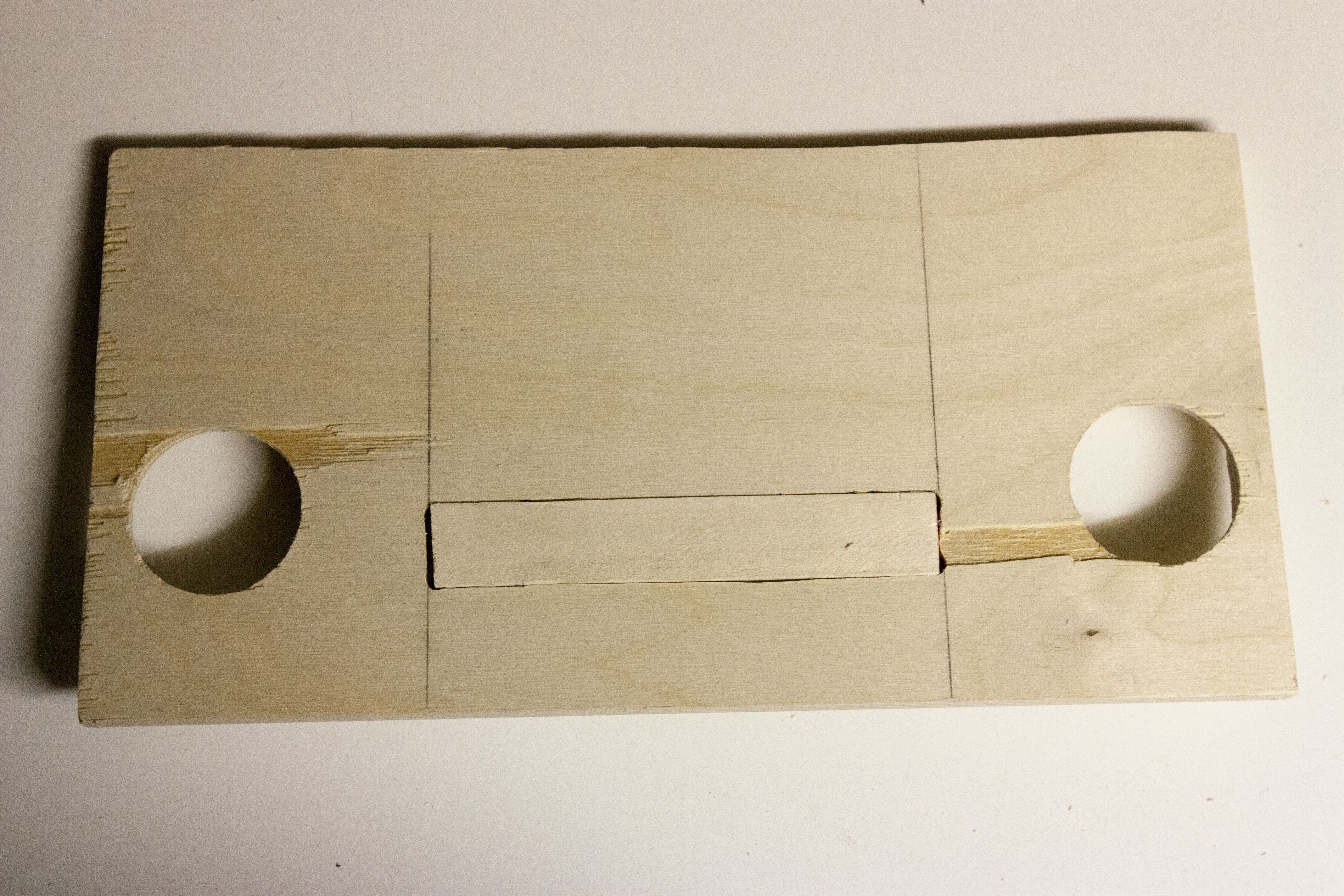
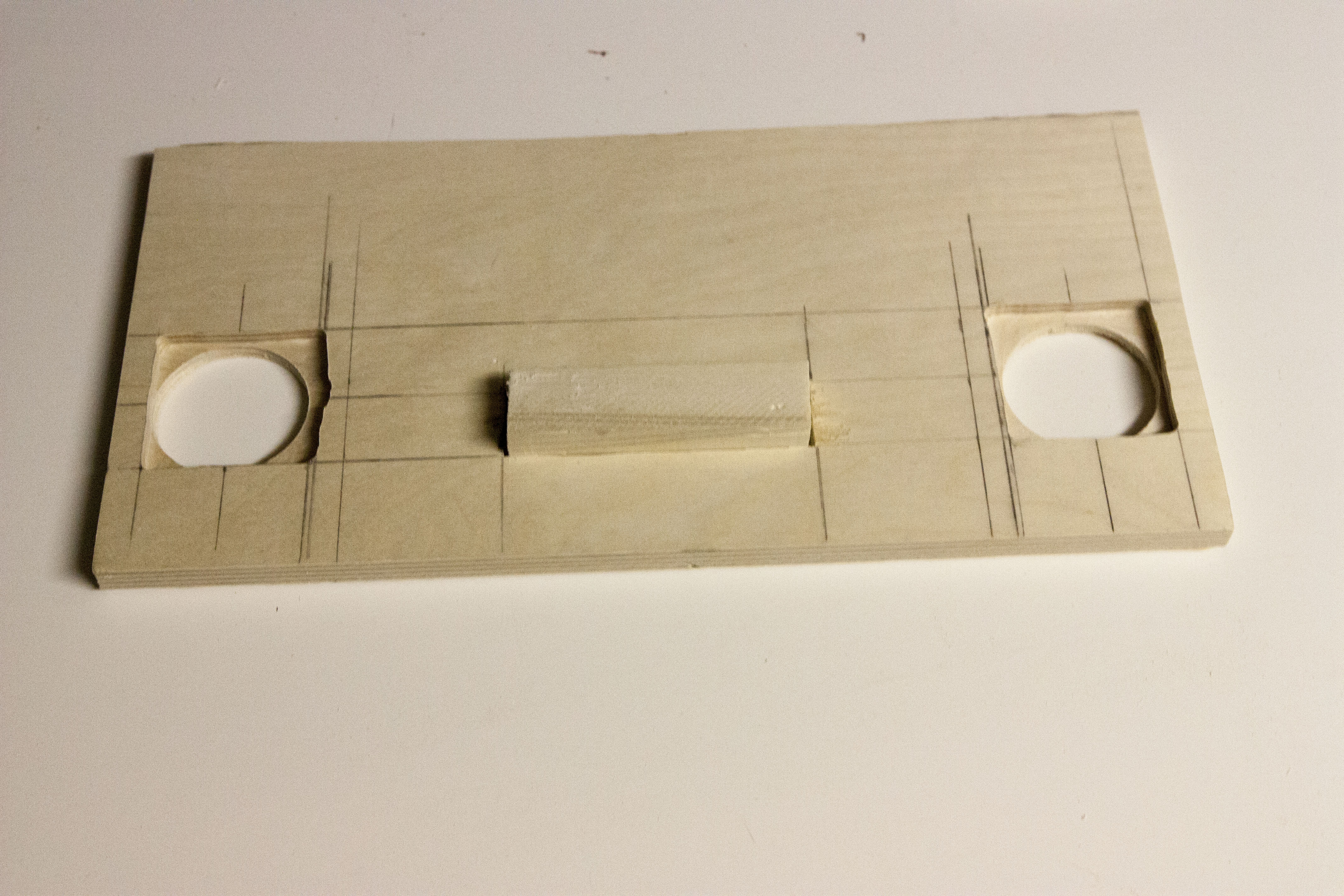
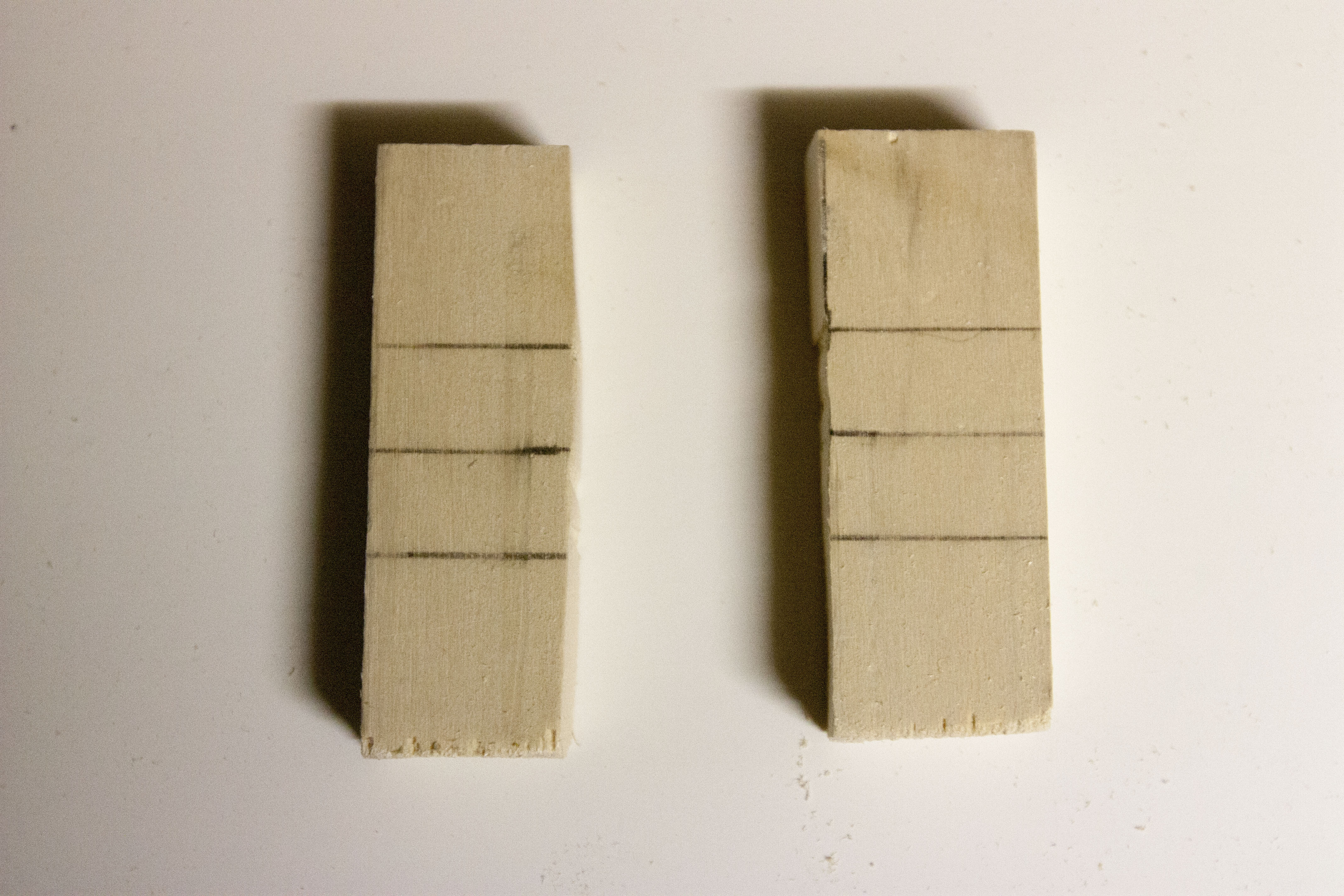
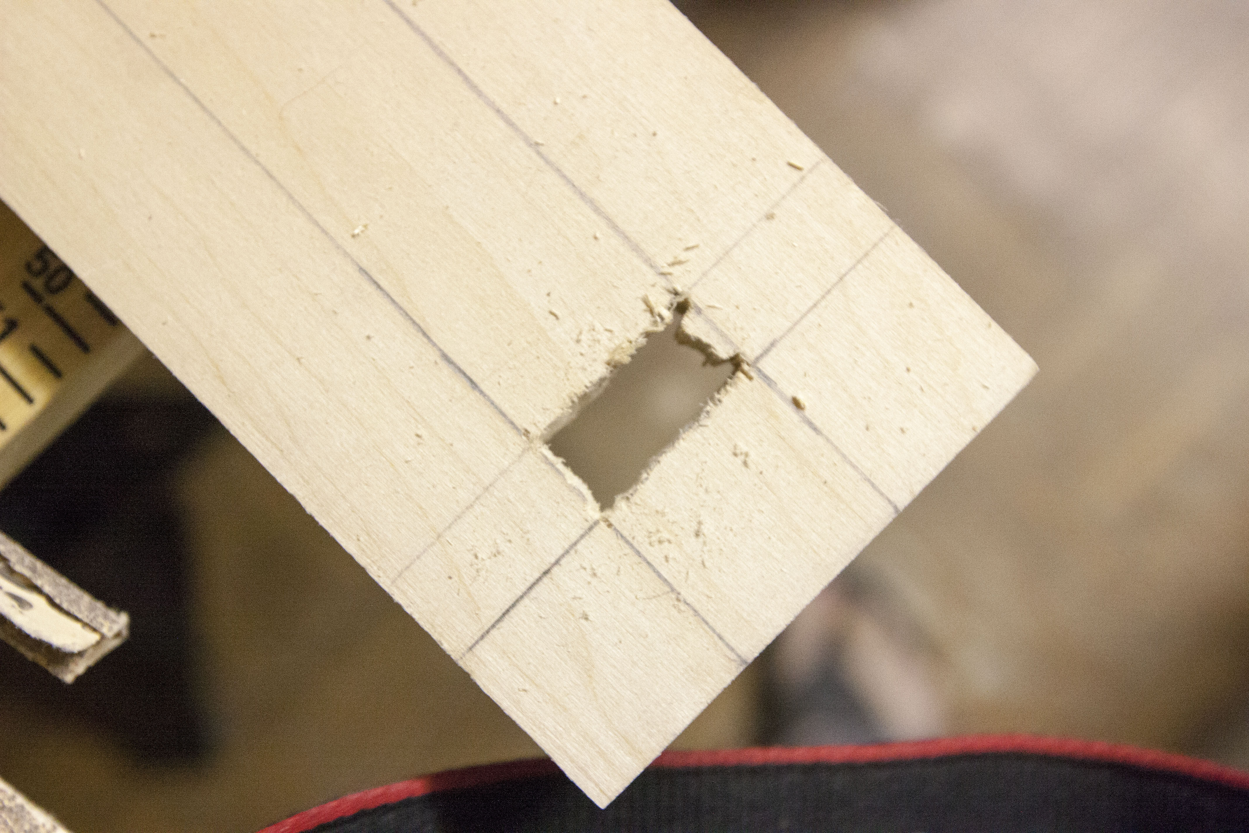
After configuring the Raspberry Pi, it's now time to build the housing unit to hold the parts together.
Lumber
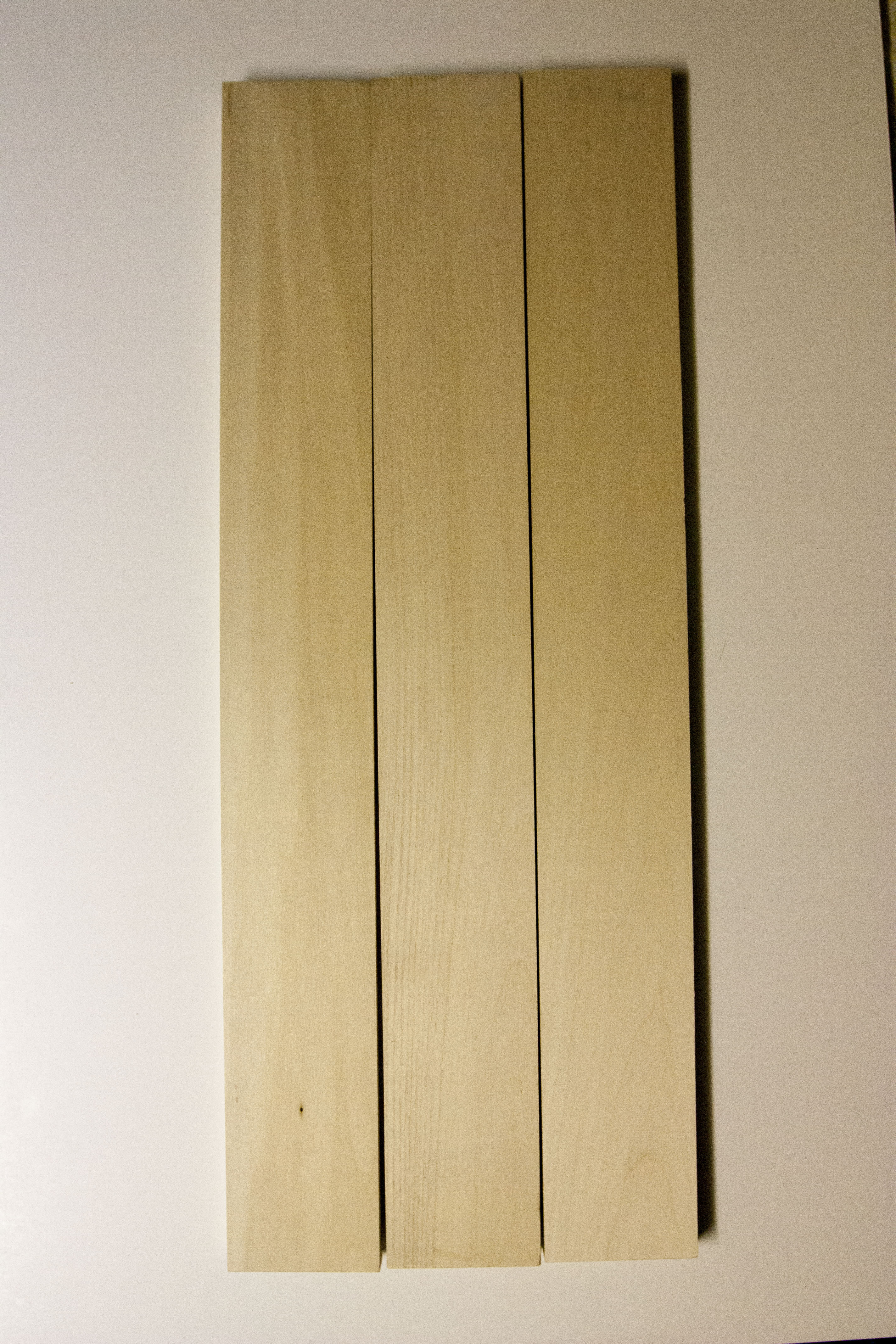
4 - 3" x 24" x 1/2" Basswood board from Dick Blick Art Materials
Note: they sell them in pkg of 5 online. I purchased them individually at $5.84 in stores.
1 - 1" x 36" x 1" dowel from Home Depot
1 - 12" x 24" x 1/8" Birch Veneer Plywood sheet from Utrecht Art
1 - 12" x 24" x 1/2" Birch Veneer Plywood sheet from Utrecht Art
1 - 1/8" sheet of acrylic
For aesthetics
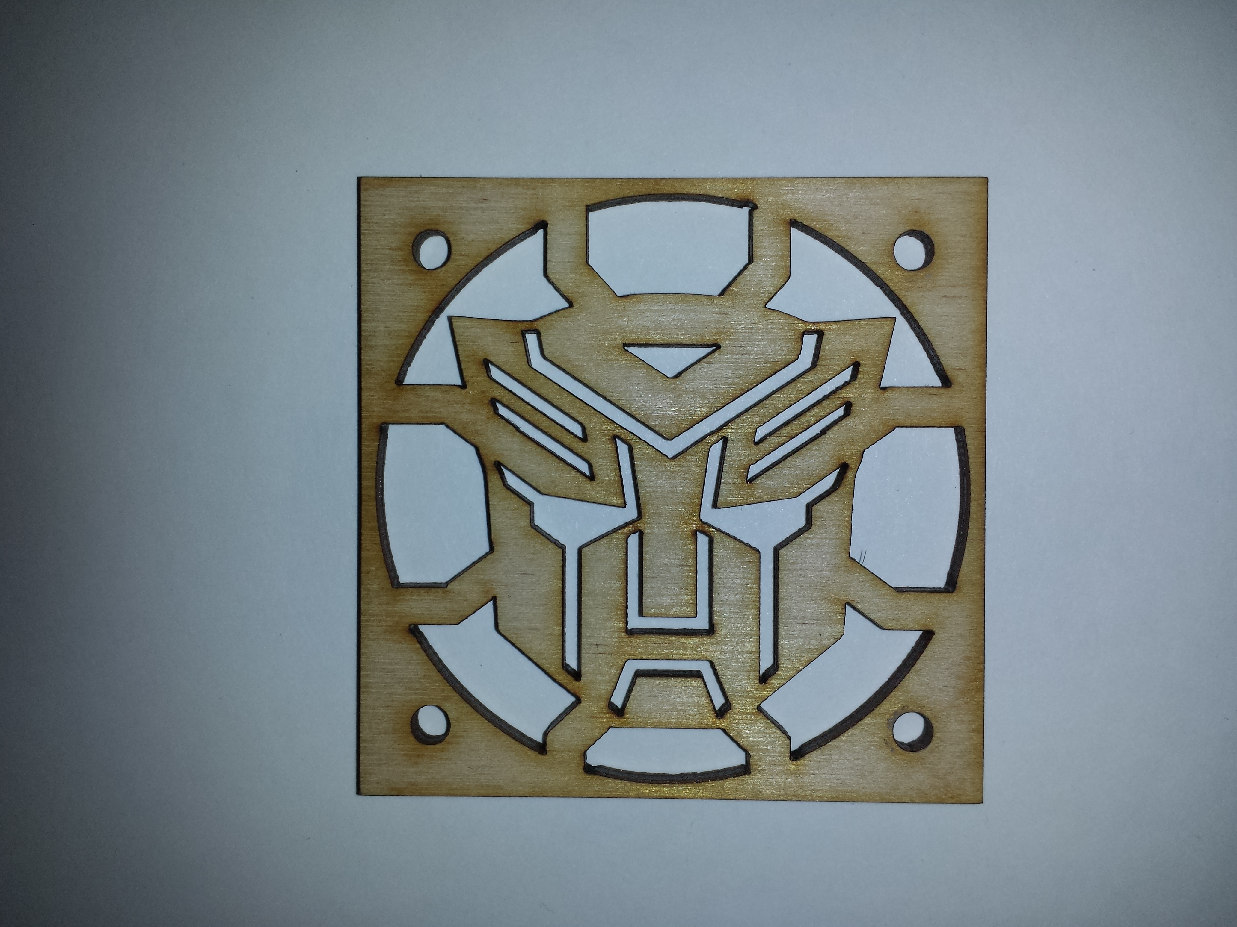
Two custom laser cut speaker covers. Used services from www.Geekifyinc.com
I had four of them laser cut and shipped to me for $35. I requested 2 birch plywood for durability and 2 acrylic.
Measurement of the speaker covers: 2 1/8" L x 2 1/8" W x 1/8" D.
Attached is the Illustrator file so you save yourself creating one yourself :-)
Lumber
7x14 (1/2 inch)
Lumber
4 - 3" x 24" x 1/2" Basswood board from Dick Blick Art Materials
Note: they sell them in pkg of 5 online. I purchased them individually at $5.84 in stores.
1 - 1" x 36" x 1" dowel from Home Depot
1 - 12" x 24" x 1/8" Birch Veneer Plywood sheet from Utrecht Art
1 - 12" x 24" x 1/2" Birch Veneer Plywood sheet from Utrecht Art
1 - 1/8" sheet of acrylic
For aesthetics
Two custom laser cut speaker covers. Used services from www.Geekifyinc.com
I had four of them laser cut and shipped to me for $35. I requested 2 birch plywood for durability and 2 acrylic.
Measurement of the speaker covers: 2 1/8" L x 2 1/8" W x 1/8" D.
Attached is the Illustrator file so you save yourself creating one yourself :-)
Lumber
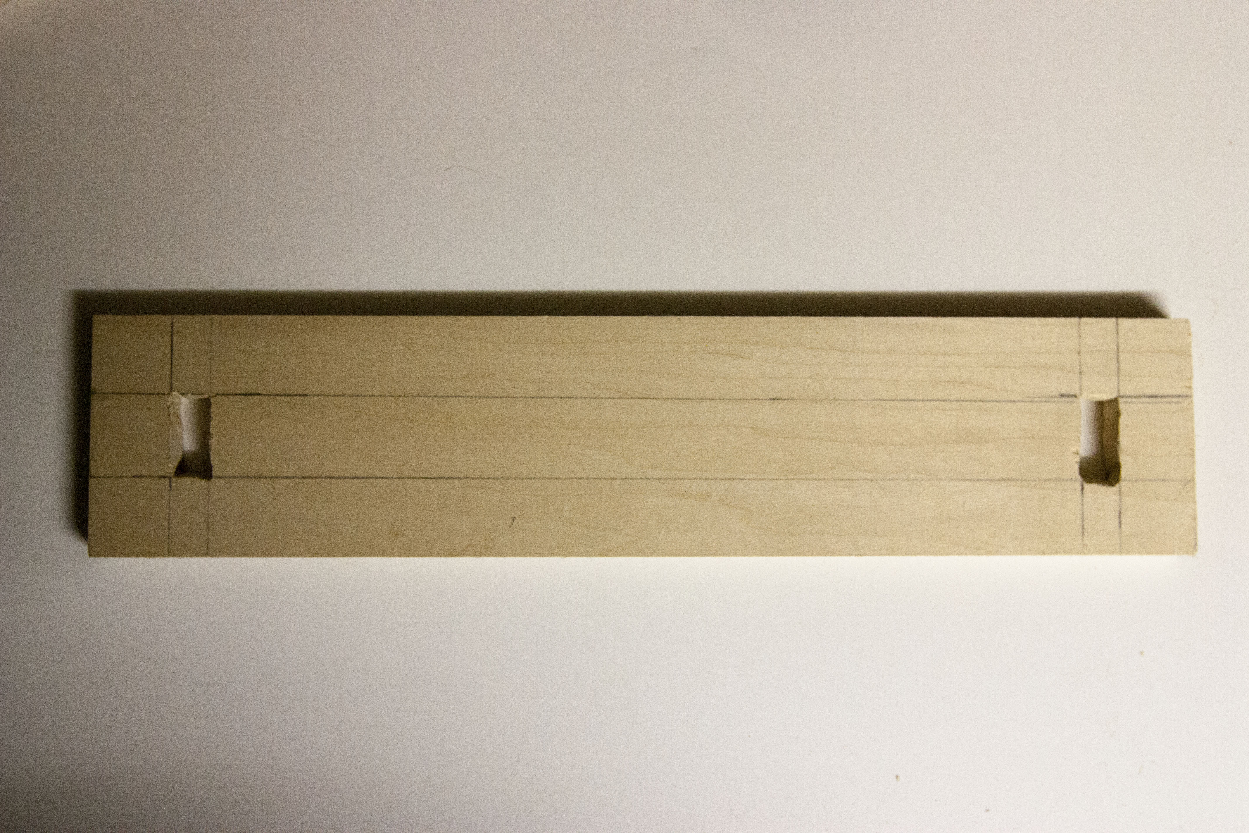
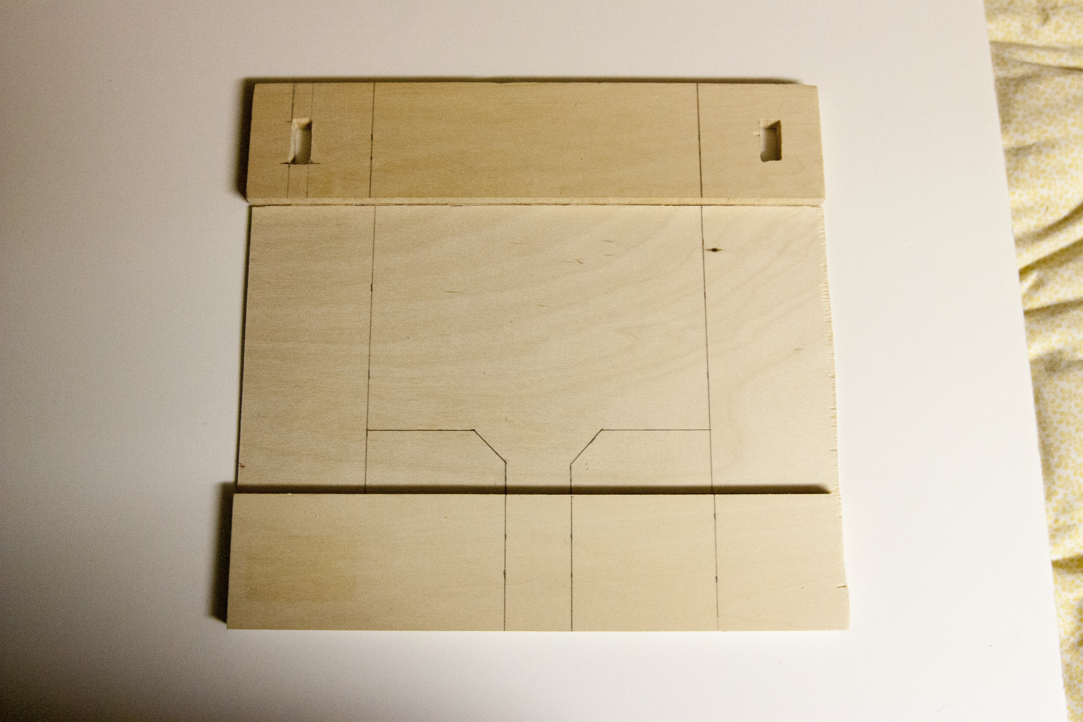
- Take one of the 3x24 boards and cut two 6 inch pieces.
- Use the other two 3x24 boards and cut each board to 14 inches in length.
- With the last 3x24 inch board, cut the board to a 1x12 inch board. That would make the measurement 1/2" x 1" x 12".
- Using the left over pieces of the 3x24 boards, cut two smaller boards with the measurements of 1"W x 3" L x 1/2" D
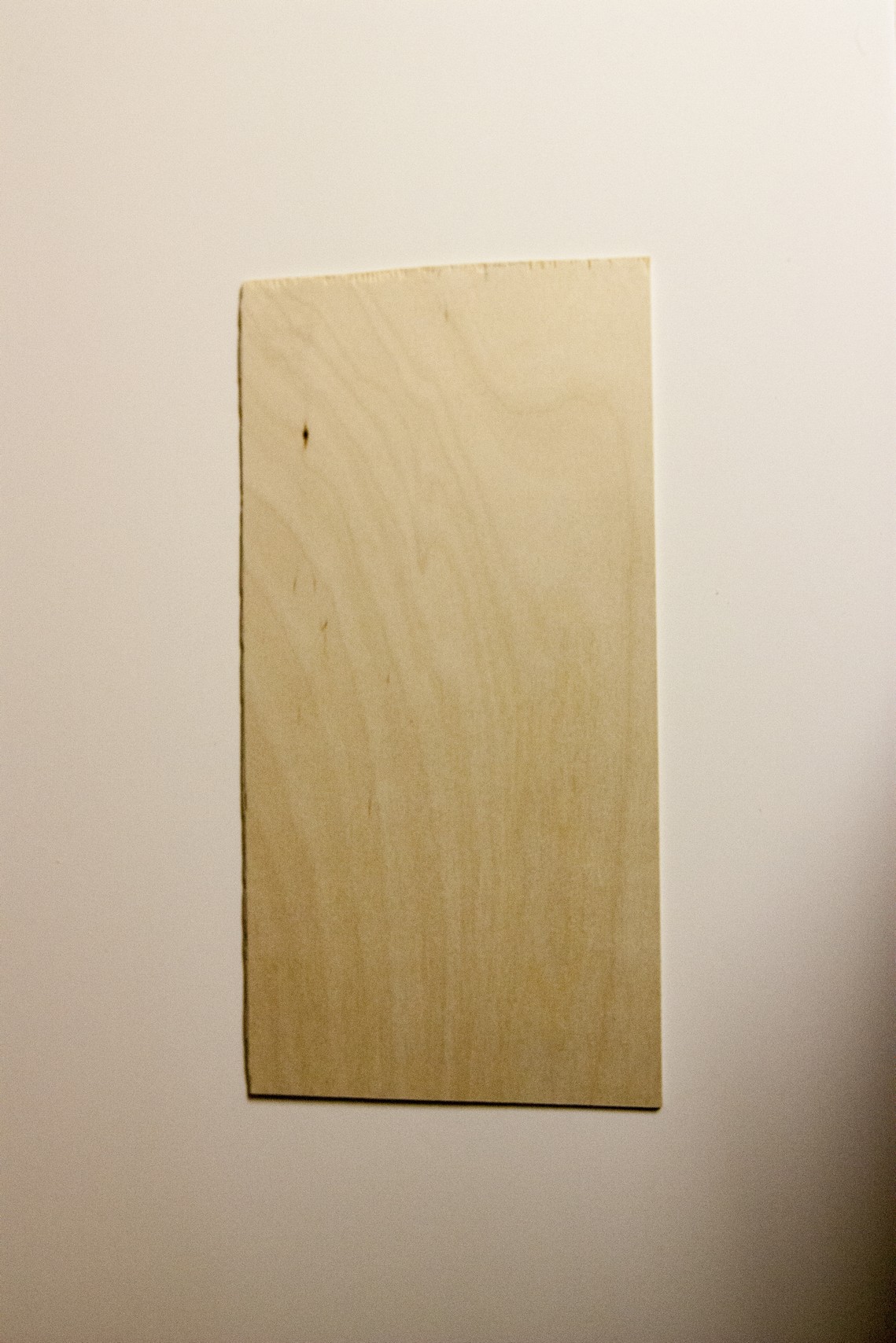
- Cut the 12x24 plywood to 7x14 for both 1/2 inch and 1/8 inch boards
- Make a vertical line 3 inches from the left and right border.
- Draw a 2 1/2 inch line 1,5 inch from the bottom starting at 3 inches from the left. Repeat on the right side.
- Draw a 3/4 inch vertical line 3 1/4 inches starting at 3 inches from the left. Again repeat on the right side.
- Connected the endpoints of the 2 1/2 inch line and the 3/4 inch line.
- This will be the guidelines for painting.
7x14 (1/2 inch)
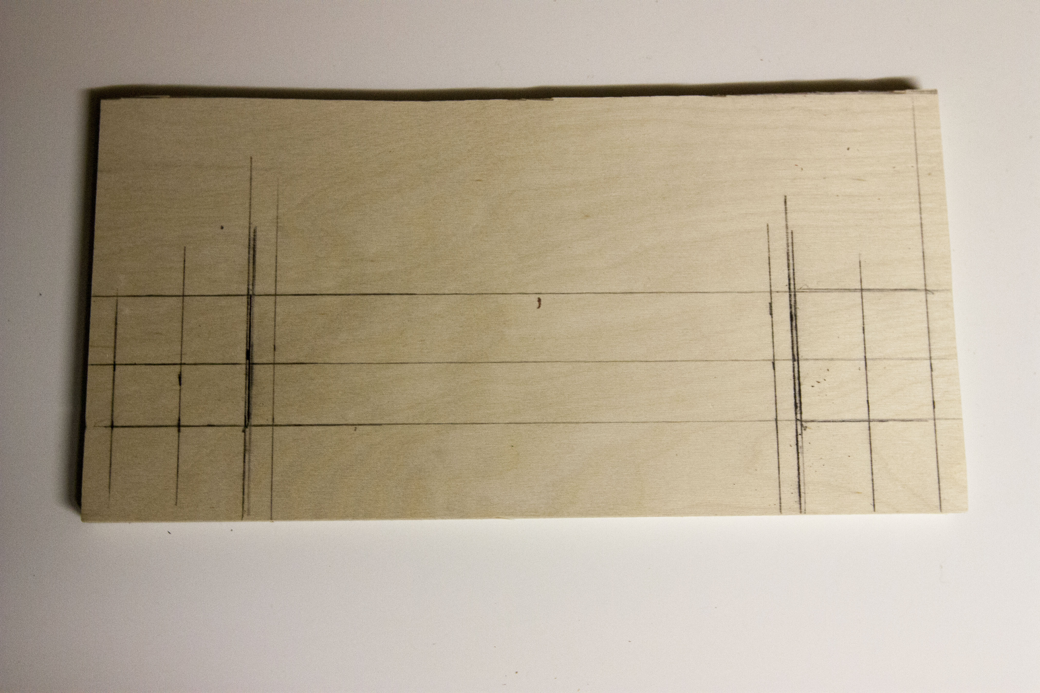
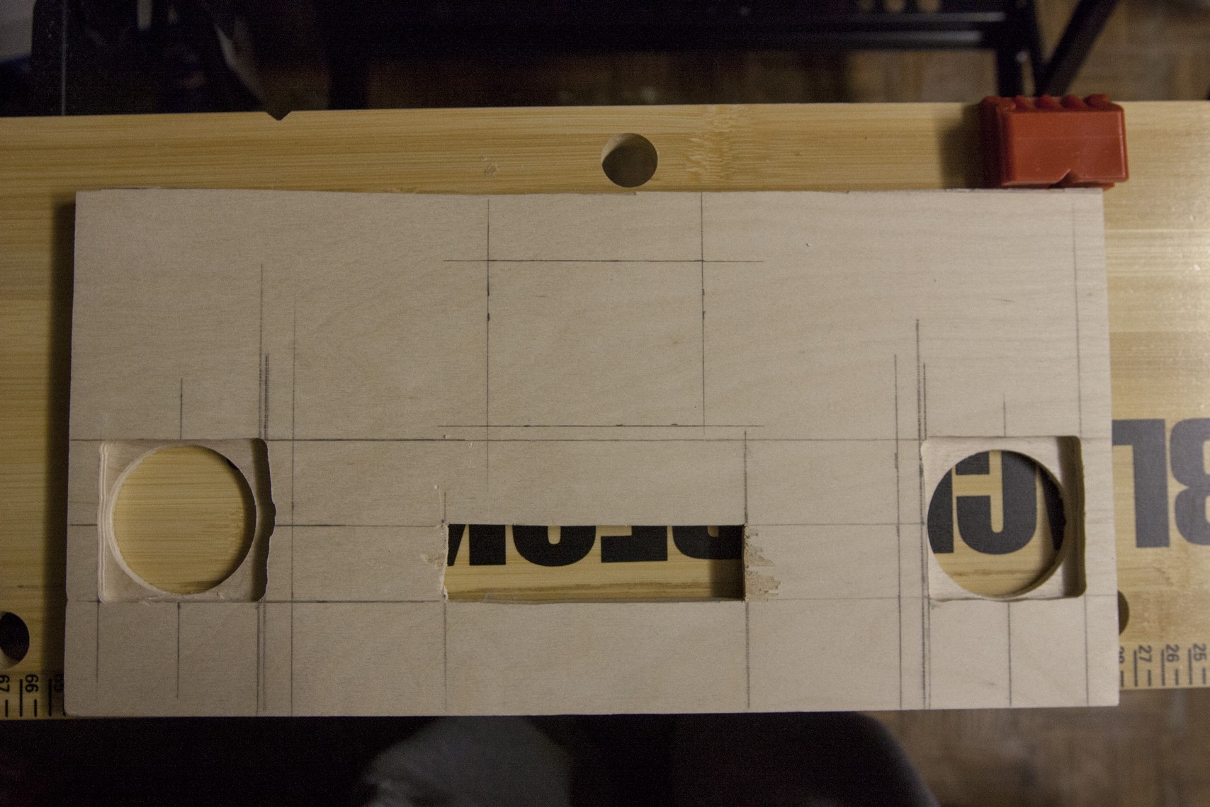
- Draw a line at 3 inches and 11 inches
- Draw another line at 1.5 inches and 12.5 inches (this is the center point where you're going to drill)
- Measure 1.5 inches from the bottom and 7/16 inch from the sides and draw a 2 1/8" line both horizontally and vertically.
- Draw a 2 1/8 inch vertical line from the left of the 3 inch mark and right of the 11 inch mark. Make sure you have a 7/16 space from the left of the 3 inch mark and 11 inch mark.
- Connect the 2 1/8 inch vertical lines together and you should now have a 2 1/8 x 2 1/8 inch square.
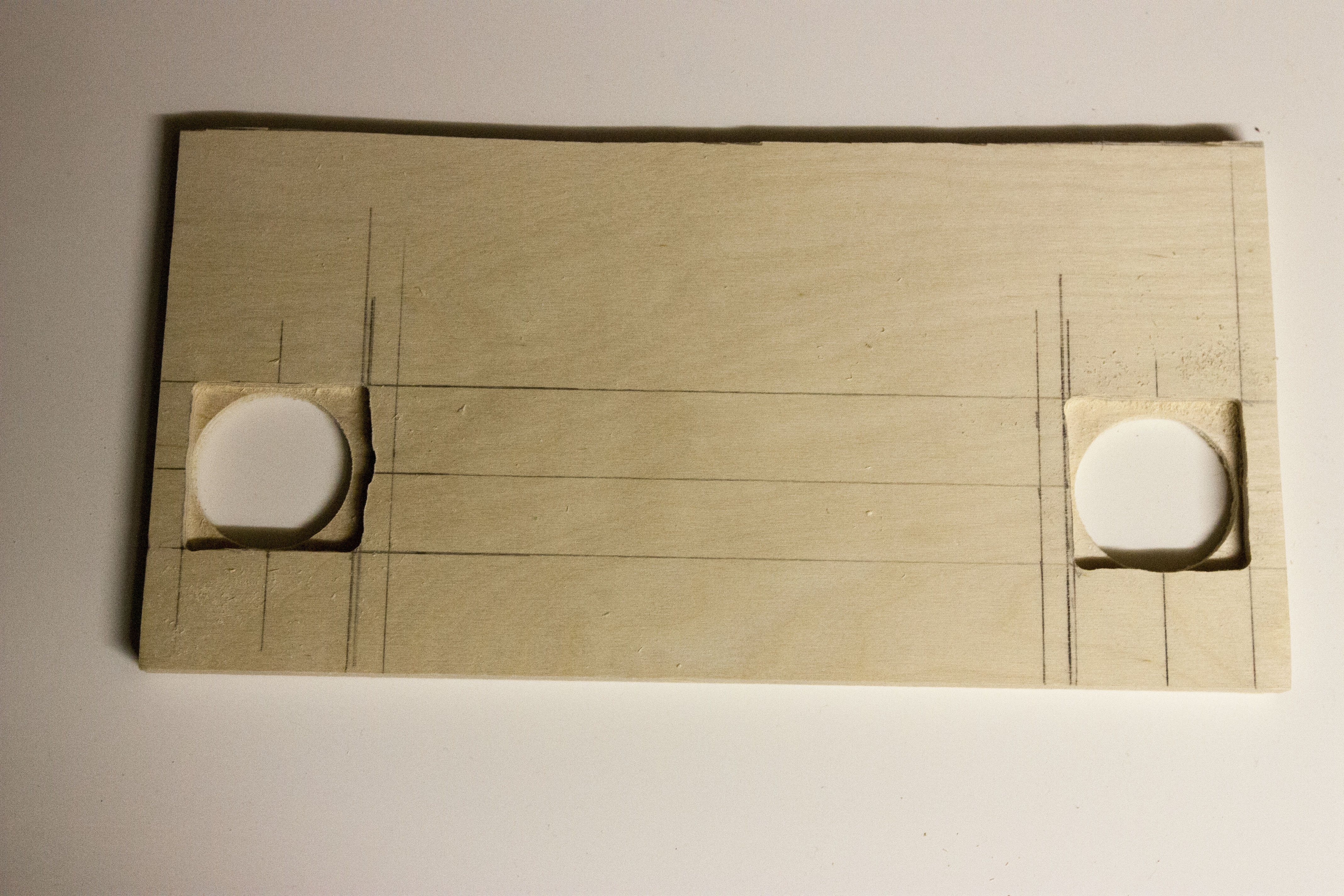
- Use a 2 inch hole saw or spade bit and drill a hole at the center point of the square made (1.5 inches is the center point)
- Using a router, set it at 1/4 inch deep and route the entire square. This should leave a 1/4 inch deep groove for the speakers.
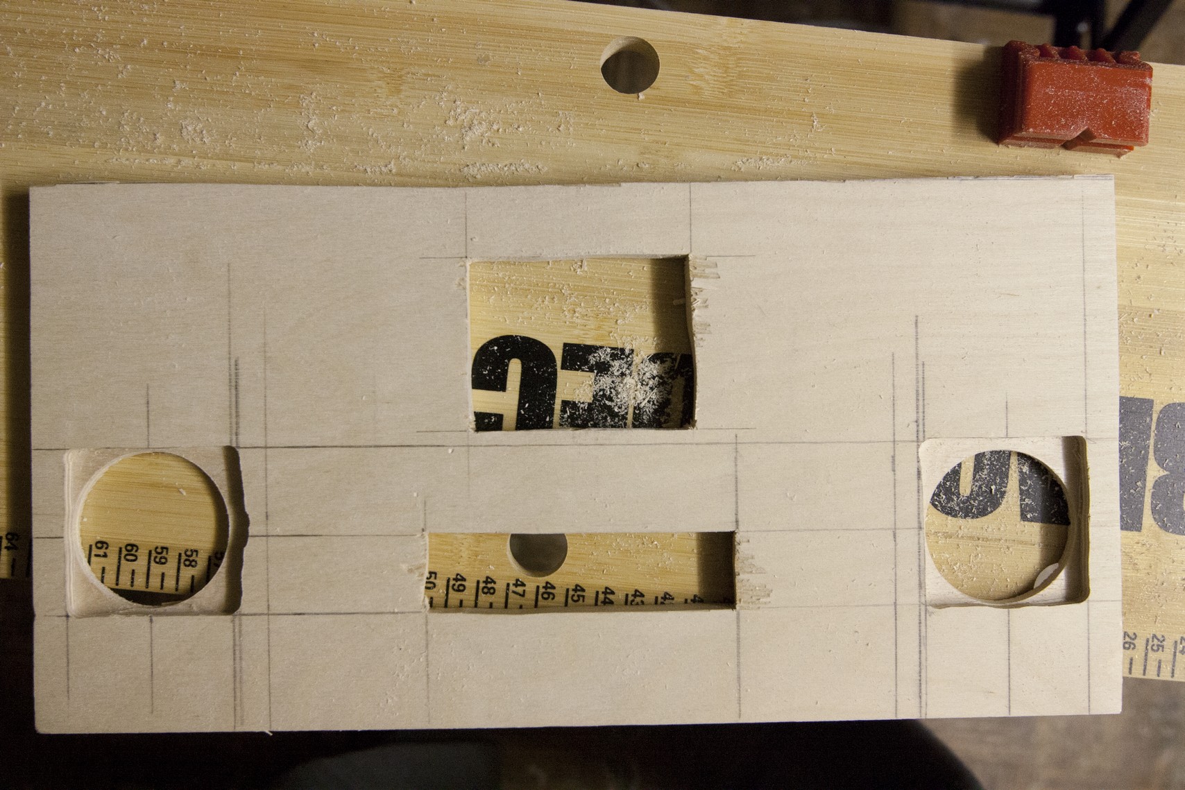
- Draw a line at the 5 and 10 inch point. Make a line from the 5 inch mark to the 10 inch mark. This line should be 1.5 inch from the bottom and should be aligned with the squares.
- Cut a 4 inch by 1 inch rectangle from the 5 inch and 10 inch mark. This should be the FRONT SIDE.
- Flip the now 7x14 board over. Draw a line at the 4 and 11 inch point.
- From the 4x1 rectangle, Draw a 1 inch line to the left and right of the rectangle. You should have a 6x1 rectangle now.
- Using a router, route a 1/4 inch deep. You should now have two 1/4 inch deep squares along with a 4x1 rectangle.
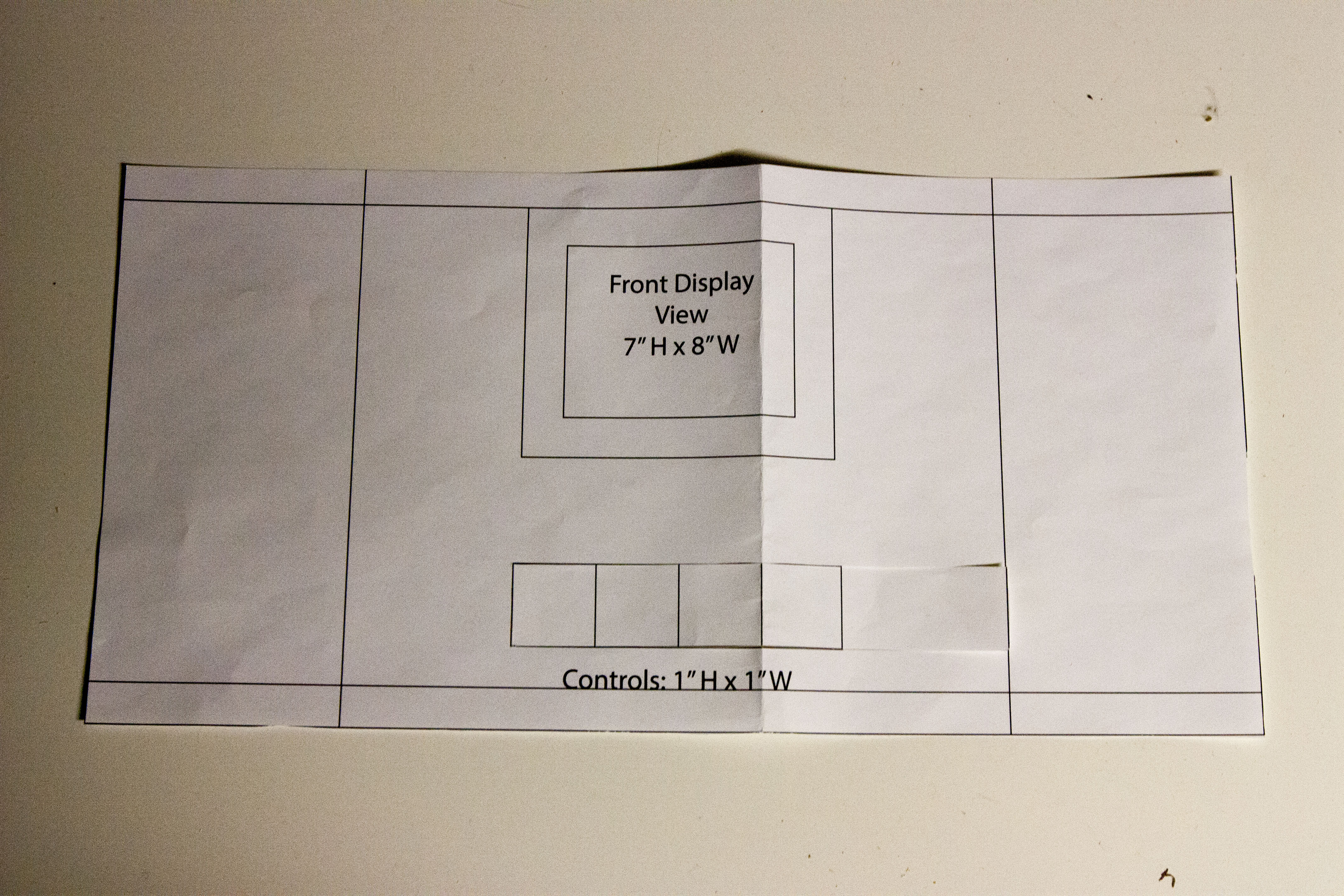
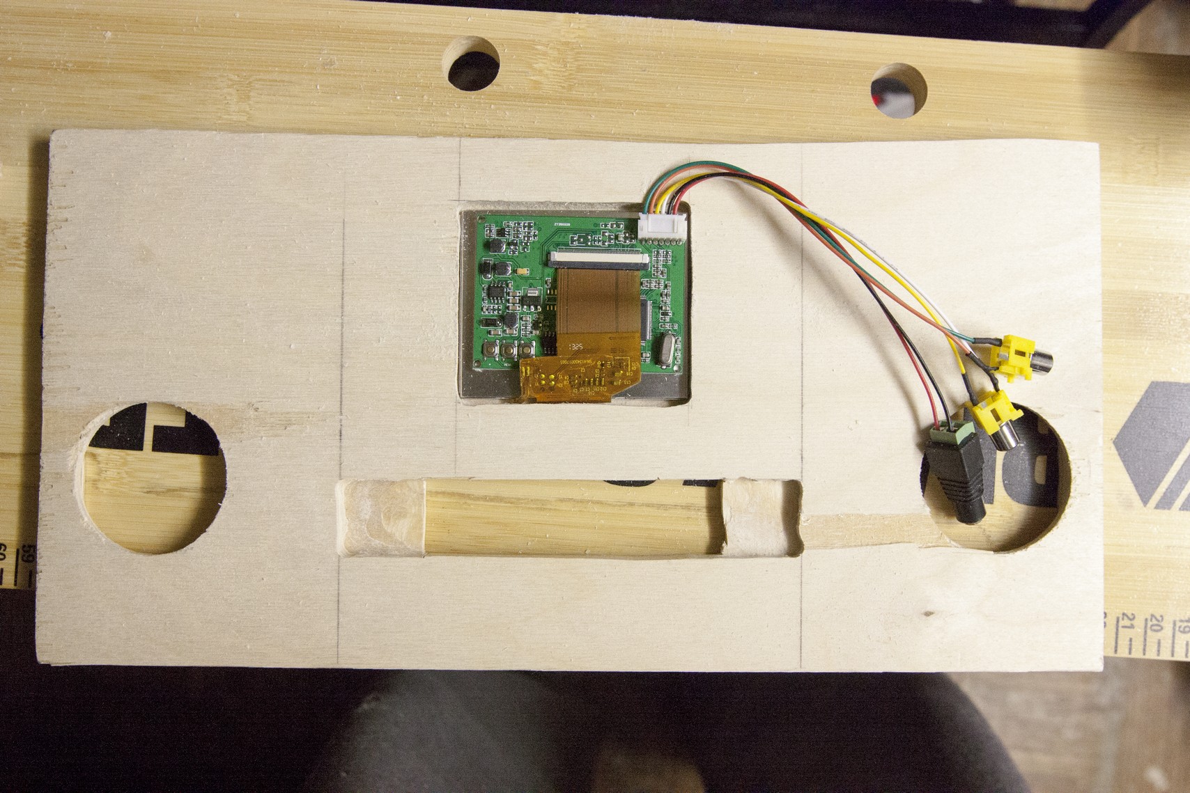
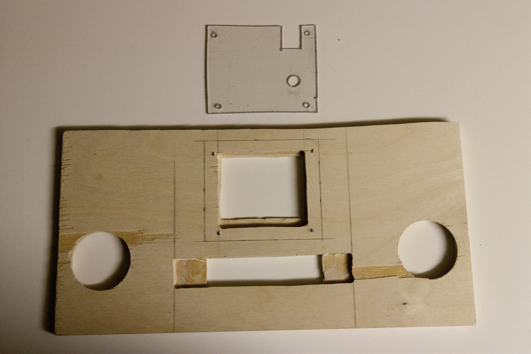
- Measure 5 9/16" from the left and 1" from the top. Cut a box that is 2 7/8" wide by 2 1/4" tall. Once completed, turn to the back side.
- Draw a box that is 3 inches wide and 2 5/8 inch tall with a margin of 5 1/2 inch from the left and 7/8" from the top.
- Route 3/8 inch deep all around for the 2 5/8 inch by 3 inch box you just created. Note: This is for the LCD screen.
- Cut it to 6 inches so it's 1"x1"x6"
- Make a line at the 1 inch point from each side.
- Make another line 1/4 inch from the bottom
- Either cut or route the 1" x 3/4".
- The cut dowel should now fit into the 4x1 rectangle and should protrude 3/4 inch from the front side.
- On the left portion of the 1x12, cut a 1/2 x 1 inch rectangle with a margin of 1 inch from the top and left side.
- Repeat that on the right side.
- Make 3 lines:
- 1st line at 1 inch
- 2nd line at 1 1/2 inch
- 3rd line at 2 inch
- Insert the 1x3 board into the 1/2 x 1 inch hole you just cut on the 1x12 board.
- The 1x3 board should go all the way down to the 2 inch line so that it protrude 1 1/2 inch from the bottom and 1 inch from the top of the 3x14 board.
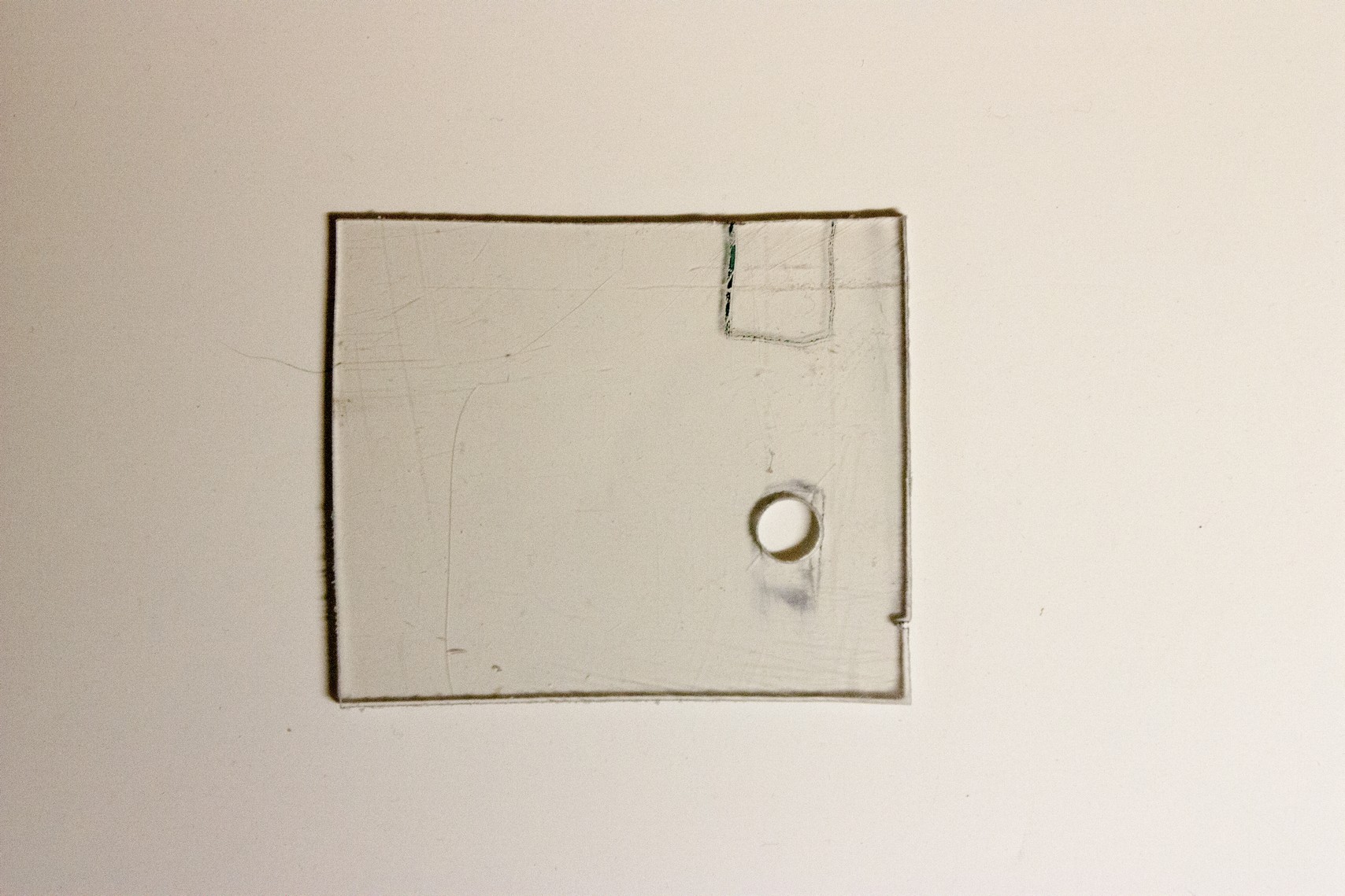
- Cut a 3 7/8 inch by 4 inch box from the acrylic sheet.
- Place the LCD screen inside the 2 5/8 inch x 3 inch box you just completed.
- Place the 3 7/8 inch x 4 inch acrylic over on top of the LCD screen circuit board. Notice how it is not leveled. Using a marker, draw on the acrylic sheet where the power source / video source on the top right and the capacitor that's near the middle / bottom right.
- Use a 7/16 inch spade bit or hole saw and cut a hole where the capacitor is located.
- Use a jigsaw to cut two vertical lines for the power source location. To cut the horizontal line, I used a acrylic sheet scorer and scored the area a few times until I can break off the small piece of acrylic with ease.
- Now place the acrylic sheet over the LCD circuit board. it should be leveled now. with about a 1/16 inch gap.
- Drill four holes so you can lock the acrylic sheet in with screws. I've used #8 3/8" screws so I need to drill four 11/16" holes to accommodate the #8 screws.
- Note the locations of the holes you created on the acrylic. Align the acrylic sheet and drill 1/8 inch holes according the locations on the acrylic sheet.
Downloads
Electronics / Wiring
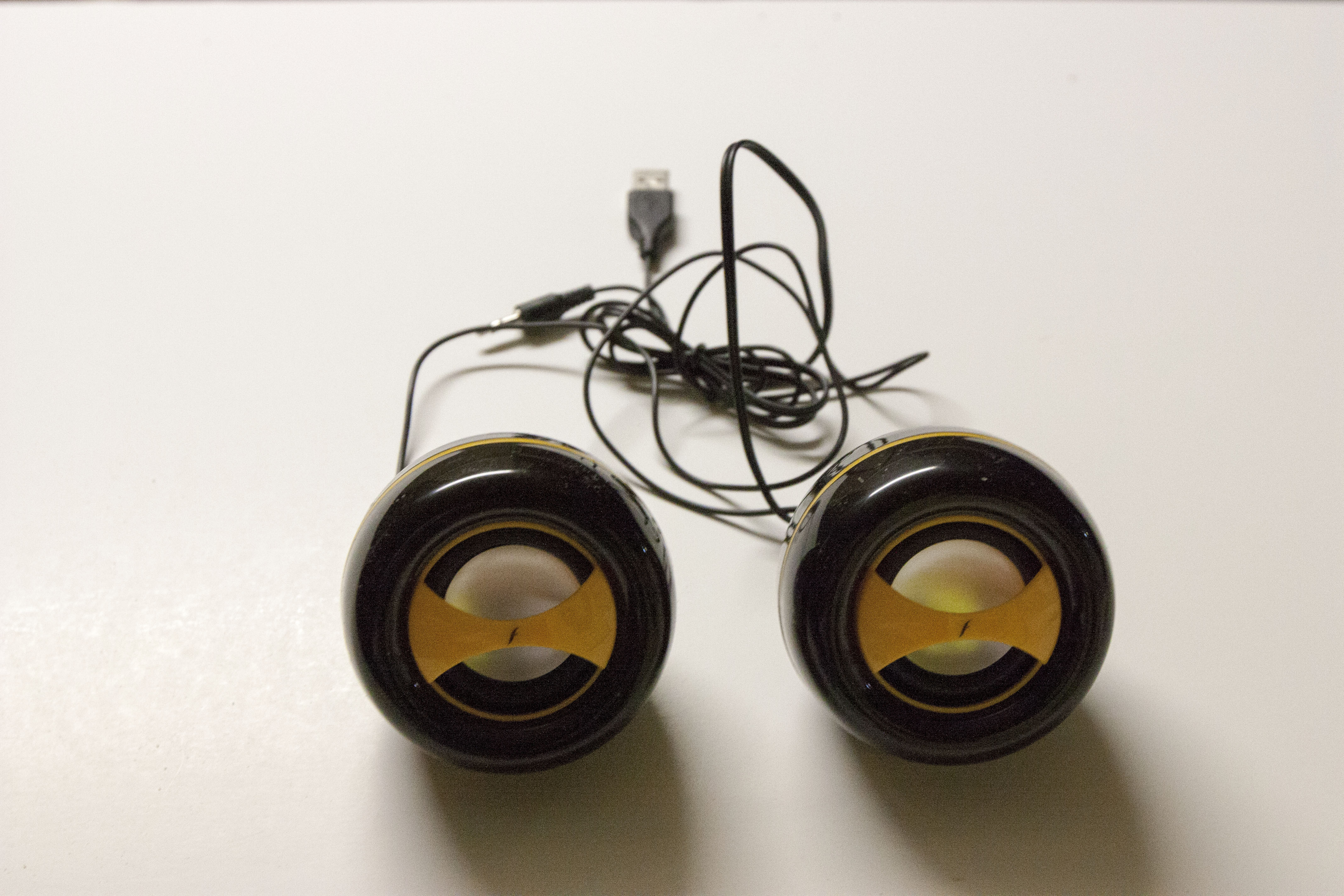
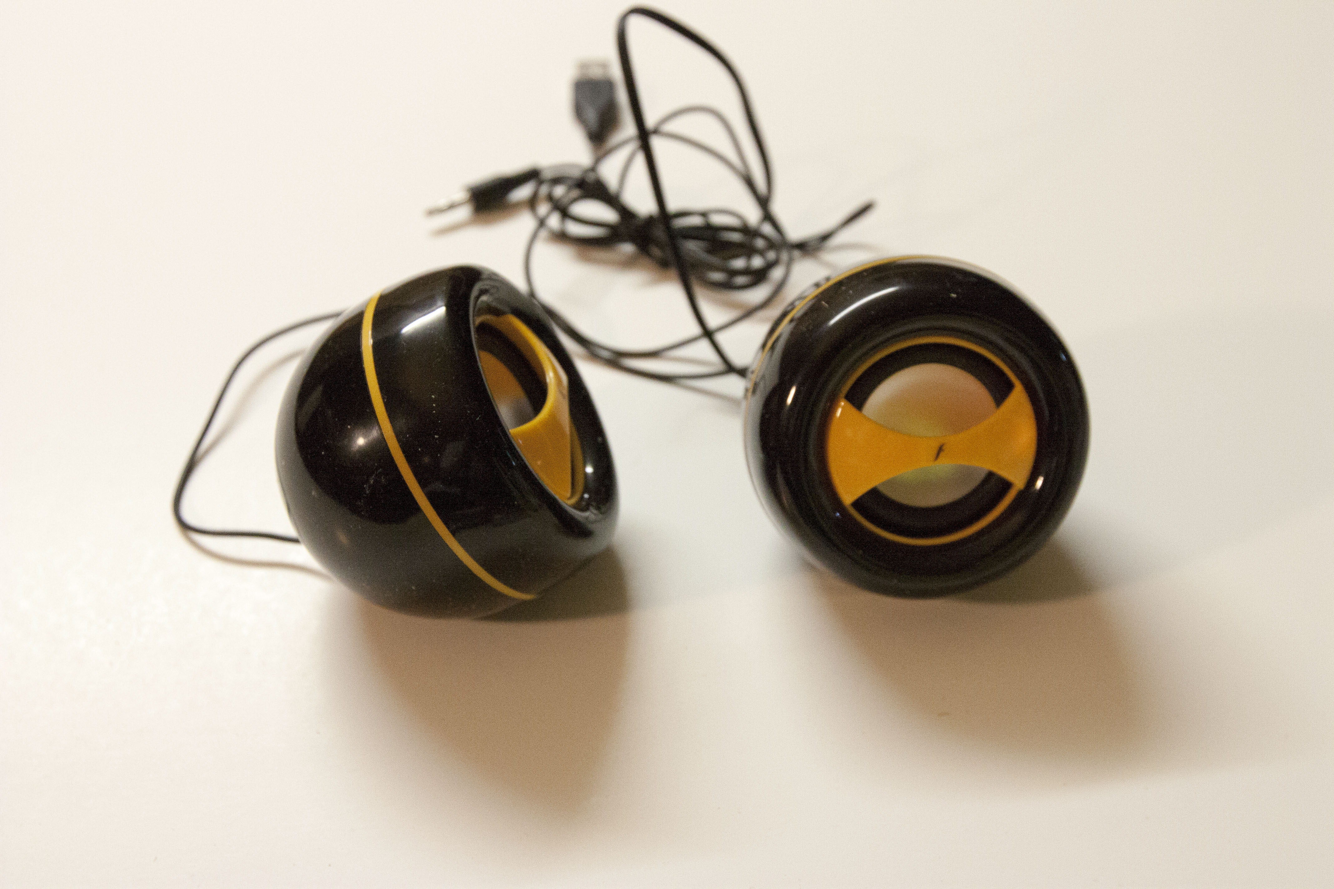
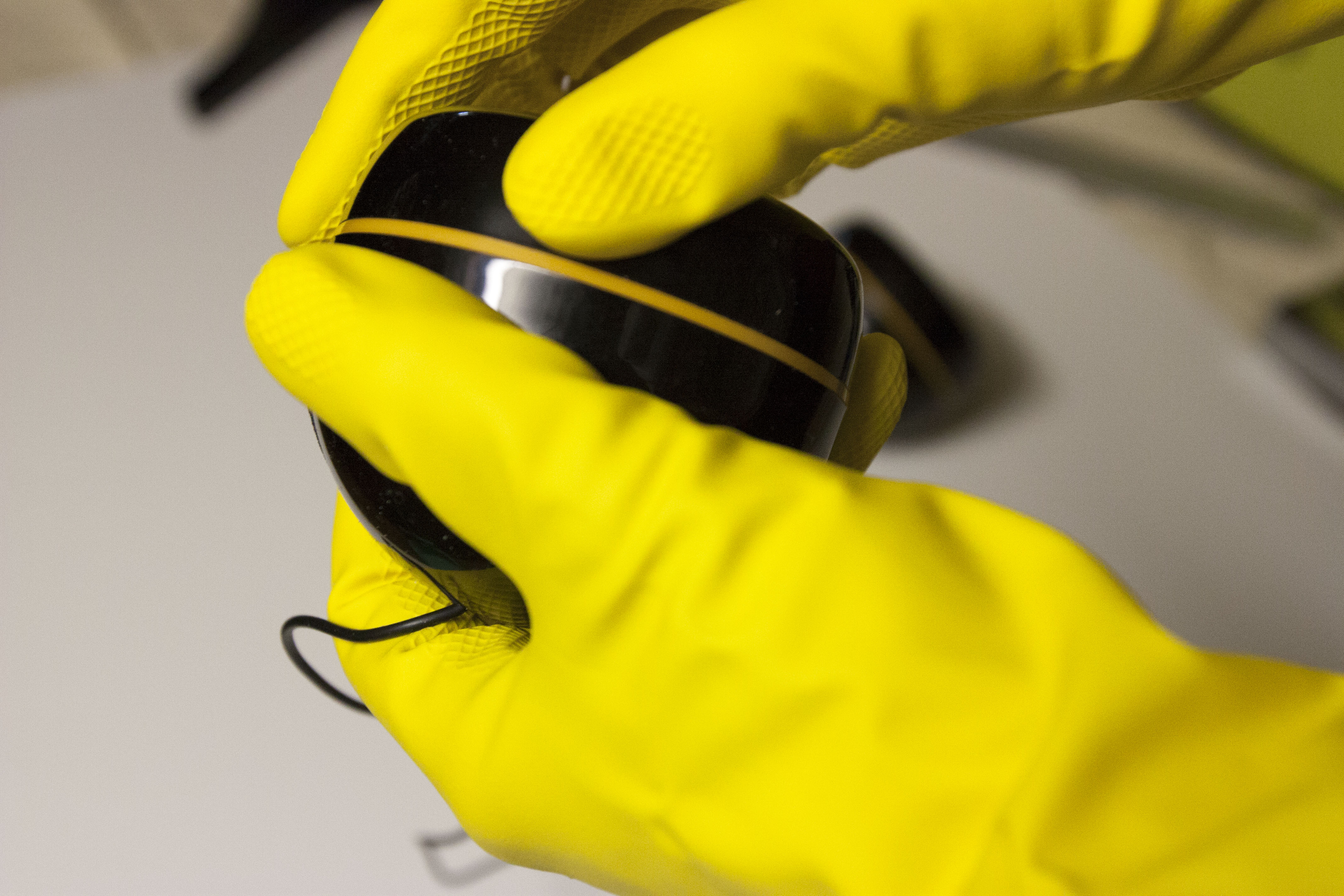
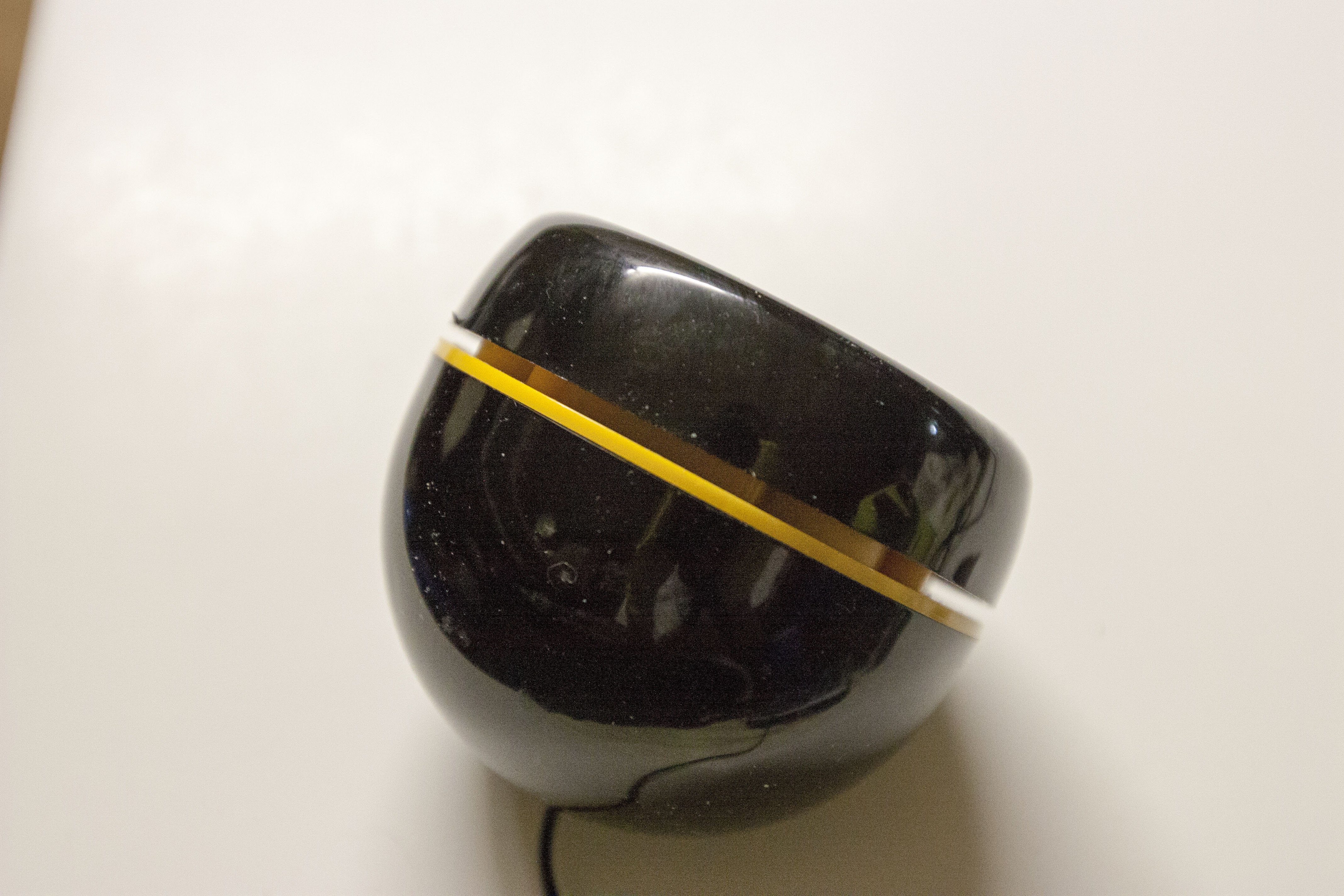
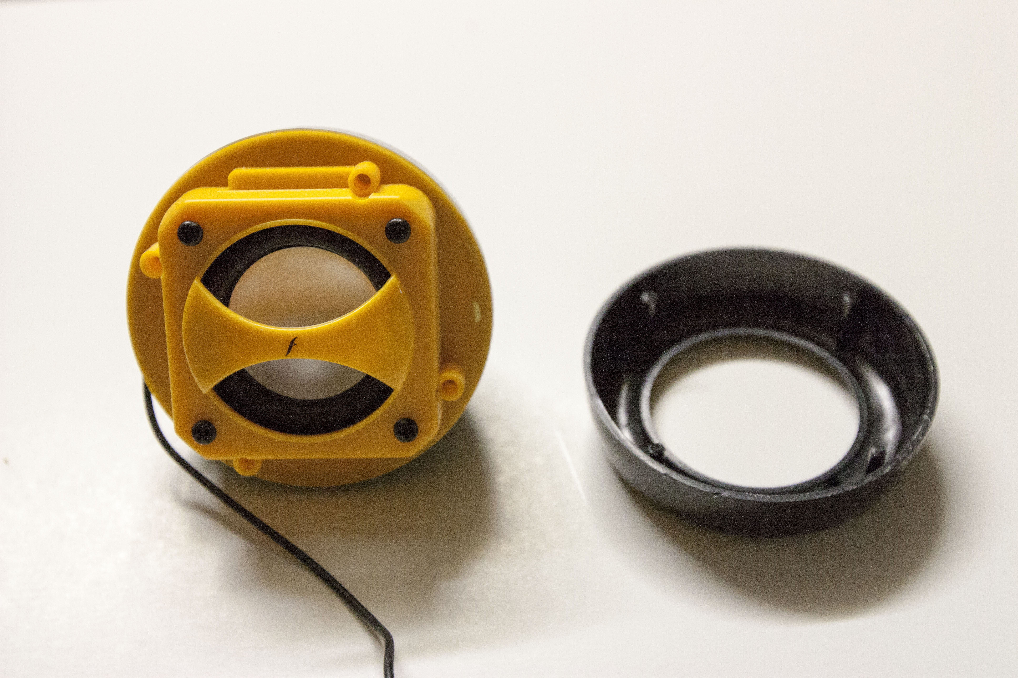
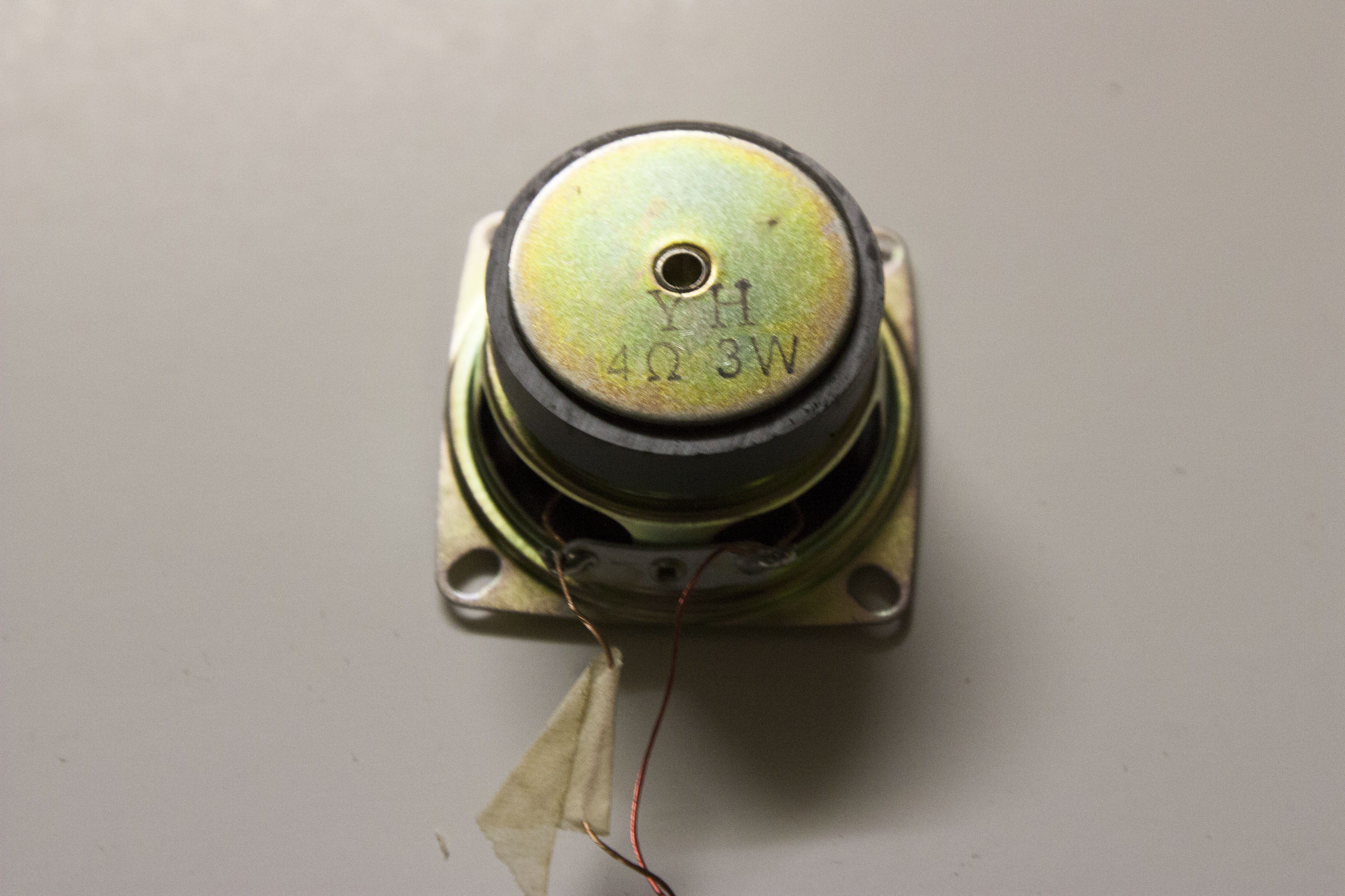
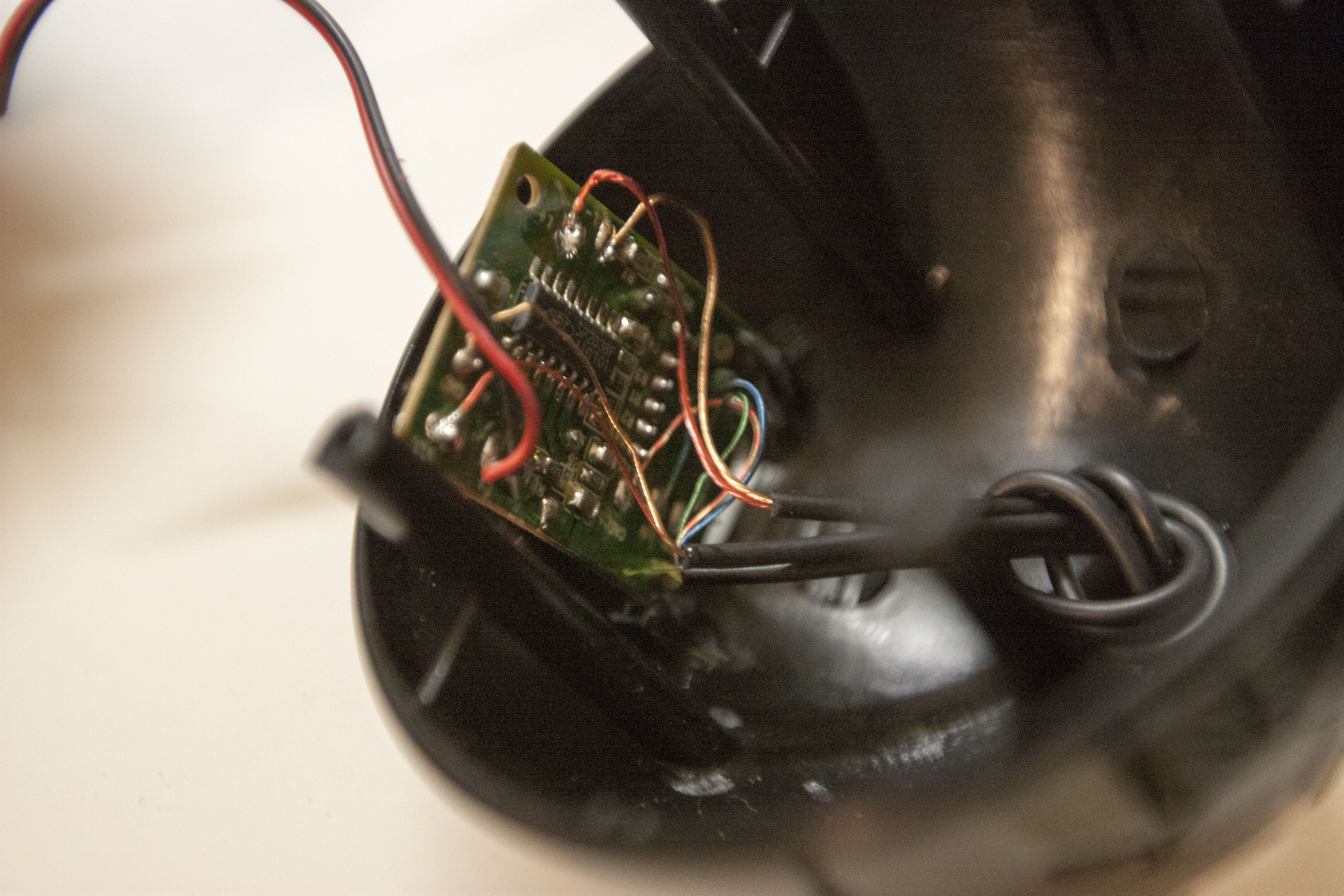
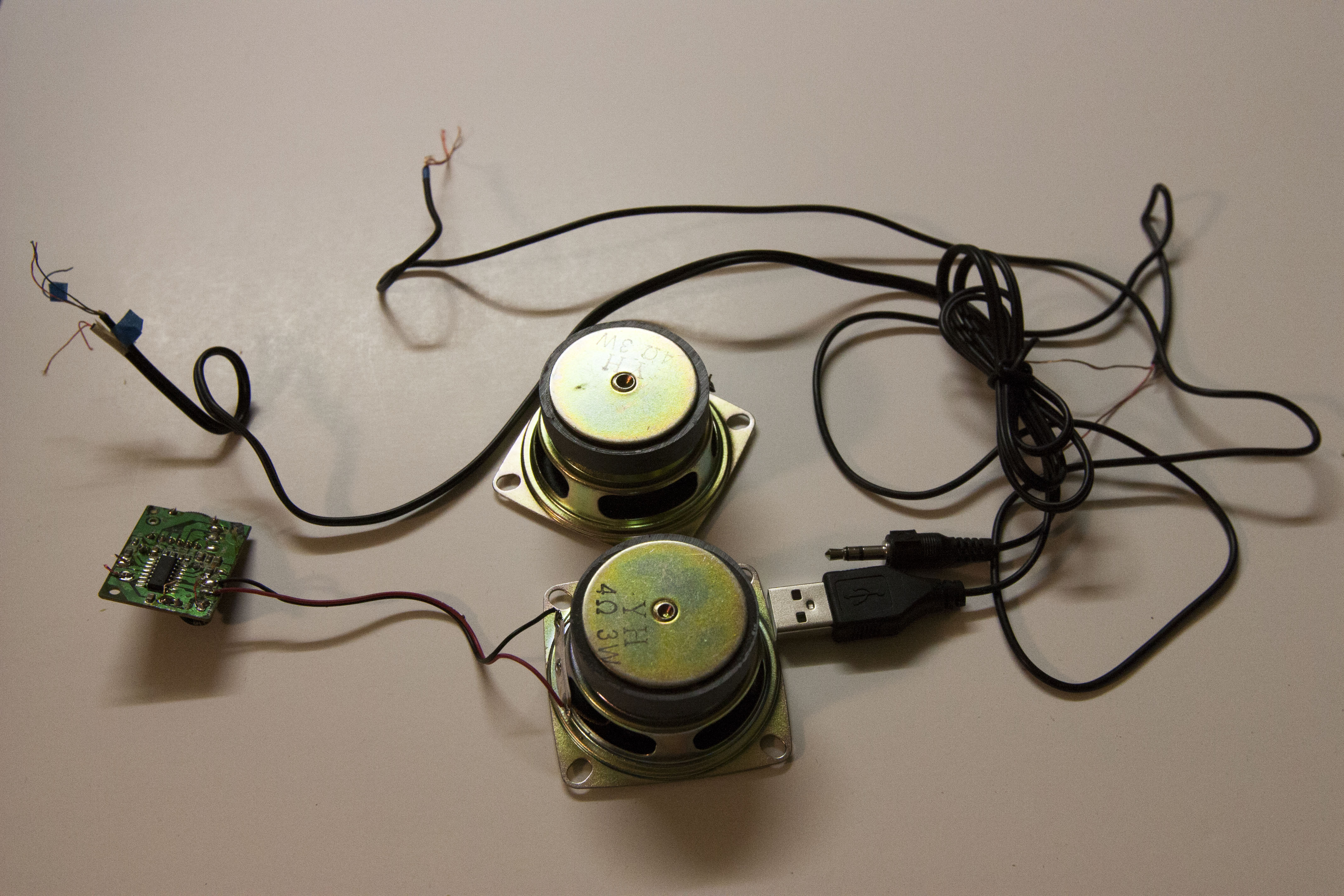
Removing the speakers
- Take the Frisby speakers and use one hand and grab the rear portion and use the other hand to grab the front portion.
- Using a pair of rubber gloves to assist you, Twist and pull the front portion of the speakers until it leaves small gap.
- Insert a coin or ruler and pry open the front portion until the front comes off.
- You will notice 4 screws. Using a Philips #1 screwdriver, remove the 4 screws.
- Take the speaker out and note which wire is which.
- To take the wire completely out of the speaker frame, you either have to cut the wires or desolder the wires on the speaker.
- For the other speaker that has the volume control, make a note of where the wires are located. Desolder or cut the wires from the circuit board EXCEPT the black and red wire for the other speaker.
Painting and Assembly
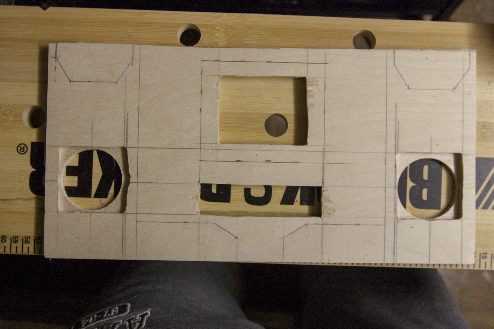
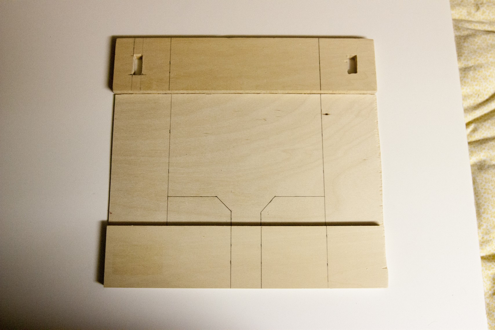
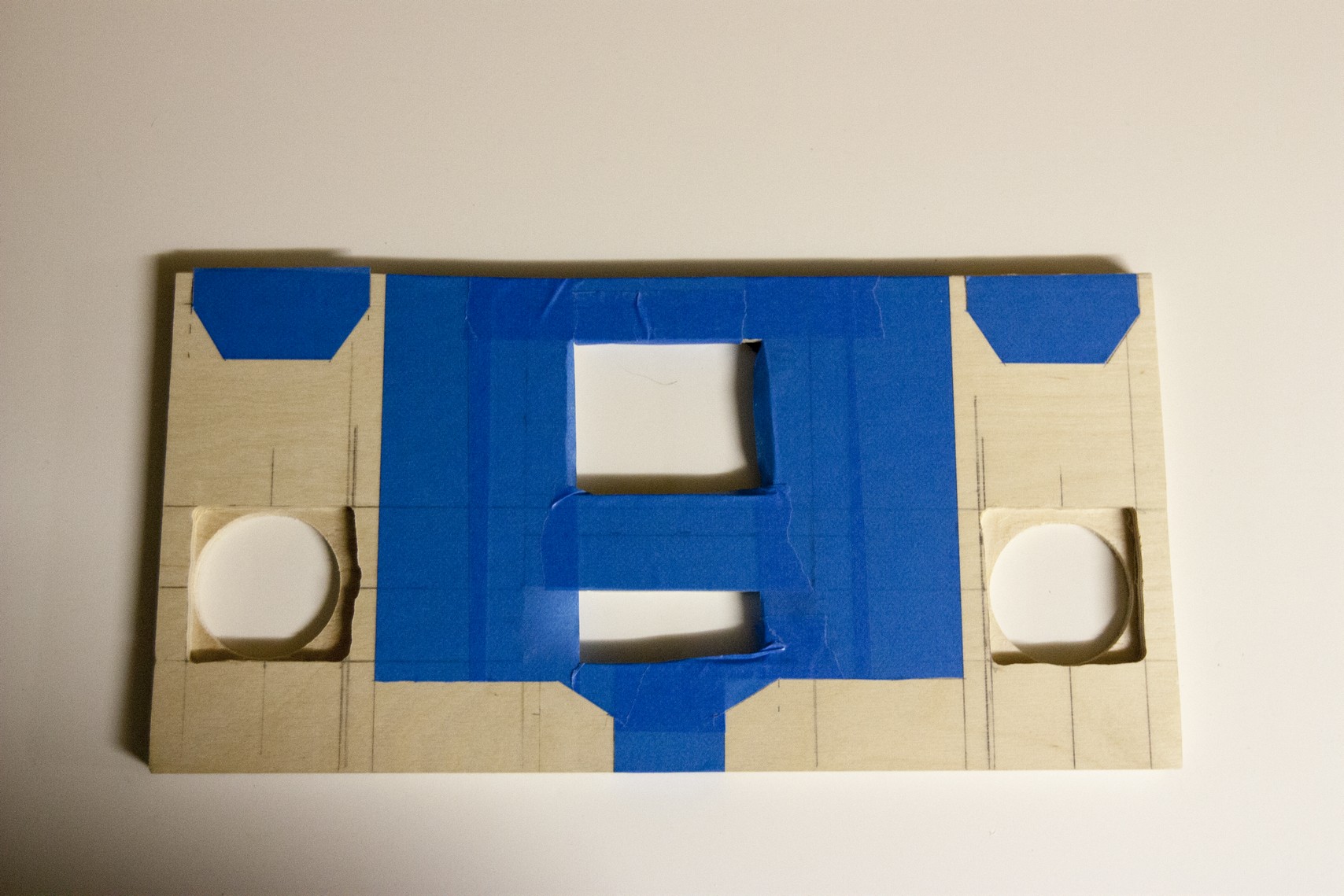
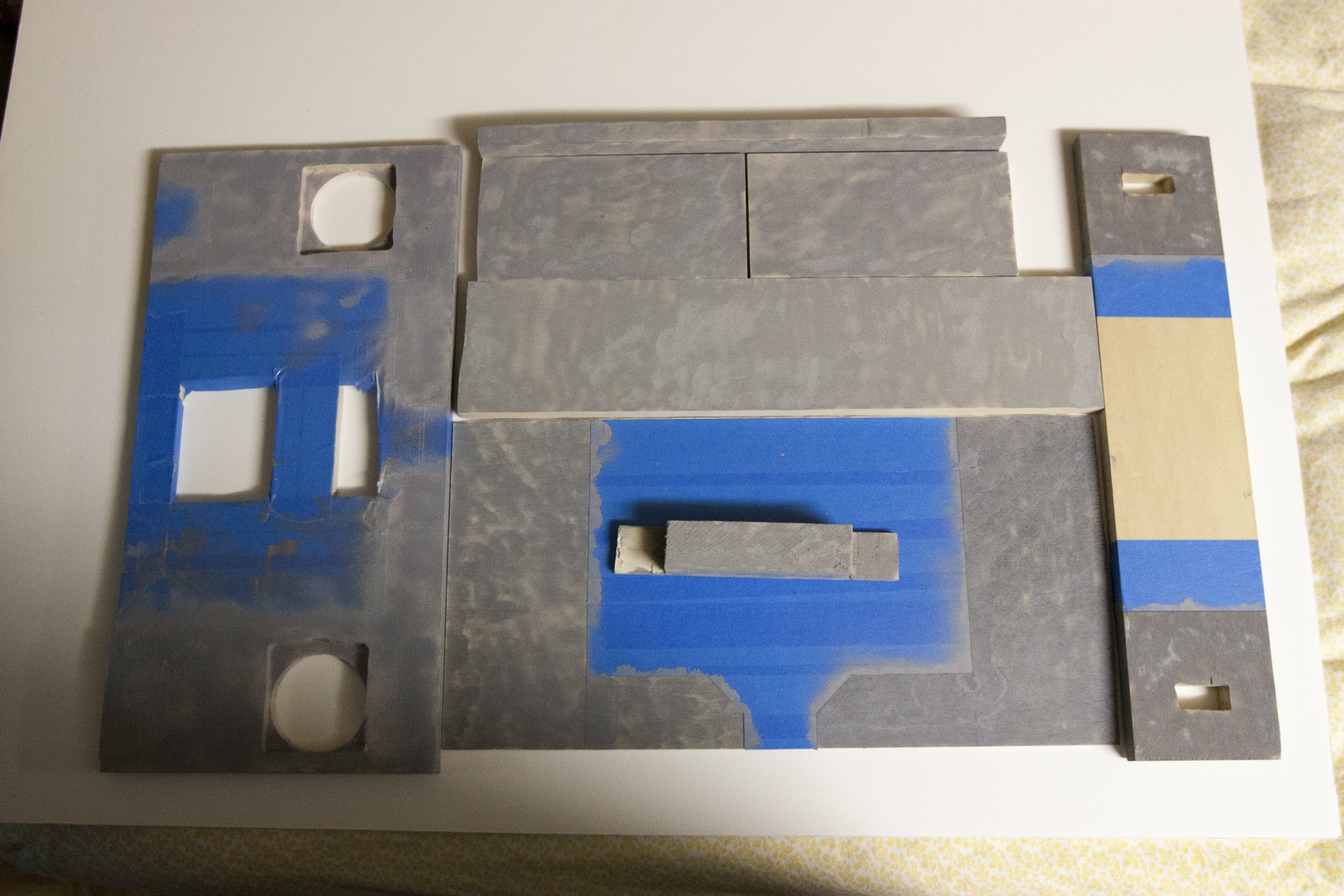
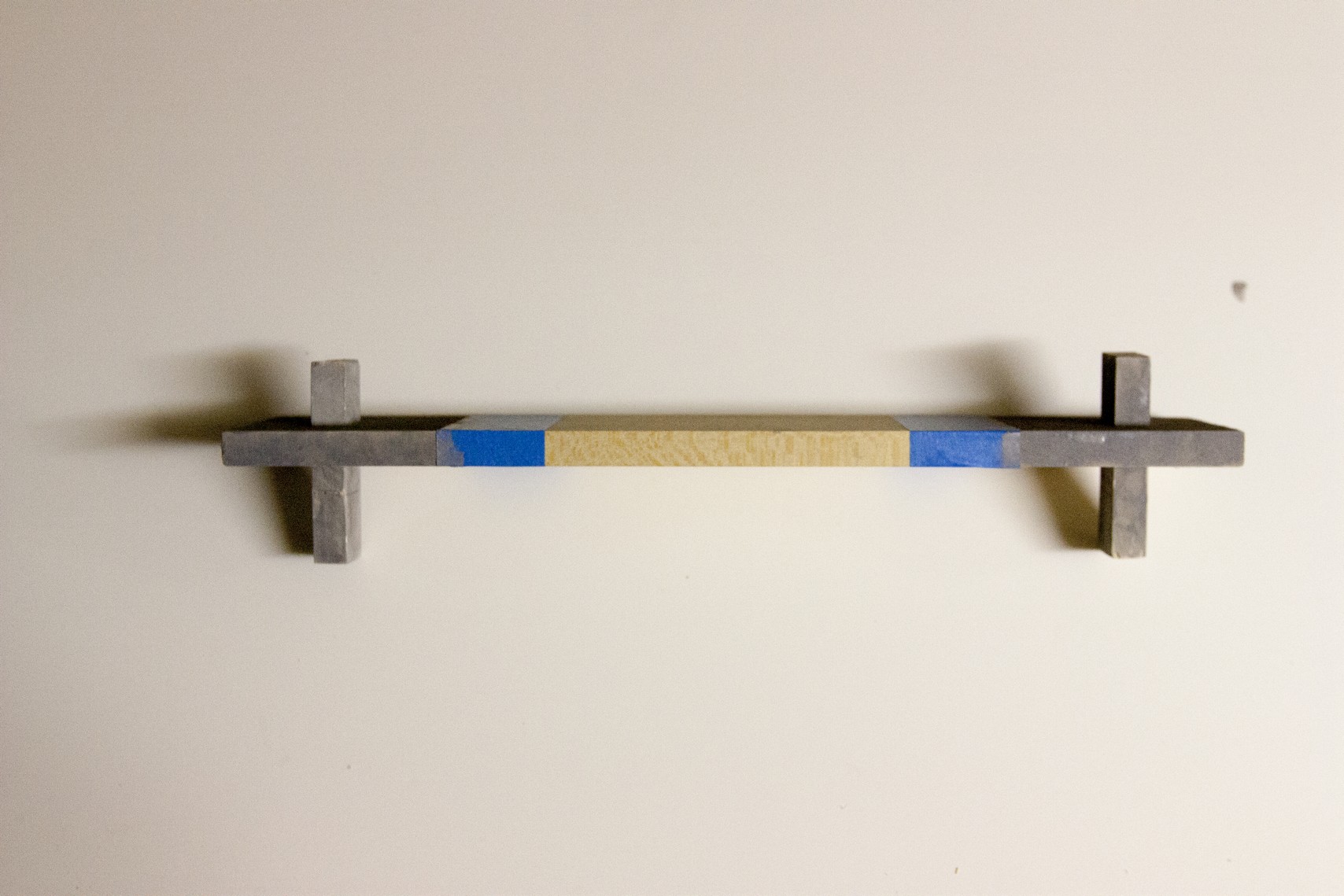
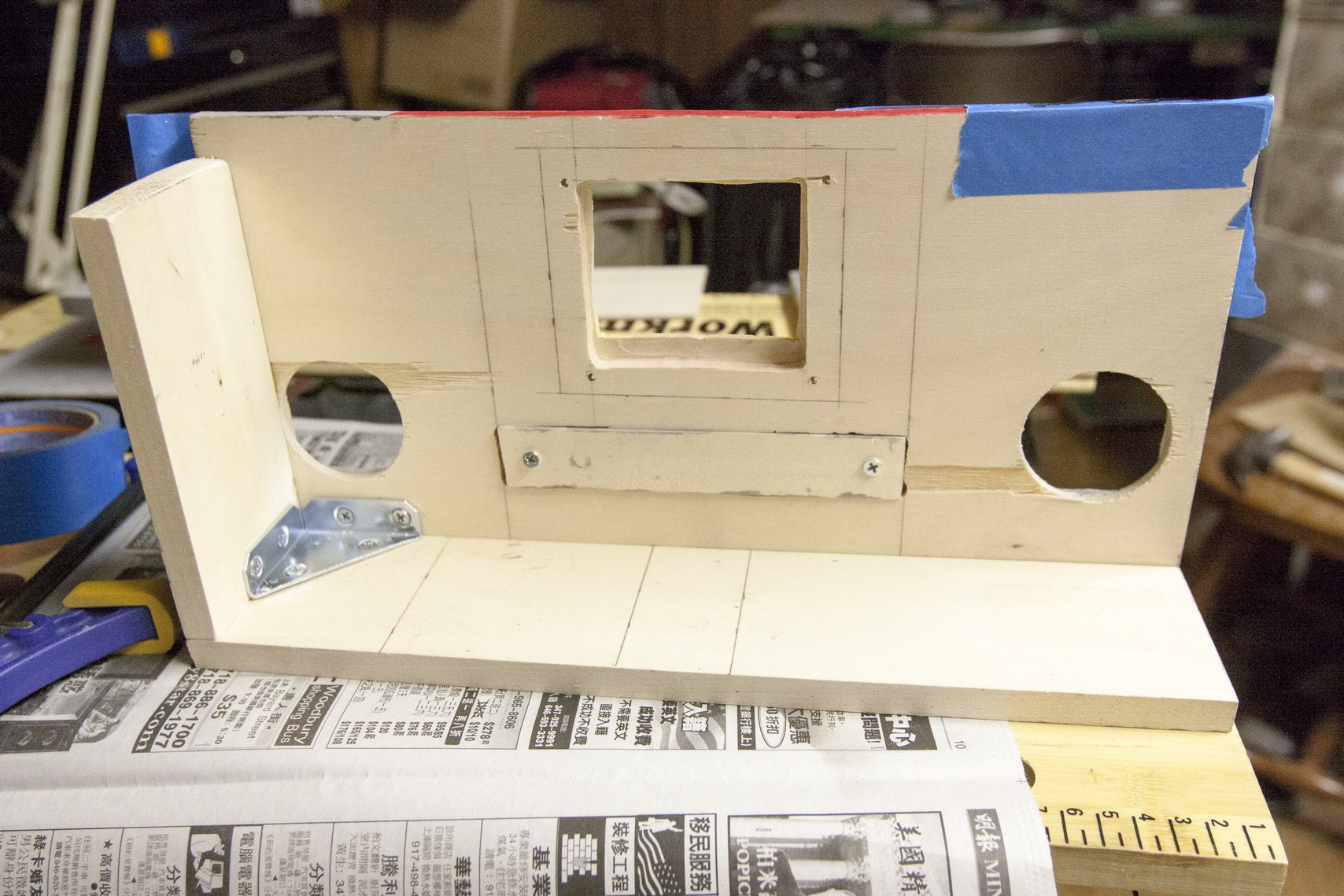
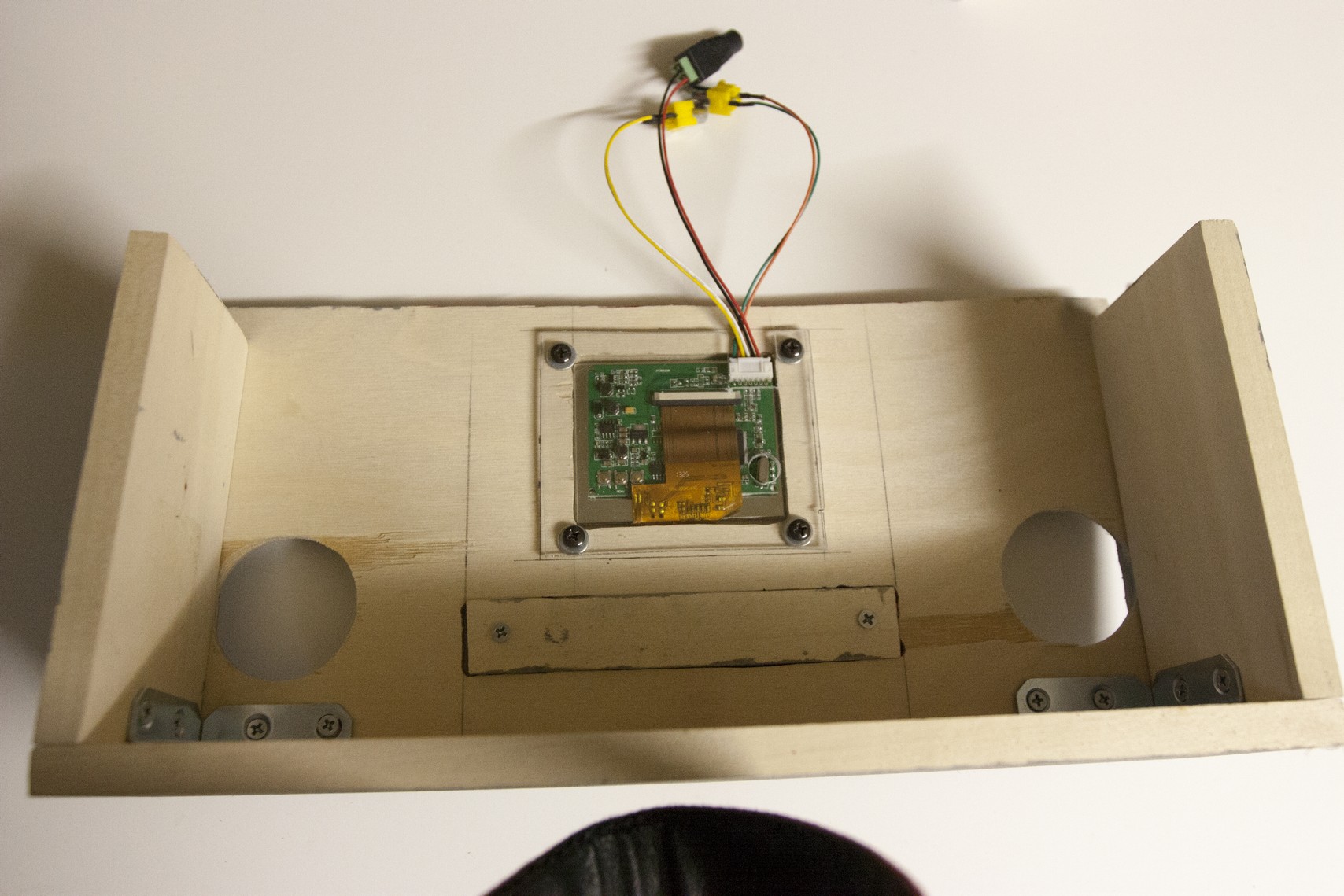
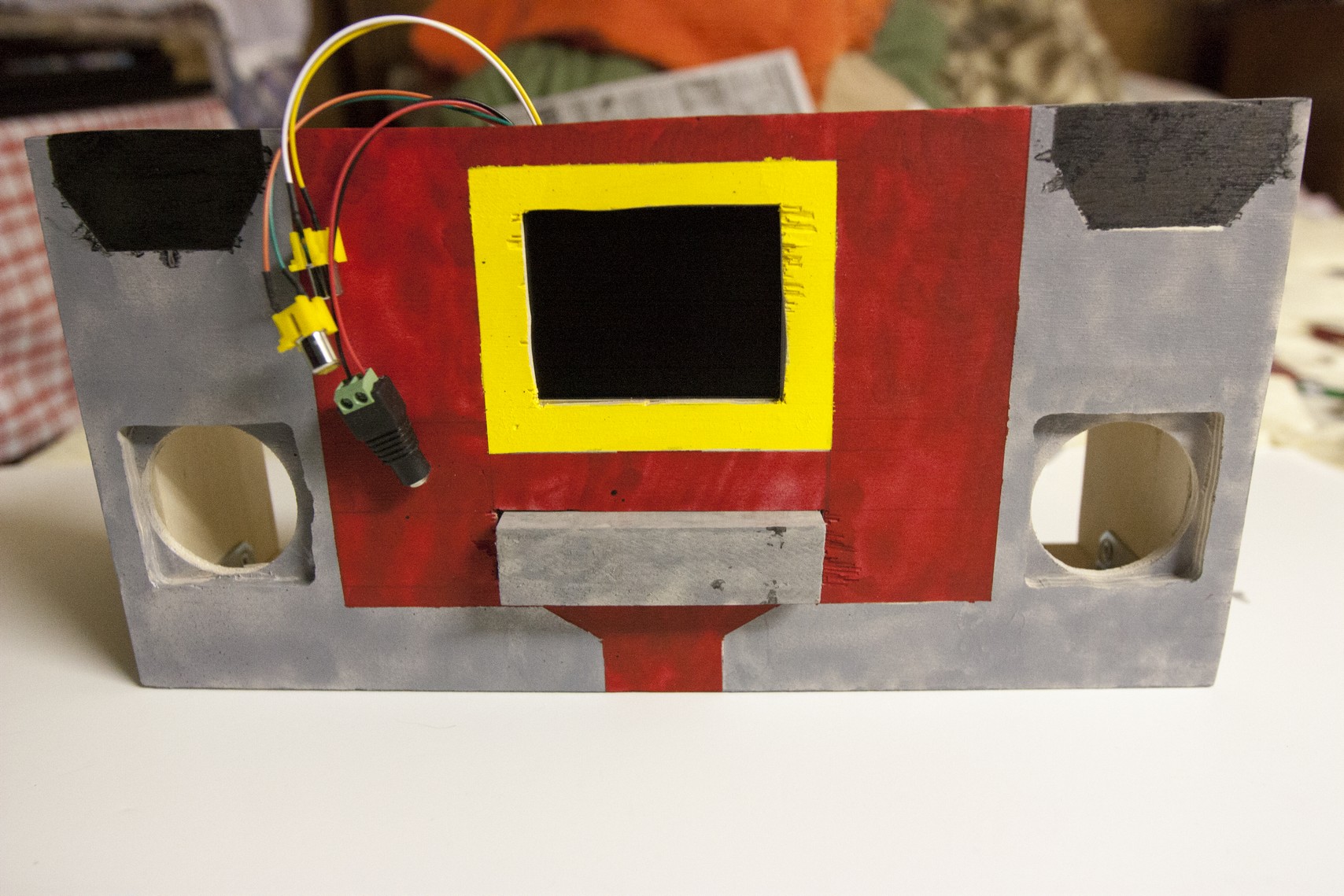
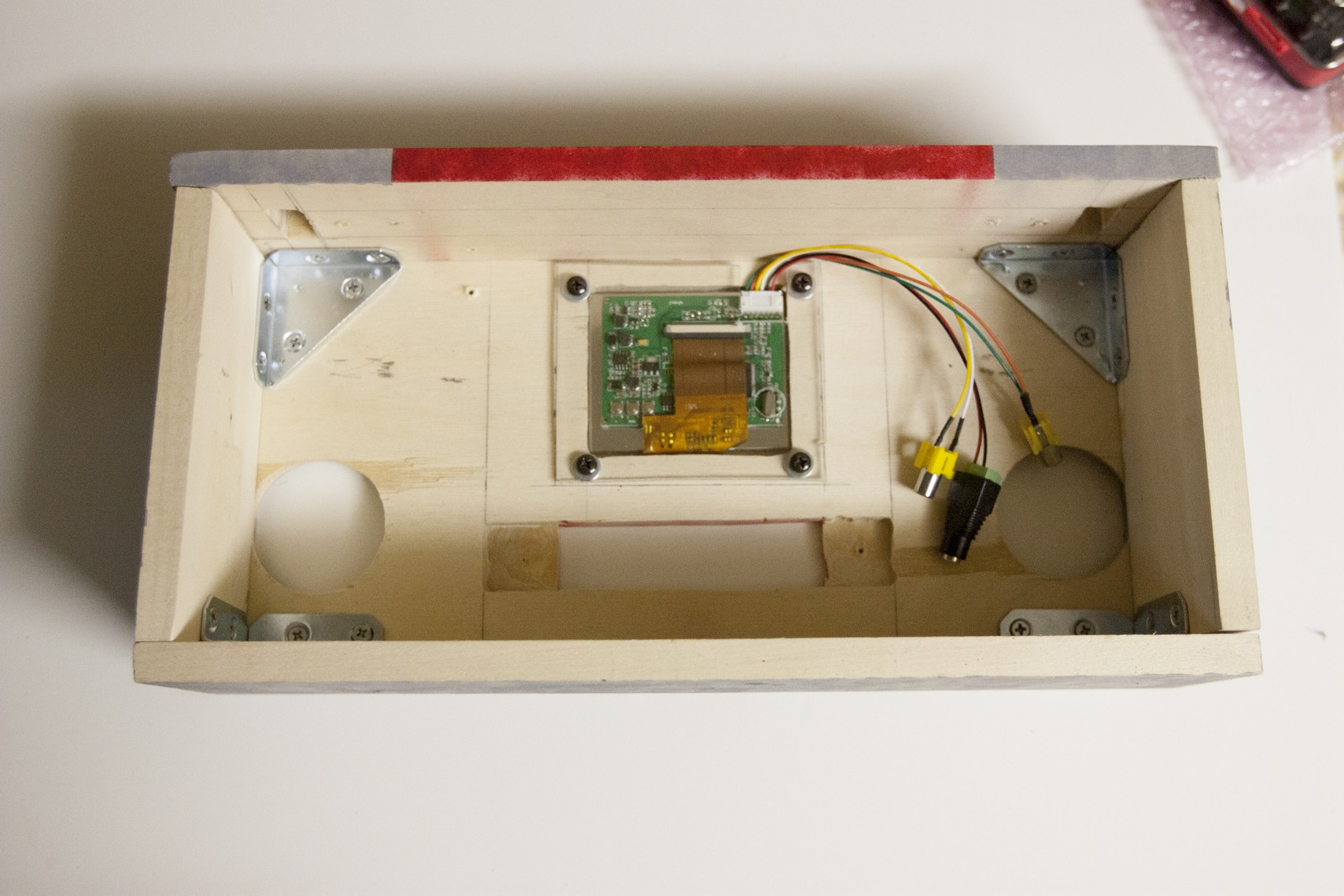
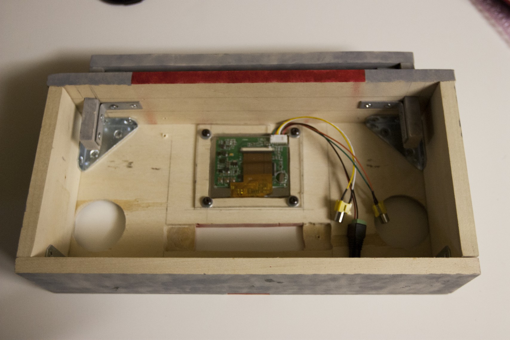
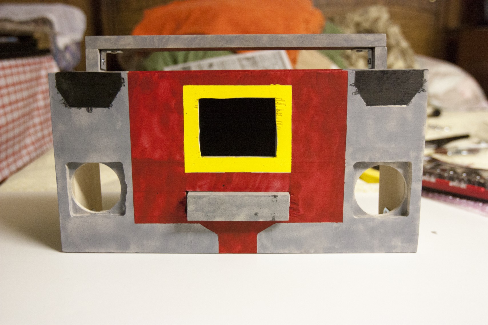
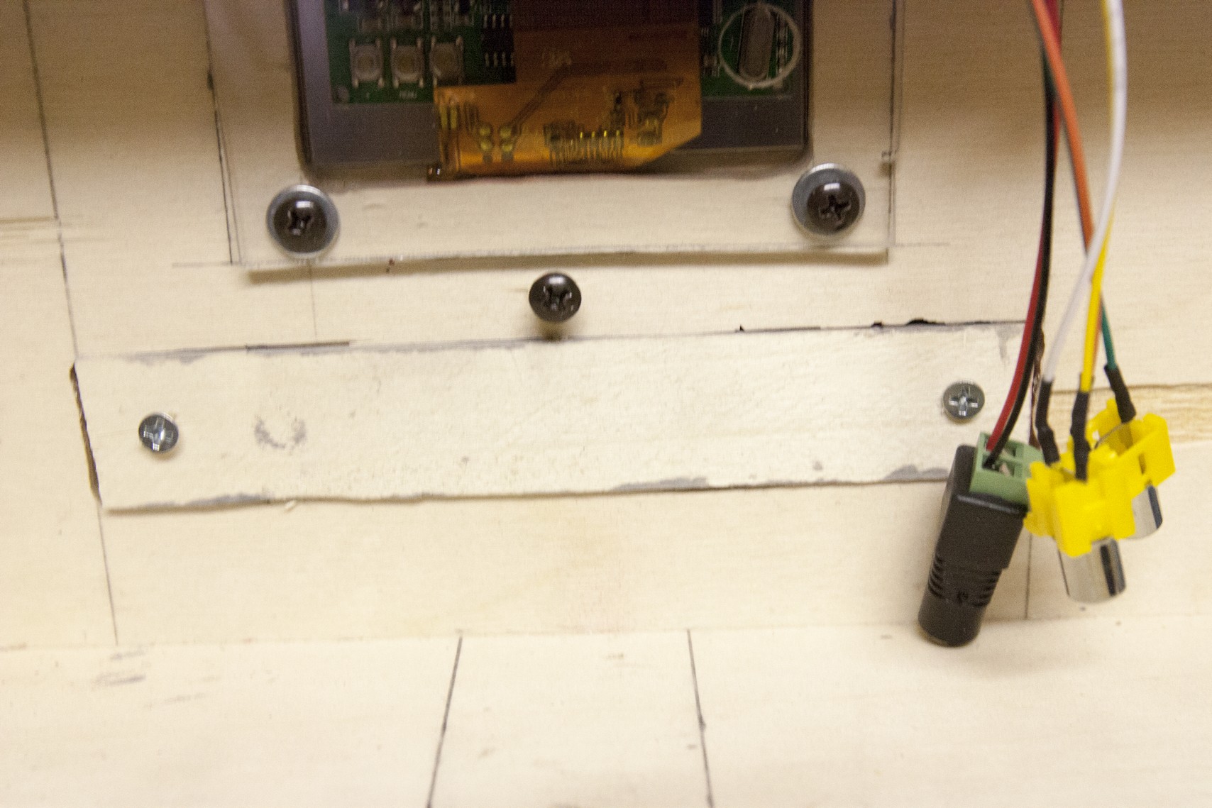
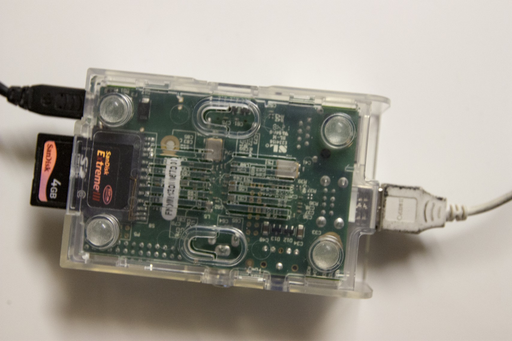
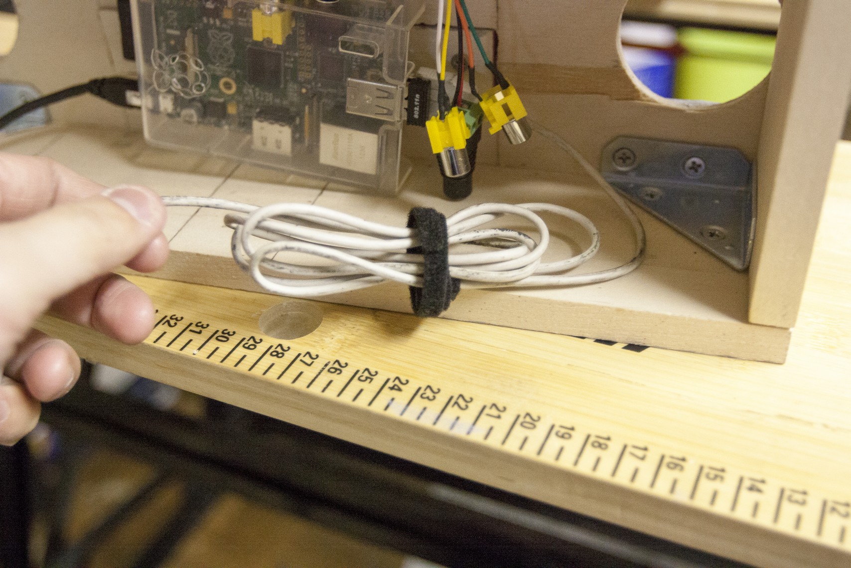
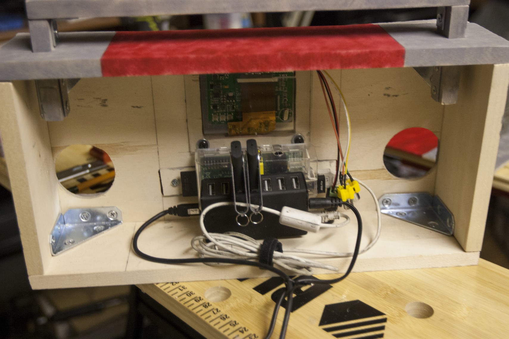
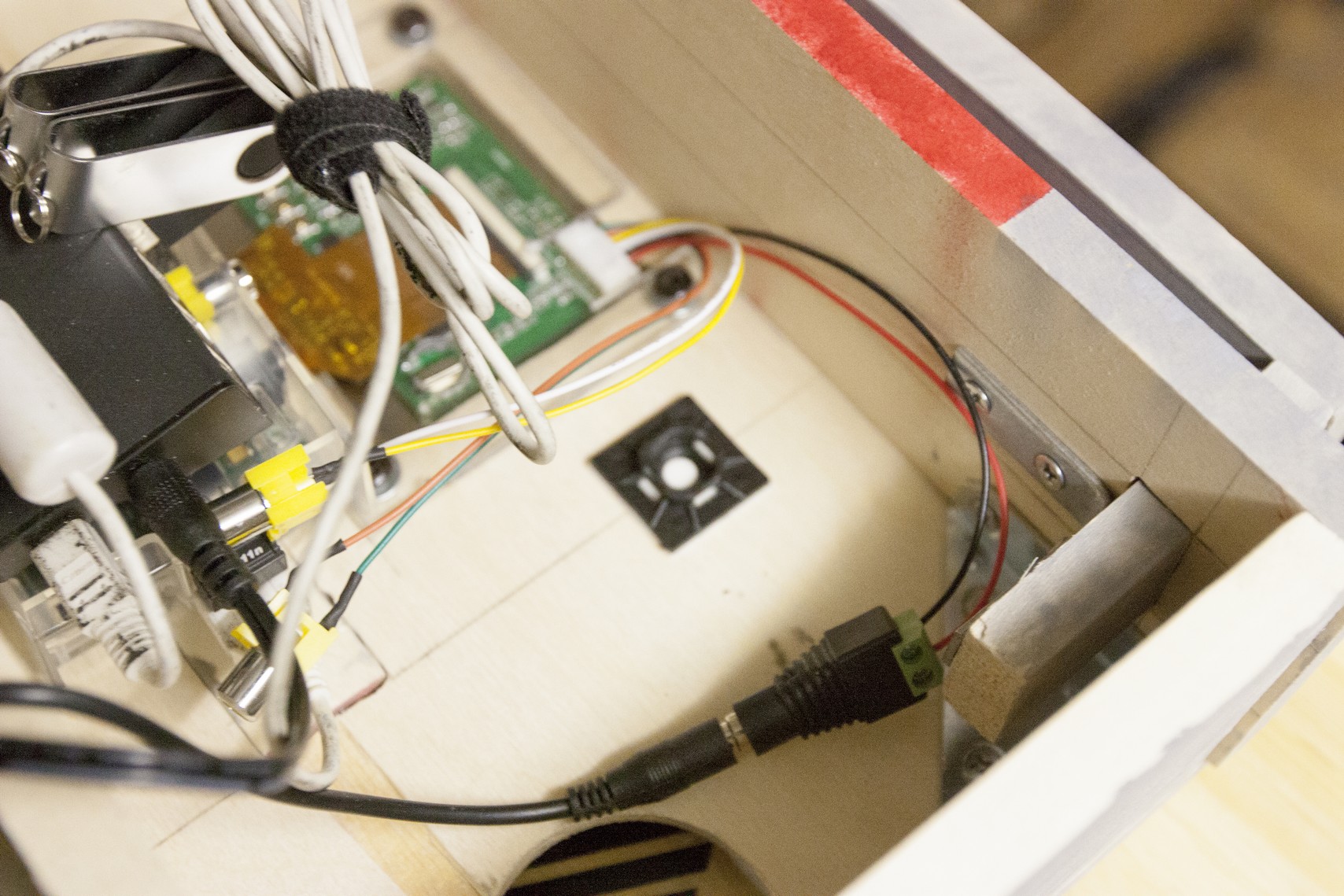
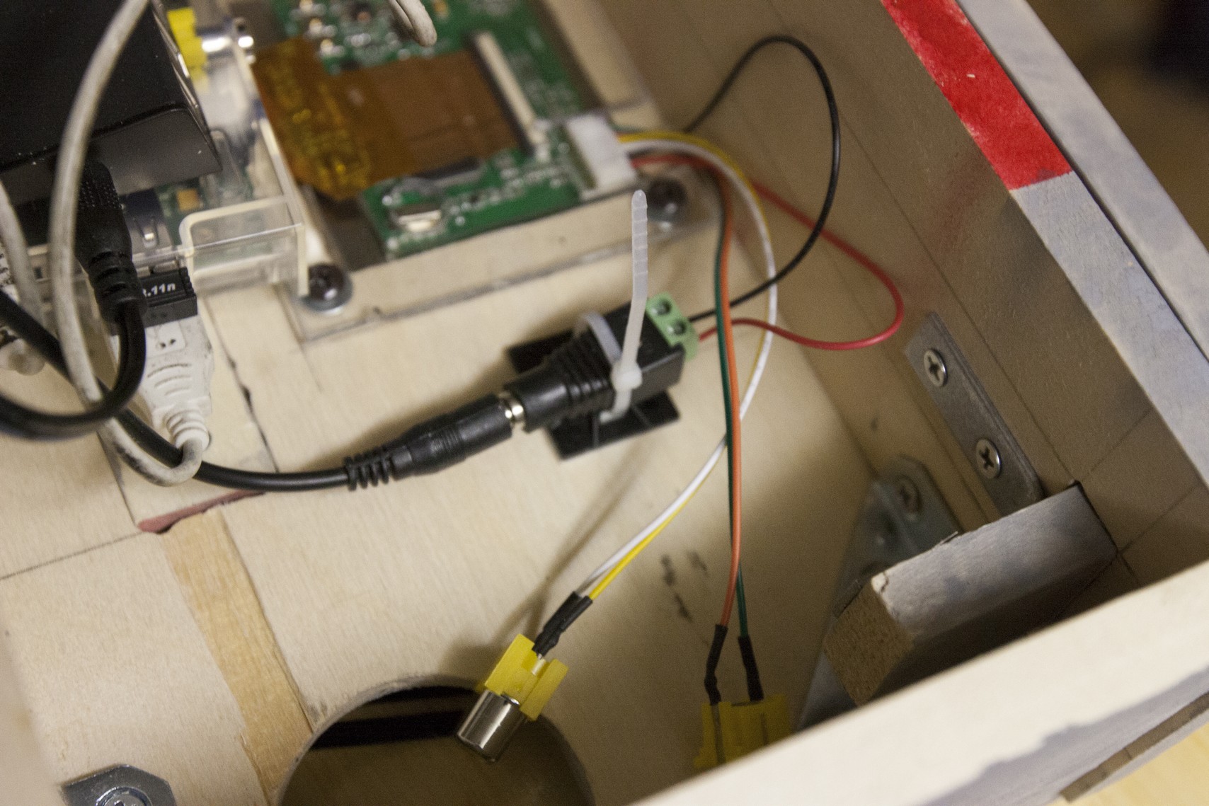
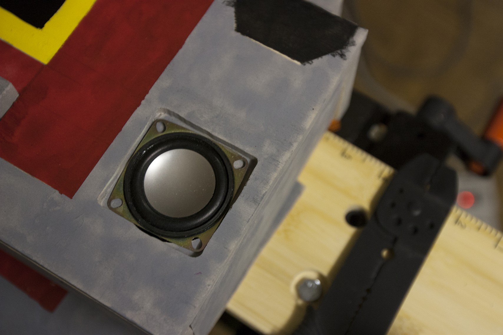
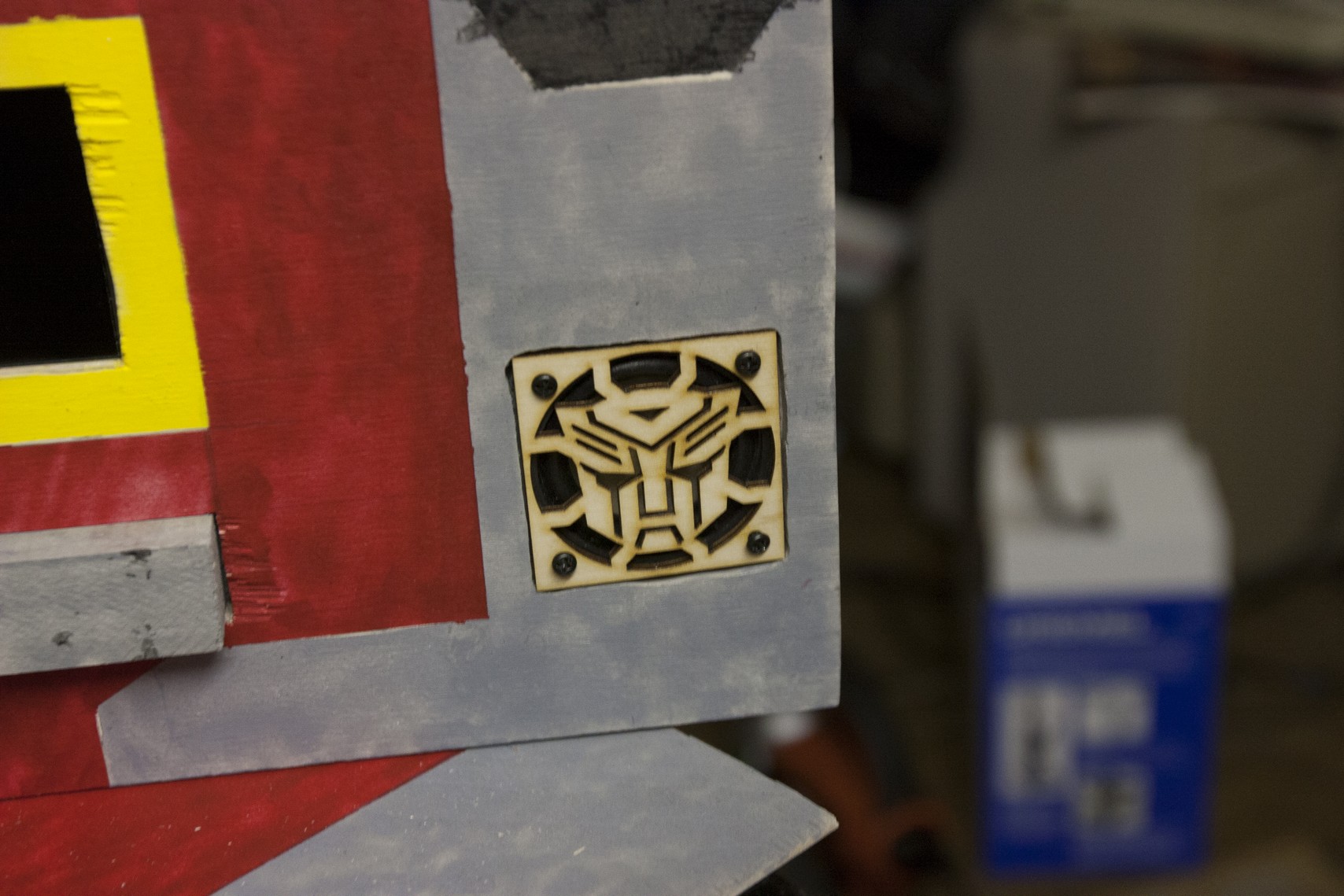
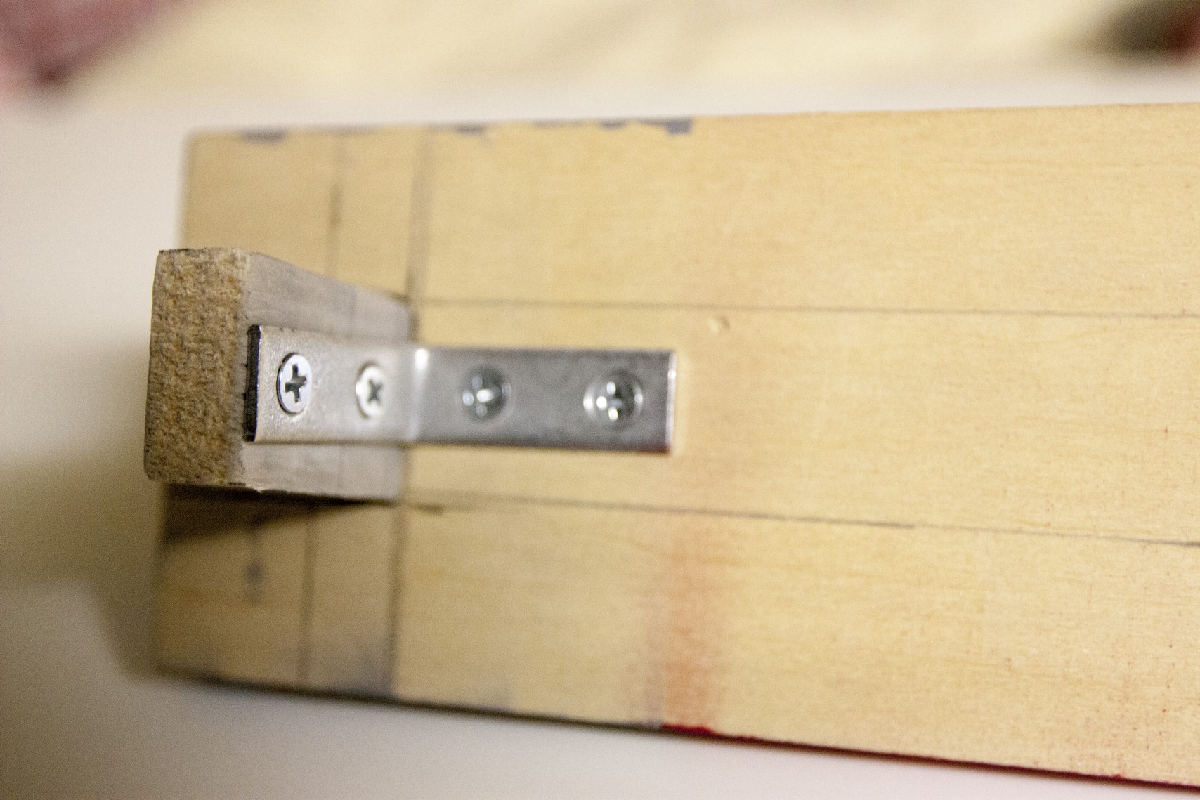
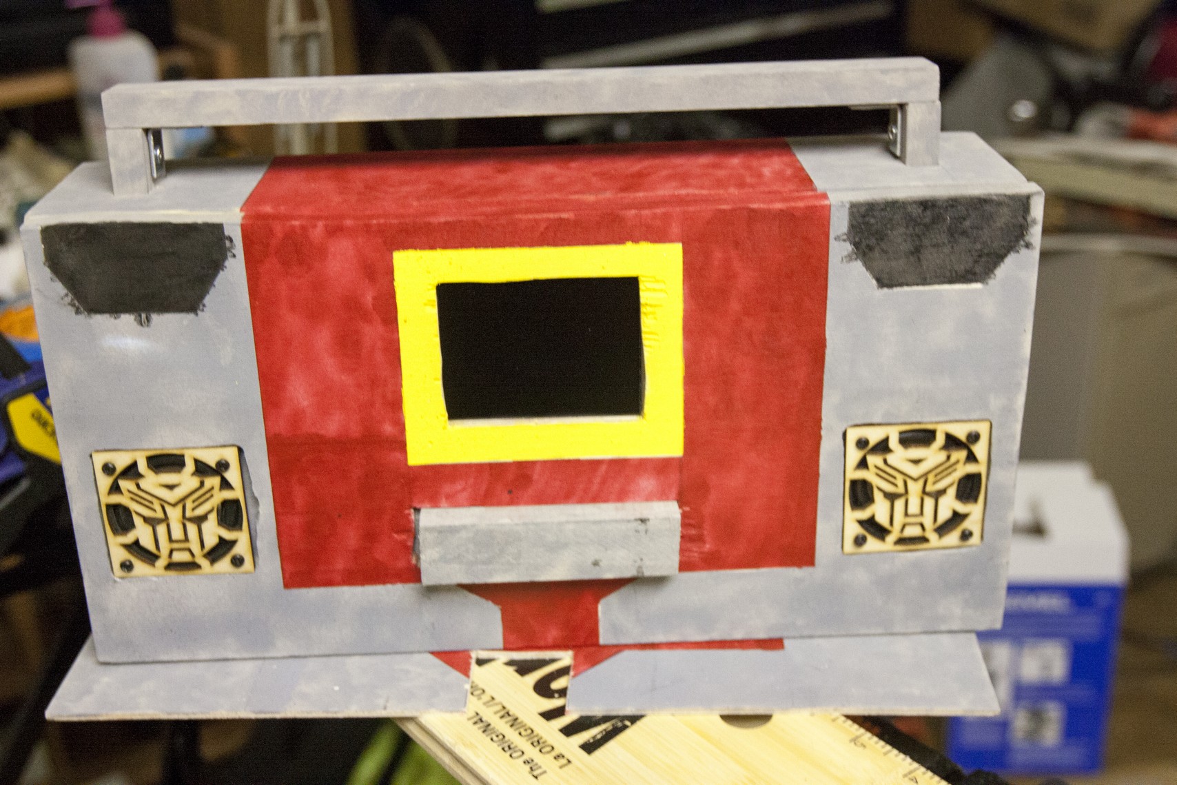
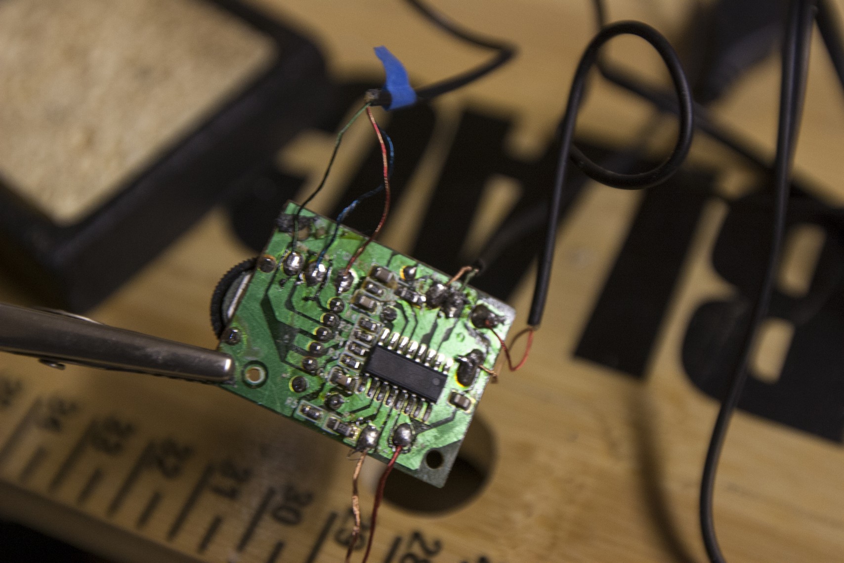
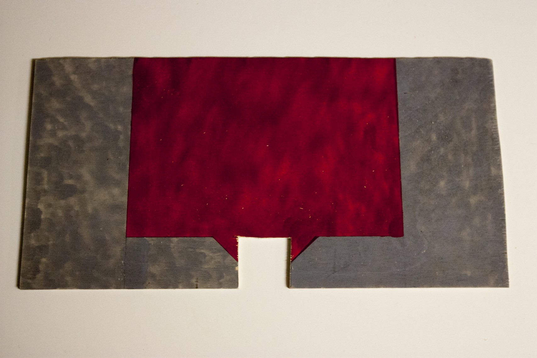
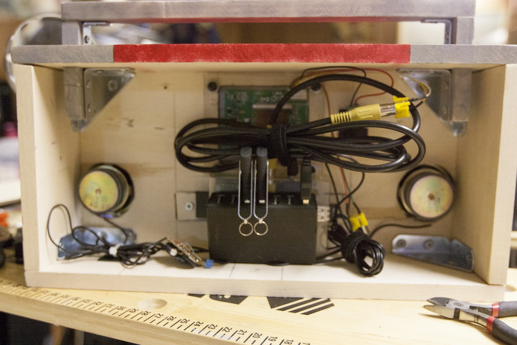
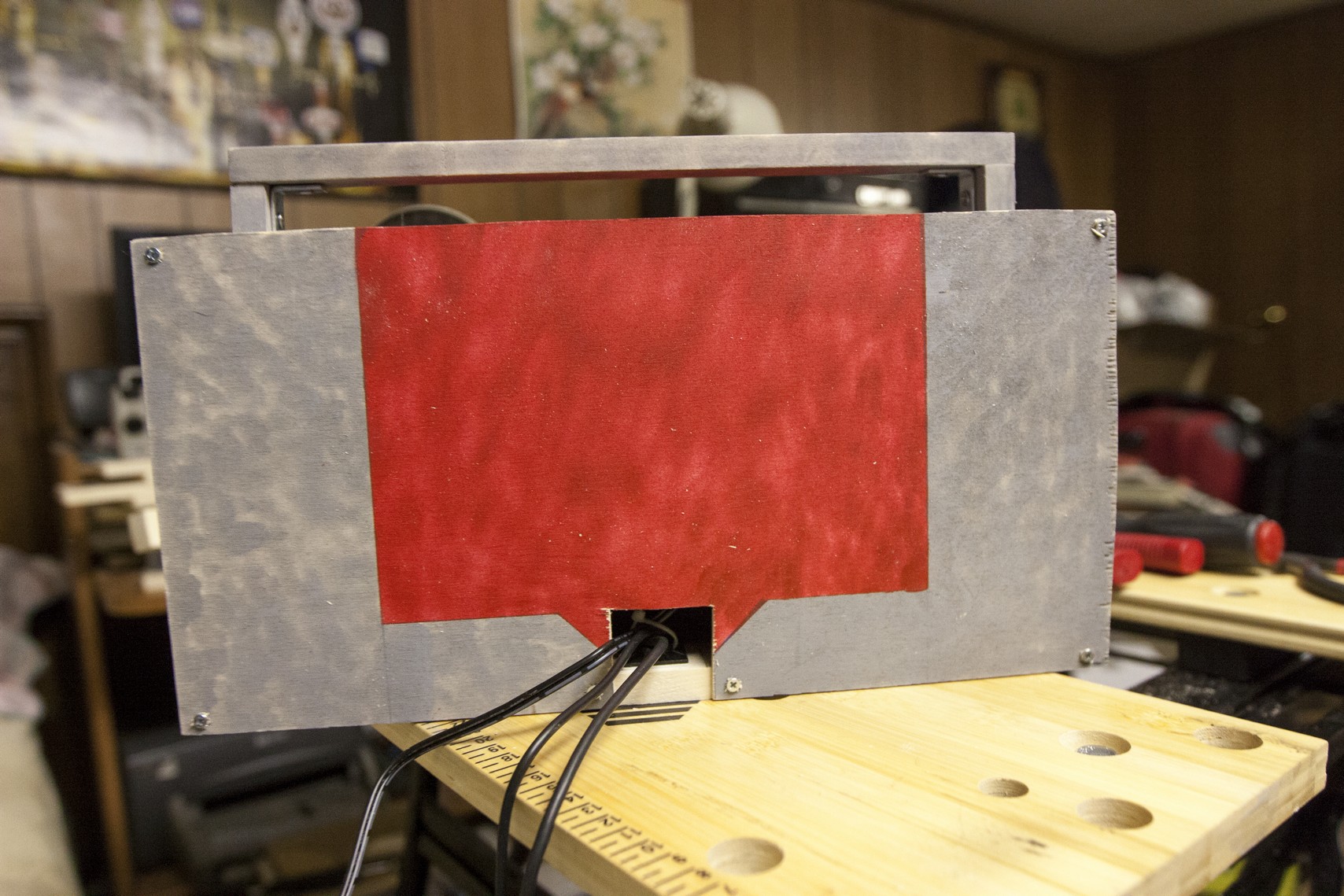
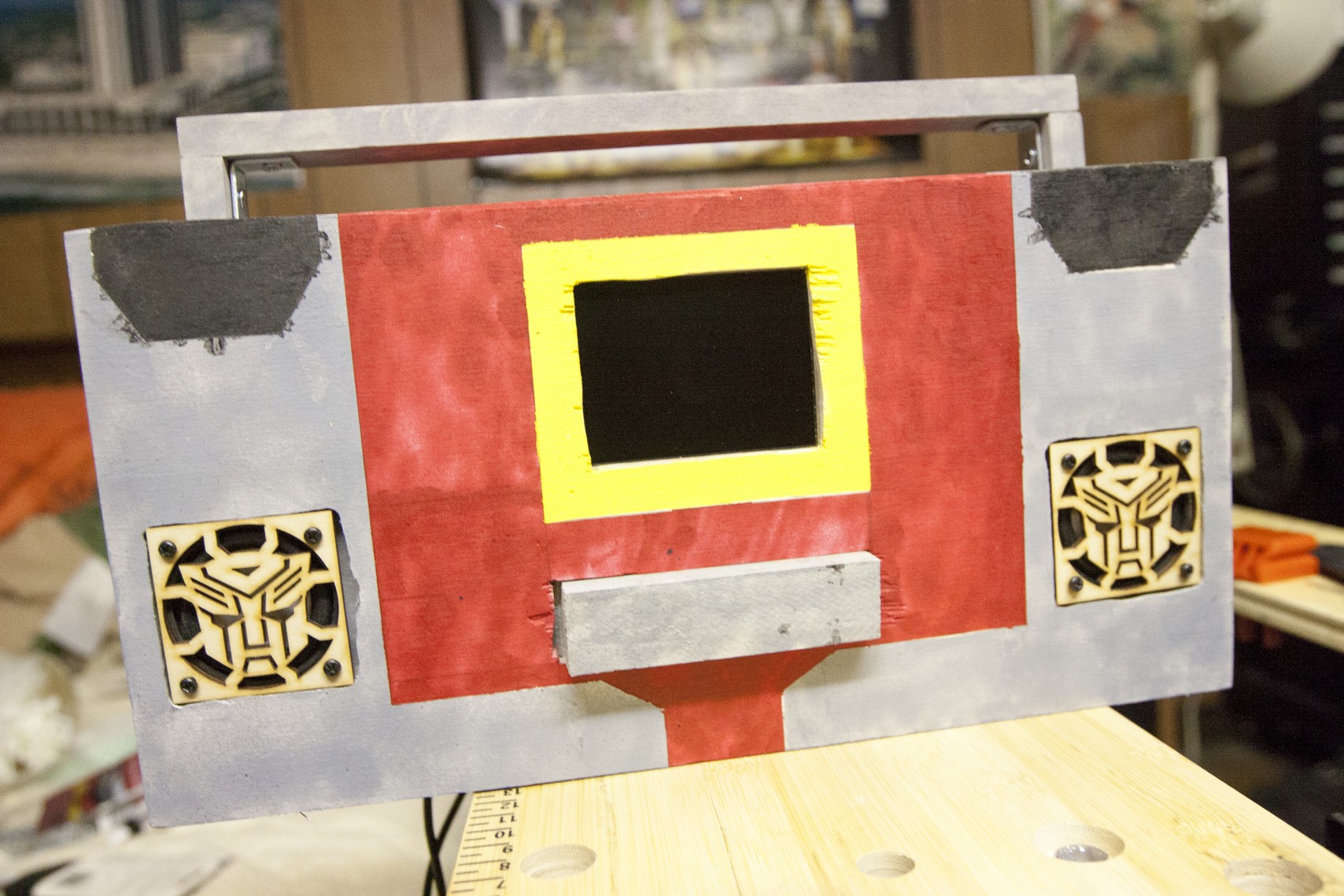
Before painting, use a pencil and mark all the locations so you know what color goes where and then use painter's tape to tape the locations.
Paint gray
Assembly
Paint gray
- sides
- bottom
- top (only 3 inch squares on left and right side)
- from panel everything that is not taped
- back panel, the outer edges
- handle
- front button (1x6)
- *For the front panel, leave a 1/2 inch border around the area of the LCD location and make sure it's taped.
- Paint the middle section red except the 1/2 inch border around the LCD.
- The taped section on the back panel 1/8 inch 7x14
- Inside section of the top board. Should be a 3 inch x 8 inch area.
- 1/2 border around the LCD
- Note: You may have to paint several coats since the yellow is a light color and any type of pencil markings will show up.
- The outer edges where the smallest taped off section is. Refer to the pictures and final product if you are unsure.
Assembly
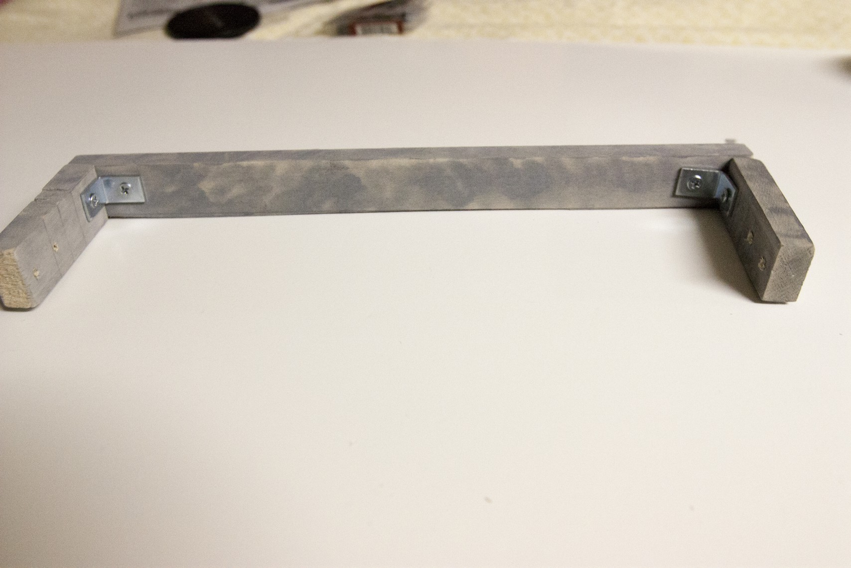
- use a 3/4 inch corner brace and secure both the 1x3 on each end to the 1x12.
- With the 3x14 on the bottom and place the 3x6 with gray facing outwards. Use 2 inch corner braces on each side to to secure the front, bottom and sides. Remove the 1x6 if it interferes but remember to place it back.
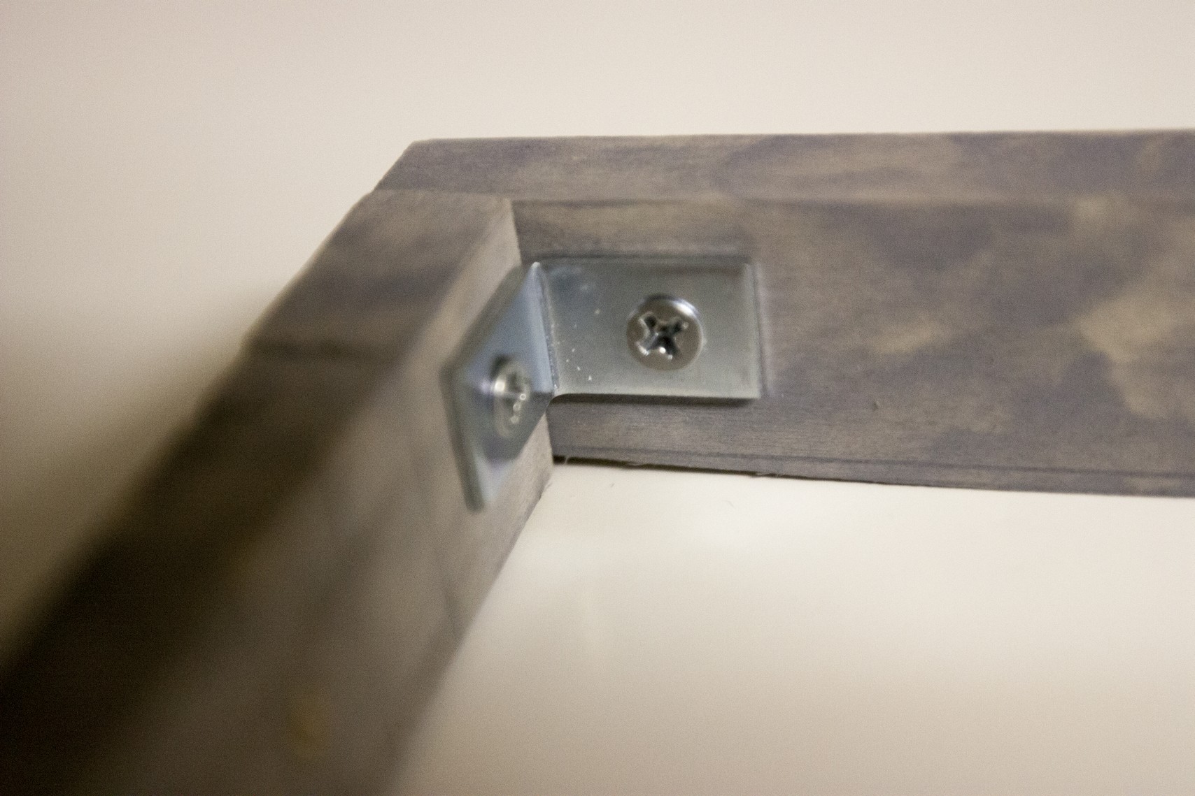
- Take the other 3x14 with the cut holes and use the corner braces and mount that to the top. IF you are using the same corner braces as I am, I recommend you rotate them the same way in the picture.
- Once you've secured the box, it's time to place the handle on.
- When you have secured the handle and all the sides except the back, wire the speakers in.
- Resolder one speaker in and place it in the designated hole. Use the laser cut Autobot logo and align the holes of the speaker.
- Do not tighten it all the way as it could snap the laser cut speaker cover.
- Repeat for the other side.
- Now with all the wires you disconnected earlier, resolder them accordingly.
- Before you put the back piece on, use a computer or laptop and test the speakers to see if it works. Otherwise you have to re check the soldering.
- Organize the wires with velcro and cable management mounts.
- Mount the USB hub to the top of the Raspberry Pi with some double sided mounting tape.
- For the back 7x14 piece, cut a big enough space to allow the power cords to run through.
- To save an extra space on the outlet, use the USB cord for the Raspberry Pi and plug it into the USB hub. Since the USB hub has an external power source, It will provide enough electricity to power on the Raspberry Pi.
- Use #4 screws to mount the 1/8 inch plywood.
- Plug in everything ti see if the screen turns on as well as the Raspberry Pi. As for the sound, use the XBMC controller on the iPad or Android and play a music file.