RaspClaws Robot
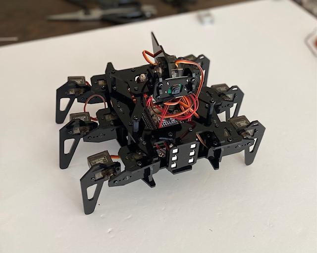
This is my guide on making a RaspClaws Robot.
All my directions are for the Adeept RaspClaws kit, a Raspberry Pi 4, and a computer with MacOS.
Supplies
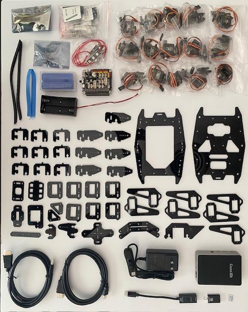
RaspClaws Kit Parts
- Acrylic Body Plates
- 1 x Robot HAT
- 1 x Pi Camera
- 1 x Camera Ribbon
- 1 x mpu-6050
- 4 x Car Lights
- 4 x 3-Pin Wires
- 1 x Battery Holder
- 2 x 18650 Batteries
- 1 x Ribbon
- 15 x Servo Motors
- Included Hardware
Raspberry Pi
- 1 x Raspberry Pi 4 (RPi)
- 1 x MicroSD
- 1 x MicroSD Reader
- 1 x USB-C Power Cable
- 1 x HDMI Cable
Other
- Screw Driver
- Scissors
- Zip Ties
- Keyboard
- Mouse
- Monitor
- Computer
Pi Setup
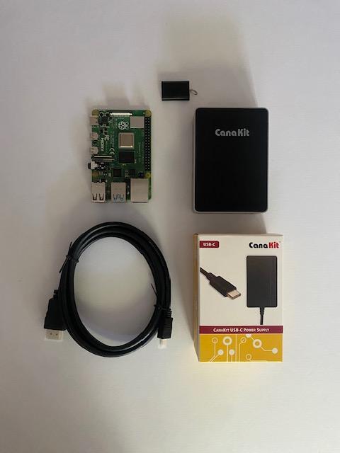
Need:
- 1 x Raspberry Pi 4
- 1 x MicroSD
- 1 x USB-C Power Cable
- 1 x HDMI Cable
- Keyboard
- Mouse
- Monitor
The first step to having your robot is preparing your Pi.
- Insert a microSD card preloaded with your OS into the RPi. The microSD in my kit was already ready, but you can use a microSD reader to write Raspbian to your SD card if needed
- Connect a keyboard and mouse to the RPi and a monitor via HDMI
- Connect the RPi to power and boot up. Install your OS (Raspbian recommended)
- After the RPi restarts, follow the on-screen directions to finish the initial setup
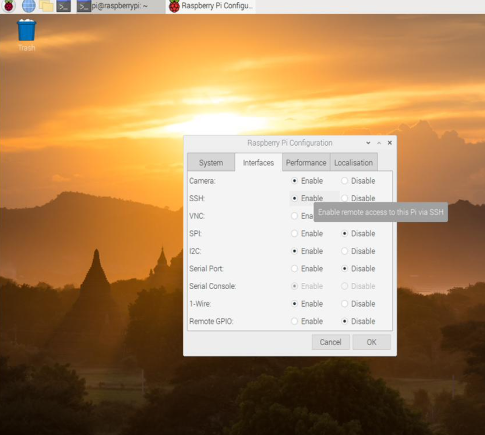
- Click on the raspberry icon in the top left, then Preferences -> Raspberry Pi Configuration
- Enable everything under Interfaces
- Connect your RPi to WiFi
Pi Setup 2 - Robot Ready


Need:
- Configured RPi
- Computer
The next step is preparing your Pi specifically for RaspClaws. After the initial setup, I control my RPi using the terminal on my computer, but you may continue using peripherals if you'd like.
- To access your RPi from your computer using SSH, first locate the RPi's IP address. I checked through my internet service provider
- Open a terminal window and type "ssh pi@[PI_IP_ADRESS]" where [PI_IP_ADDRESS] is the actual IP address
- Press enter, then enter "yes" when prompted if you want to continue
- You will be prompted to input a password. Type in your password (default: "raspberry") even though it appears as if nothing is being entered
- Once logged in, enter "sudo git clone https://github.com/adeept/Adeept_RaspClaws.git" to install the robot program
- Enter "sudo python3 Adeept_RaspClaws/setup.py" to install libraries. The RPi will restart when finished
Camera and HAT
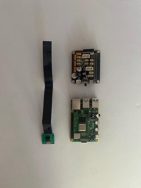
Need:
- 1 x Camera
- 1 x Camera Ribbon
- 1 x RPi
- 1 x Robot HAT
- 4 x M2.5*4 Screws
- 4 x M2.5*14 Copper Standoffs
- 4 x M2.5*10+6 Copper Standoffs
This is the first step in actual robot assembly.
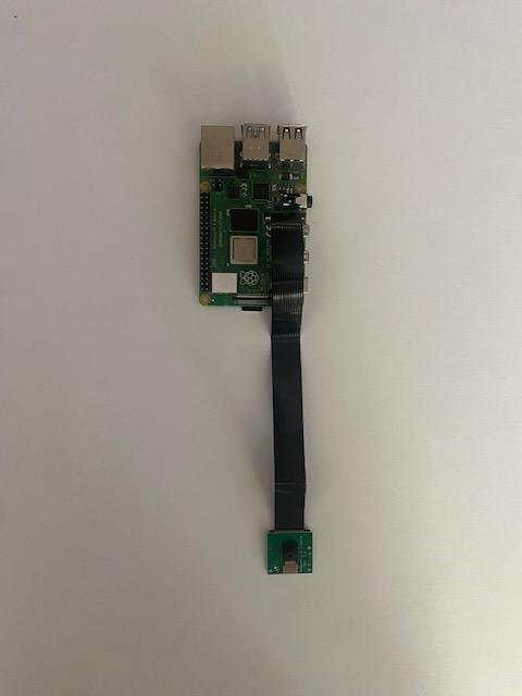
- Connect the camera ribbon to the camera, then to the RPi. There's a black latch that can be pulled on both to connect the ribbon
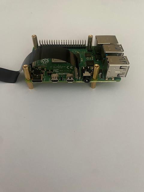
- Attach the copper standoffs to the RPi. The M2.5*10+6 standoffs go through the bottom, and the other standoffs attach from the top
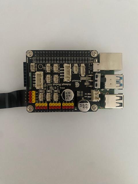
- Use the screws to attach the Robot HAT to the standoffs on top of the RPi
Driver Board and Batteries
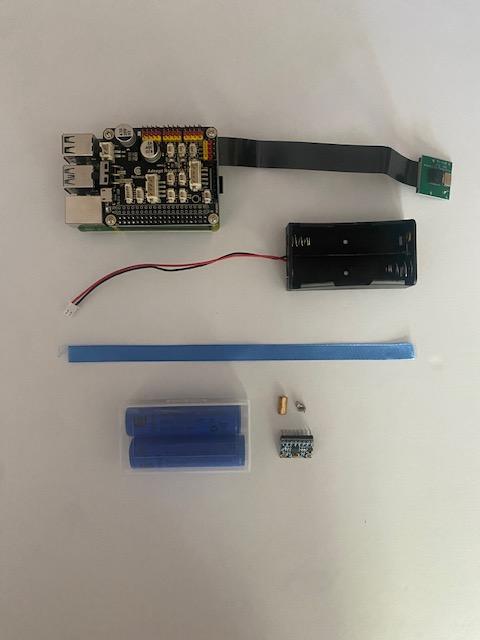
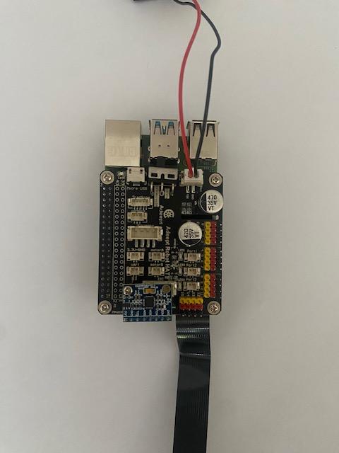
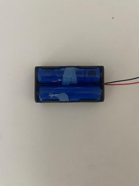
Need:
- 1 x Battery Holder
- 2 x 18650 Batteries
- 1 x Ribbon
- 1 x mpu-6050
- 2 x M2.5*4 Screws
- 1 x M2.5*11 Copper Standoff
Next, we'll get the Pi ready to debug the servos. Ensure the HAT switch is turned off before messing with the batteries.
- Attach the copper standoff on top of the opening in the HAT. Screw in from the bottom of the opening
- Use another screw to connect the mpu to the standoff (bottom of Image 2)
- Connect the battery holder to the HAT
- Place the batteries into the holder using the ribbon to make it easier to remove them later. I double-wrapped the first battery and then put the ribbon under the second
Debug Servos
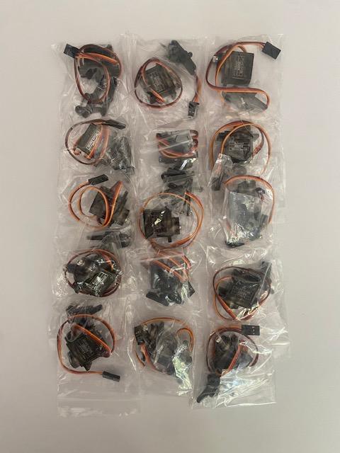
Need:
- 15 x Servos
- Configured RPi
This next step isn't constructive, but it's very important. Your robot can't function correctly without proper alignment.
- Connect each motor to the HAT. Ensure the wires' colors align with those on the pins
- Turn the HAT switch on. After about a minute, a Pi that is properly set up will run a program that sets all the motors to their center alignment
Servo Rockers
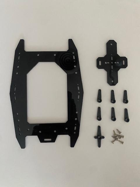
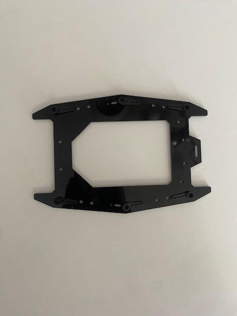
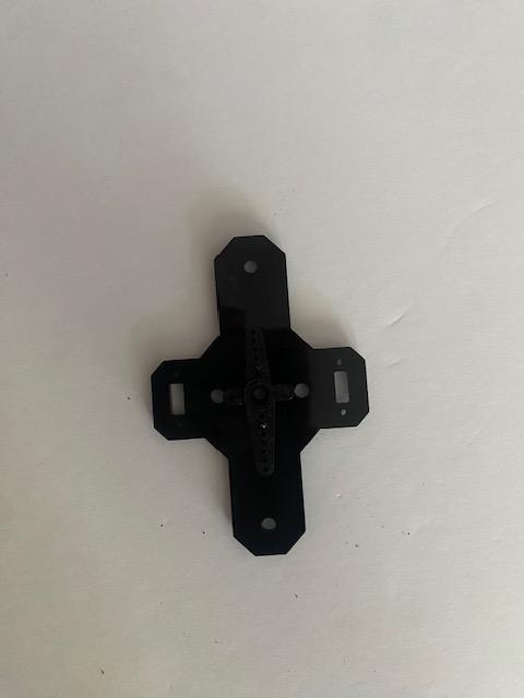
Need:
- 6 x Single Servo Rockers
- 1 x 4-Foot Servo Rocker
- 8 x M1.7*6*6 Screws
- Acrylic Plates Shown
Now we can start the body of the RaspClaws. For the rockers, it helps to slightly insert and remove a screw before actually attempting to attach them.
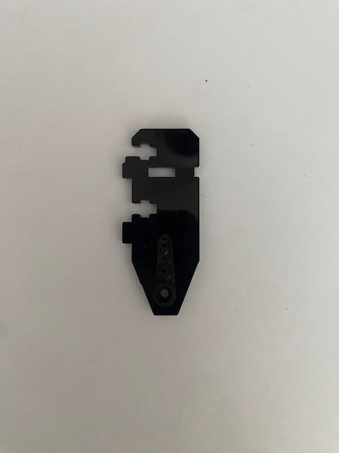
- Use 6 screws to secure the single rockers to the larger plate as shown in Image 2
- Use another 2 screws to fasten the 4-foot rocker to the smaller plate as shown in Image 3
Miscellaneous Plates
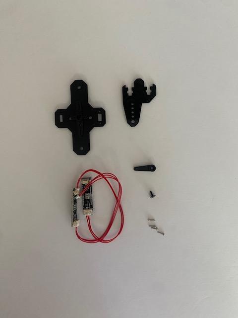
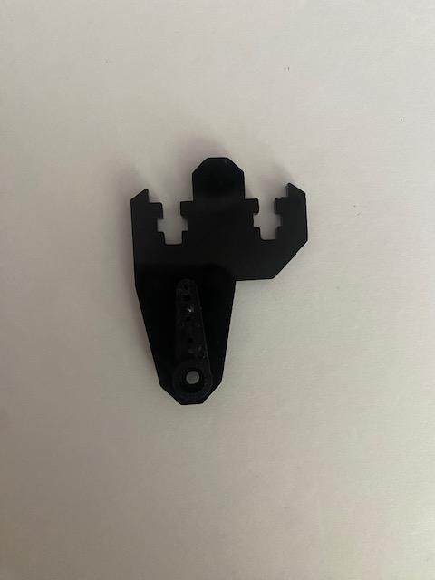
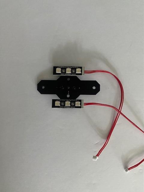
Need:
- 2 x Car Lights
- 1 x Single Servo Rockers
- 1 x M1.7*6*6 Screws
- 4 x M1.4*6 Screws
- Acrylic Plates Shown
Next up is getting a few pieces ready to use later.
- Affix the rocker to the plate with the M1.7*6*6 screw as demonstrated in Image 2
- Secure car lights to either end of the t-shaped plate from the previous step. This takes the 4 M1.4*6 screws
Left Legs
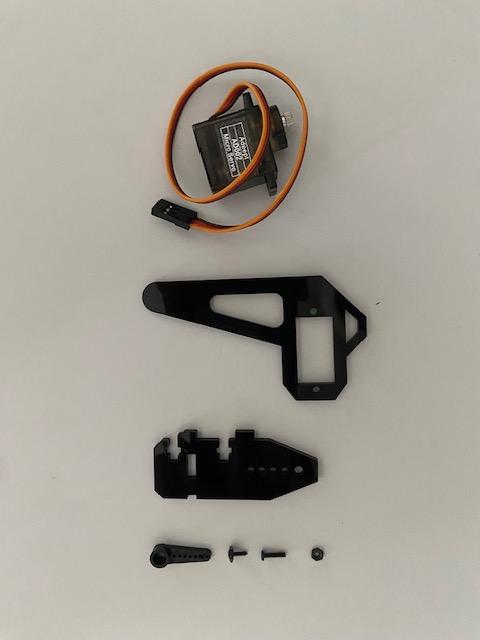
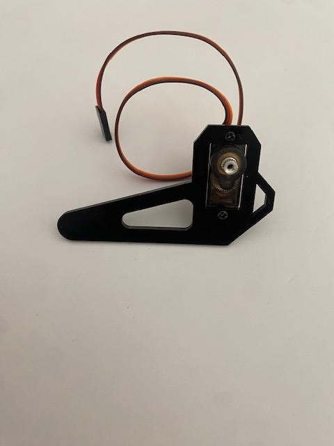
Need:
- 3 x Servos
- 6 x M2*8 Screws
- 6 x M2 Nuts
- 3 x Single Servo Rockers
- 3 x M1.7*6*6 Screws
- Acrylic Plates Shown x 3
Afterward, we can begin preparing the left legs for our robot. Ensure all your servos are at the center of their rotation before beginning.
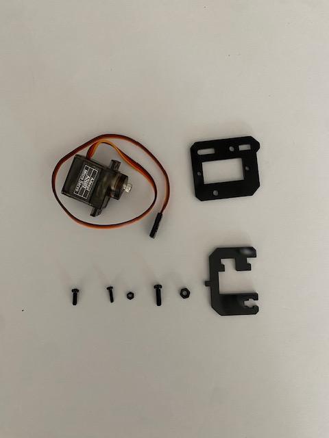
- Using 2 M2*8 screws and 2 nuts, attach a servo to the plate shown in Image 2
- Secure a rocker to the other plate with a 1.7*6*6 screw
- Repeat the previous two directions for a total of 3 plates with a servo and 3 plates with a rocker
Left Legs 2
Need:
- 3 x Servos
- 6 x M2*8 Screws
- 6 x M2 Nuts
- 9 x M3*10 Screws
- 9 x M3 Nuts
- 3 x M2.5*8 Screw
- Acrylic Plates Shown x 3
- Everything from the previous step
The robot's legs are a loaded task, so this is part two.
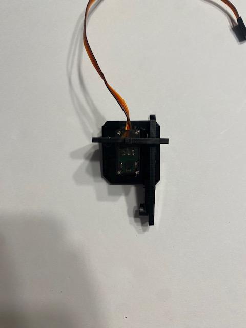
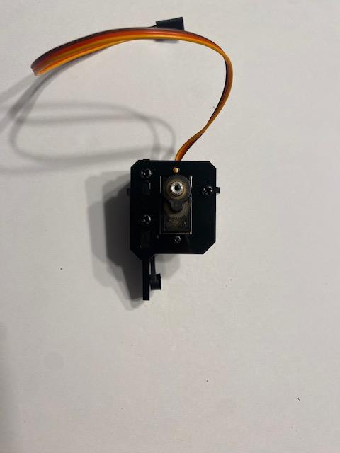
- Using two M2*8 screws and 2 M2 nuts, connect a servo to the plate in the top right corner of Image 1. Refer to Image 4 for orientation
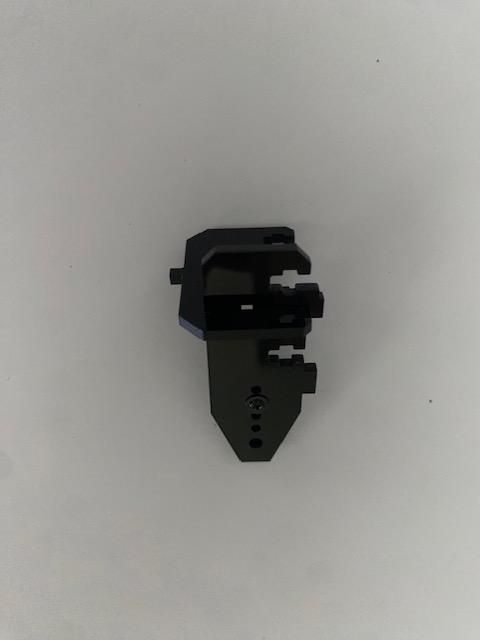
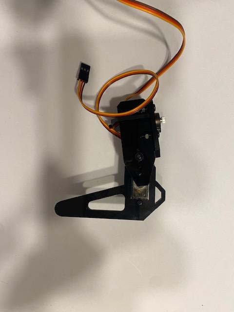
- Combine the other plate in this step with the plate with a rocker from the previous step as shown in Image 2
- Attach that to the plate with a servo from earlier in this step. Use 3 M3*10 screws and 3 M3 nuts to secure everything together. The nuts go into little gaps between the plates
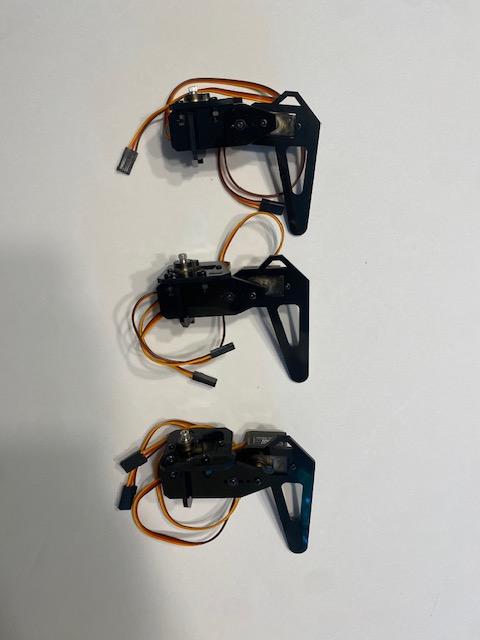
- Combine the completed unit with the servo plate from the previous step using an M2.5*8 screw. Make sure the servos are aligned like Image 5
- Repeat directions 1-4 in this step for a total of 3 left legs
Right Legs
Need:
- 6 x Servos
- 12 x M2*8 Screws
- 12 x M2 Nuts
- 3 x Single Servo Rockers
- 3 x M1.7*6*6 Screws
- 9 x M3*10 Screws
- 9 x M3 Nuts
- 3 x M2.5*8 Screw
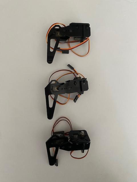
You should be used to making legs by now. The right legs follow the same directions as the left with the parts oriented differently.
- Follow the same directions used to make the left legs, except flip the servos and reverse the acrylic plates
- Repeat for a total of 3 right legs. Image 1 serves as a guide for orientation
Camera -> Plate
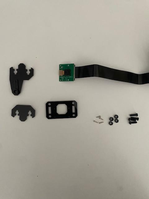
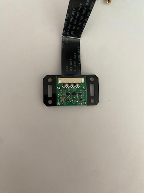
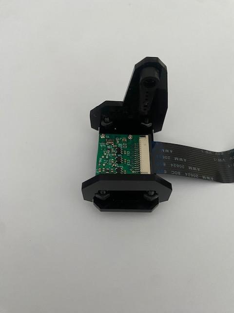
Need:
- 1 x Pi Camera
- 4 x M1.4x*6 Screws
- 4 x M3*10 Screws
- 4 x M3 Nuts
- Acrylic Plates Shown (one from Step 7)
Now we can begin prepping the camera to be mounted.
- With 4 M1.4x*6 screws, fix the camera to the plate shown in Image 2
- Fasten the other two plates to the ends of the camera using 2 M3*10 screws and 2 nuts each. Again, the nuts go into gaps between the plates
Servo -> Camera
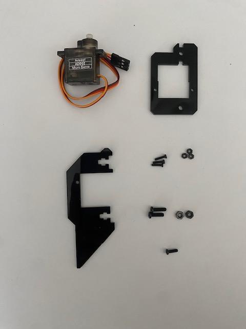
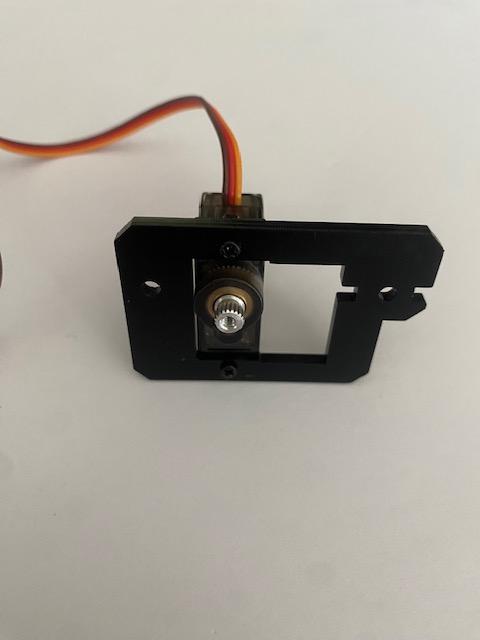
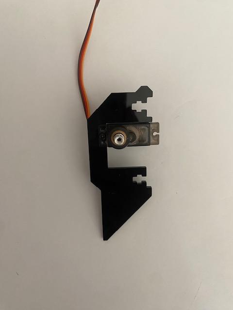
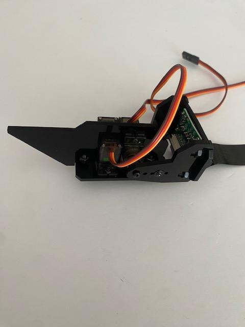
Need:
- 2 x Servo
- 3 x M2*8 Screws
- 3 x M2 Nuts
- 2 x M3*10 Screws
- 2 x M3 Nuts
- 1 x M2.5*8 Screw
- Acrylic Plates Shown
- Camera build from the previous step
This step attaches motors to the camera, making it ready to be mounted.
- Take 1 motor and attach it to the square-shaped plate using 2 M2*8 screws and 2 M2 nuts as seen in Image 2
- Attach another motor to the other plate with 1 M2*8 screw and 1 M2 nut like Image 3
- Place the 2nd plate on top of the 1st and secure with 2 x M3*10 screws and 2 M3 nuts. Refer to Image 4 for orientation
- Take the motor from the 2nd plate and connect it to the rocker attached to the camera. Secure the motor with 1 M2.5*8 screw. Again, refer to Image 4 for orientation
Lights
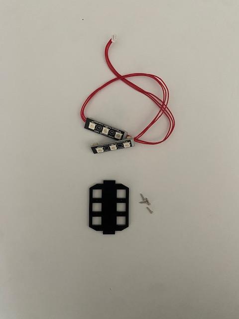
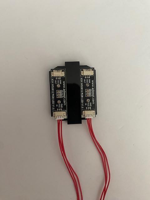
Need:
- 2 x Car Lights
- 4 x M1.4*6 Screws
- Acrylic Plate Shown
You might need a breather, so here's a light step for a part that'll be attached later.
- Place the lights into the openings of the acrylic plate shown
- Attach using 2 screws per light
Attach Pi and Battery Holder
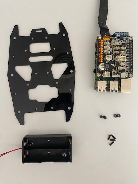
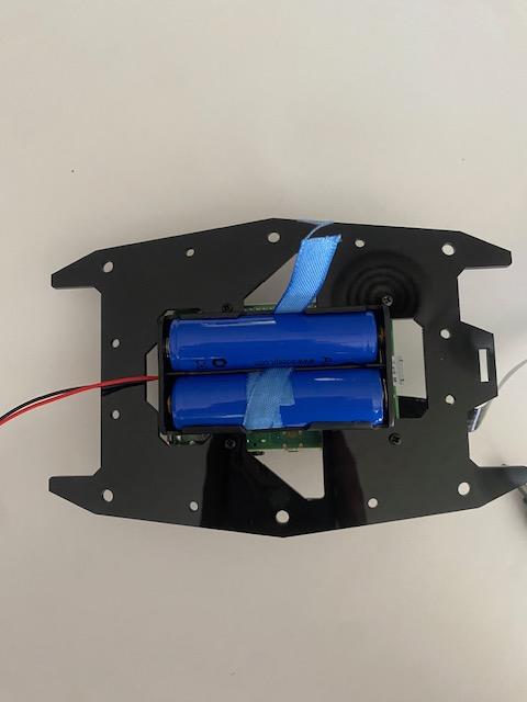
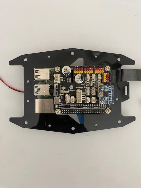
Need:
- 1 x Prepared RPi
- 1 x Battery Holder
- 2 x 18650 Batteries
- 2 x M3*8 Screws
- 2 x M3 Nuts
- 4 x M2.5*8 Screws
- Acrylic Plate shown
We're finally doing some more work on the RaspClaws body.
- Remove the batteries from the holder. Attach the holder to the plate with 2 M3*8 screws and 2 M3 nuts
- Reattach the batteries the same way you did in Step 4, ribbon and all
- Affix the RPi to the reverse side of the plate using 4 M2.5*8 screws that go into the open copper standoffs on the RPi
Attach Legs
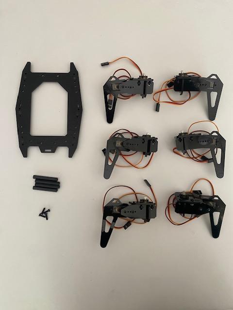
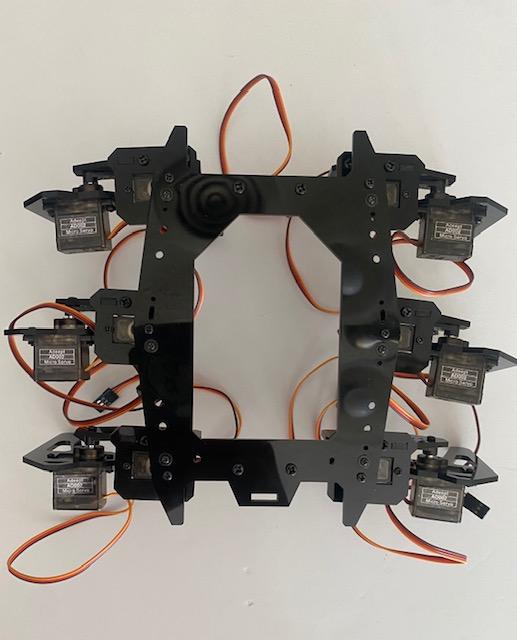
Need:
- 6 x RaspClaws Legs
- 4 x M4*40 Nylon Standoffs
- 4 x M3*8 Screws.
- 6 x M2.5*8 Screws
- Plate from Step 6
Next, we'll prop the body up on its legs.
- Attach 4 nylon standoffs to the holes closer to the center on the ends of the longer side of the plate. The standoffs should be on the same side as the rockers
- Connect the legs to the rockers on the bottom side of the plate. The nub on the plate denotes the front, so keep that in mind when differentiating left from right. WARNING: The legs in Image 3 are reversed. I fixed this later but forgot to take a picture. Refer to the finished robot for the correct placement
- Once you're certain about orientation and your legs are parallel, secure the legs using 1 M2.5*8 screw per leg.
Wire Servos
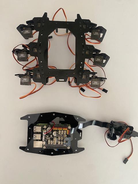
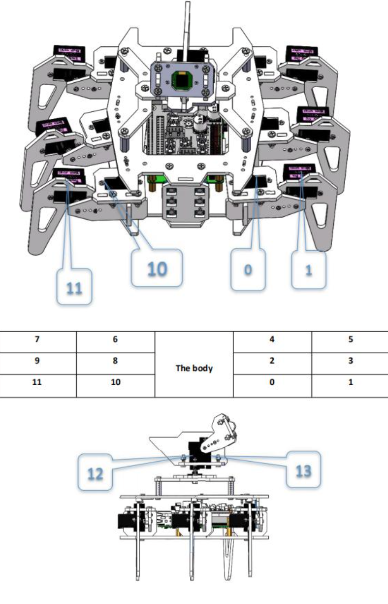
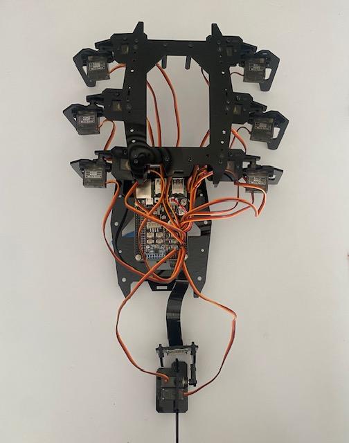
Need:
- Body Build
- RPi Build
- 1 x Zip Tie
Now, we're connecting the two largest parts of our build, starting with wiring.
- Wire all servos to the robot HAT. Refer to Image 2 for the proper pin for each motor
- Connect your lights to the HAT. The incoming wire should always connect to the side of the light with a white bar
- Turn the RPi on and make sure one more time that your servos are oriented correctly
- Organize your wires however you'd like. I wrapped mine in a Zip Tie
Attach Top Plate
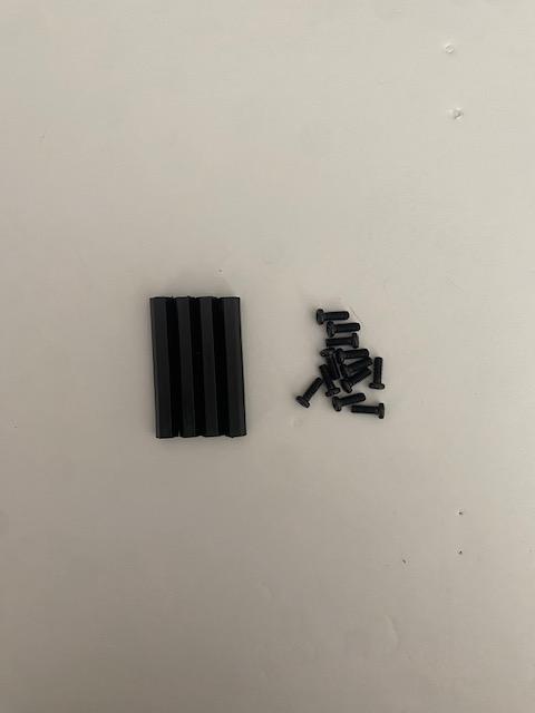
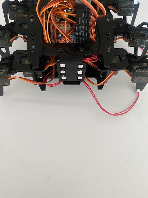
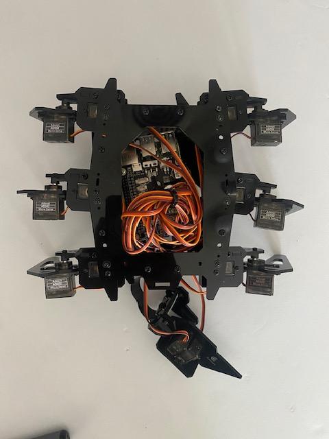
Need:
- 4 x M4*40 Nylon Standoffs
- 12 x M3*8 Screws
- Rectangle Car Light Plate (from Step 13)
Following that, we can mount the leg plate onto the RPi plate.
- Connect 2 nylon standoffs to the right side and 2 nylon standoffs to the left side of the leg plate, similar to Step 15. Each standoff goes directly between two legs (Leg 1 -> Standoff -> Leg 2 -> Standoff -> Leg 3)
- Place the car light into the slots provided on the front side of the plates
- Line the standoffs up with the RPi plate and secure using 8 screws; 4 for the new standoffs and 4 for the ones from Step 15. The RPi should be face-up
Camera Stand
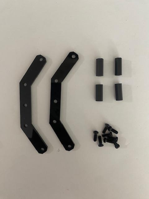
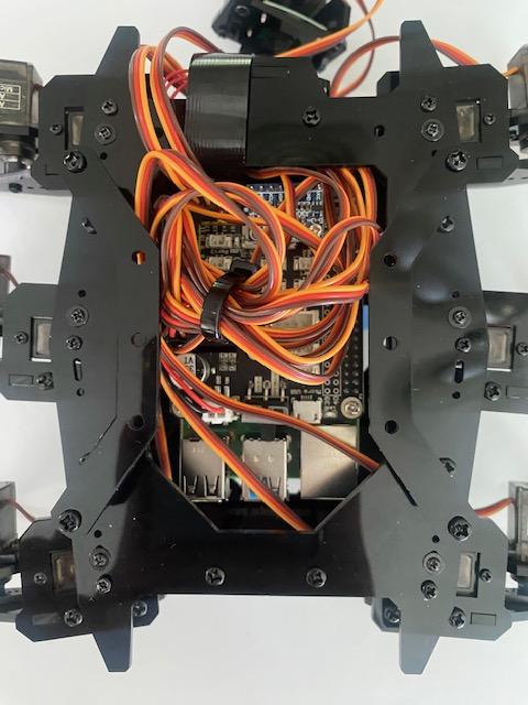
Need:
- 4 x M3*15 Nylon Standoffs
- 8 x M3*8 Screws
- Acrylic Plates Shown
The camera needs a place to sit, which we'll create now.
- Attach 2 standoffs to the opposite ends of each plate
- Attach the plates to the top of the build. They should be oriented like inverted parenthesis (Image 2)
Attach Camera
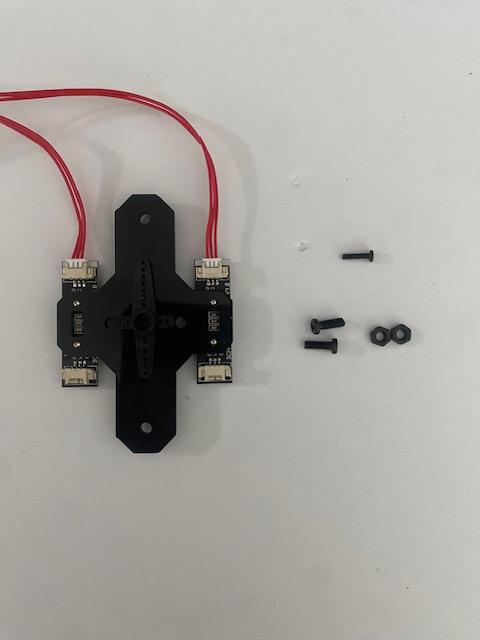
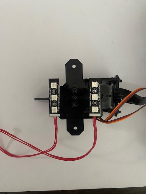
Need:
- 1 x M2.5*8 Screw
- 2 x M3*8 Screws
- 2 x M3 Nuts
- t - Shaped Light Plate
Finally, RaspClaws can get its eyes.
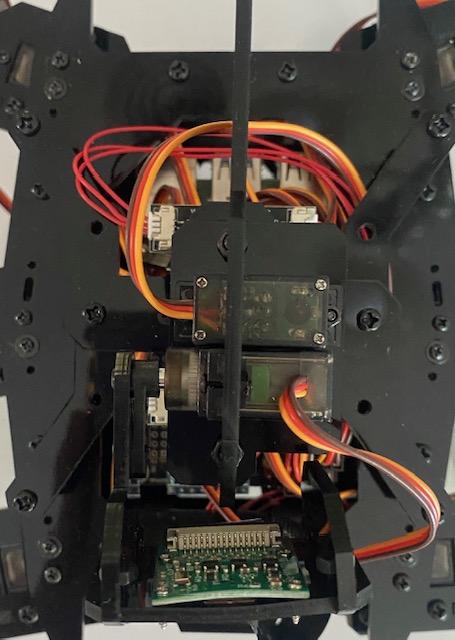
- Connect the available servo from the camera to the rocker from the light plate and secure it with an M2.5*8 screw. The longer sides of the light plate should be perpendicular to the camera (Image 2)
- Using the M3*8 screws and nuts, attach the camera build to the camera stand. The camera should be facing the front of the robot
DONE
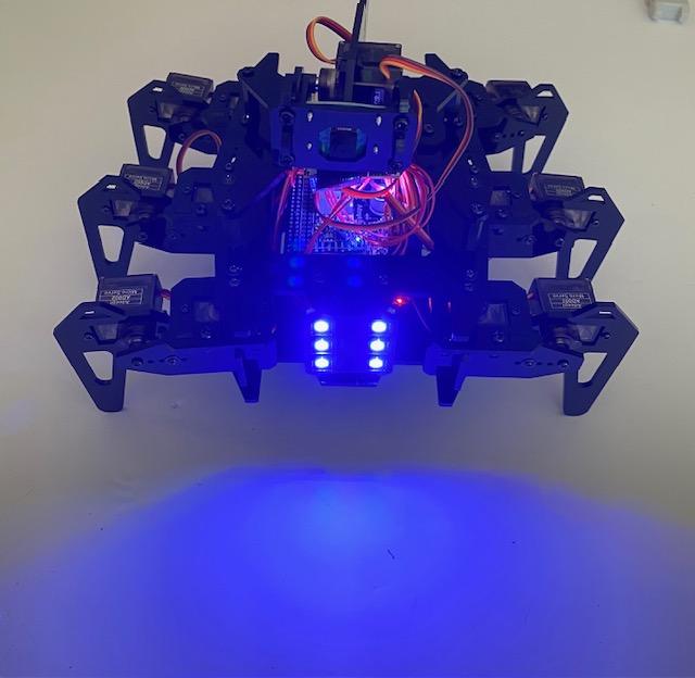
Your RaspClaws is ready to run!
Adeept provides a web page for controlling your robot using your keyboard. Enter "[PI_IP_ADDRESS]:5000" into any browser to reach the page.
Ex) 123.456.7.890:5000