RGBLAMP.IO
.gif)

.gif)
Hey everyone WHAZZUP!
So here's my DIY RGB Desk Lamp/RGBLAMP. IO which is powered by an ESP12F Module and costs less than 20$. It has an internal lithium-ion battery and can be controlled via a web app.
My goal was to build a cheap Philips hue lamp alternative that has basic features like RGB LED Toggle and brightness control feature in less than 20$, so I made this Lamp!
This Instructables is gonna be about the building process of this lamp, how I made its PCB, the SMT process of this board, and the coding part which utilizes a simple web server for RGB control.
It's not very complicated and if you are familiar with ESP8266 MCU, it's basically a minimal ESP8266 with 18 WS2812B LEDs.
Let's get started!
Supplies
These are the things that we need for this built-
Electronics components-
- ESP12F x 1
- 10K 0805 x 5
- AMS1117 x 1
- 1uF 1206 x 1
- 10uF 1206 x 1
- 10uF Aluminium Electrolytic Capacitors x 1
- WS2812B x 18
- USB Micro Port x 1
- M7 Diode x 1
- 100nF 0603 x 18
- JST Connectors Male and Female set x 2
- Rocker Switch 6A DPST x1
- Lithium Cell/ battery 2600mAh 3.7V x 1
- Tic Tac Switch x 1
Mechanical Parts
- Body x1
- Diffuser x1
- 3D printed Base x 1
- Solder paste
- Hotplate
PCB PLANNING-SCHEMATIC-ORDERING
.gif)
.gif)
So the first thing that I did was, I prepared a basic schematic in which I placed 18 WS2812B addressable LEDs and connected them with a minimal ESP12F or 12E setup. (check the Schematic attached for this)
I also added an AMS1117 circuit for stepping down the 5V from USB or 3.7V from the battery side as the ESP12F is 3.3v tolerant and 5V will instantly burn the board. I didn't make any breadboard prototype for this setup as I previously have made similar projects, for example, these RGB glasses.
https://www.instructables.com/RGB-Glasses/
They also have the same setup, everything is the same except the number of LEDs and the mechanical fittings and shape.
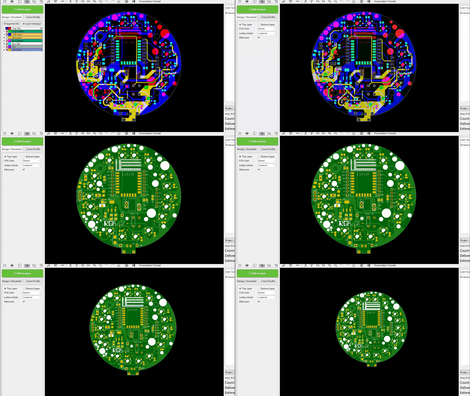
In the PCB editor, I put WS2812B LEDs in a Ring sequence and added the ESP12F at the middle and AMS1117 at one side. After Finishing the PCB and checking the whole board thoroughly, I exported the Gerber data and open it in the DFM software by the next PCB which you can download and use from here-
⭐Free PCB File checker: https://www.nextpcb.com/nextdfm.html?code=ArnovSh...
DFM software is basically a PCB Checker which you can download to check your PCB or Render your PCB before sending it for Manufacturing.
The DFM software can quickly open Allegro, Altium, Protel, PADS, Gerber, and other files for analysis. For example, when it finds out the open circuit it can repair it by editing the function.
In this software, I uploaded each Gerber layer and verify them one by one to spot any mistakes.
After checking the board thoroughly, I clicked on the render option to check out the rendered version of this PCB in green solder mask... After doing all the checking and rendering stuff, I placed the order straight from this software.
I Used NextPCB PCB Service for this project- https://www.nextpcb.com/?code=ArnovSharma check them out if you need great PCB service for a low cost!
⭐Register to get free $100 coupons: https://www.nextpcb.com/register?code=ArnovSharma
I received PCBs from NextPCB in a Week and working on its SMT Process.
Downloads
PCB Assembly

.gif)
.gif)
The assembly process of this board is mostly SMD components that require solder paste instead of normal solder wires and a hotplate or a reflow gun.
also, Hot reflow gun can destroy SMD LEDs as the SMD LED's outer surface is made from plastic, and supplying heat from the top might melt the outer surface so it's wise not to use this method for plastic parts. Instead of a reflow gun, I used a DIY Hotplate for Reflow.
I previously made an SMD Hotplate from an Irons element, it works just like a commercial hotplate but a normal hotplate can be used here or you can get creative and use a Frying pan and sand for Reflow soldering!
Hotplates heat the PCB from the base side which melts the solder paste so the upper surface of the led is not directly in contact with heat so this method is best for soldering LEDs.
- I first added the solder paste to ws2812b led pads and this process took time and effort as I didn't order stencil this time, and adding solder paste only one to each pad is such a pain.
- after adding the solder paste to each pad, I placed ws2812b LEDs on its assigned pads one by one in the right order.. placing them in the right order in reference to silkscreen is crucial as they won't work when you connect them wrong so be extra careful with this setup! after adding LEDs
- I added 100nf capacitor to its assigned pads one by one, these capacitors can be placed in any orientation so we don't need to worry about the polarity.
-
after this, we just need to put the PCB on the hotplate and let it heat for few mins.
just let the solder paste melts and remove the PCB in few seconds when the solder paste melts completely. -
The result will be a PCB with 18 WS2812B LEDs soldered onboard.
Now in order to test whether the LEDs are soldered properly, I added 3 wires to the led VCC, GND, and DATA pins connected this led ring PCB with a pro micro board, and run a simple NEOPIXEL test sketch.
after confirming that the PCB has been reflow properly, I added solder paste to every component pad and then added all the comments on their assigned place one by one according to the schematic.
(ESP12F, Resistance, AMS1117, capacitors, etc)
I added the PCB to the hotplate and let the solder paste melt (FUN FACT- Solderpaste that I have melts between 190-210°C but there are other Solderpaste that has a lower or higher melting temperature).
The result was a complete RGBLAMP board with ESP12F setup which is now almost ready to be flashed. But before that, I added 2 connectors for the battery and rocker switch along with a tic tac switch which is for resetting the ESP12F, and for that, I just use a good old soldering iron!
The next step is to flash the ESP12F and check whether this circuit is working or not!
ESP12F Programmer


For Programming ESP12F, we can use an FTDI module but there's also exist a better and easy method that required only a NodeMCU board.
I previously made a PCB which is an ESP12F Programmer board that contains a NodeMCU and few header pins. basically, we just need to connect any minimal ESP12F Setup with NodeMCU in this config.
We first pull down the enable pin of NodeMCU to GND which turns off the ESP12F on NodeMCU, we can just hook an extra esp12f setup and use NodeMCU's CP2102 chip to flash that. I already have made Instructables on this topic so you can check that out from here-
https://www.instructables.com/Program-ESP8266-With...
In the RGB LAMP PCB, I connected all the programming pins which are VCC, GND, RST, GPIO0, TX, and RST to a CON6 header pin.
For programming, we can directly plug the NodeMCU Programmer PCB onto the RGBLAMP's PCB CON6 Header Pin. It's a clever method to use as because of this external programmer, we don't need to add FTDI Chips on ESP12F setup and we can make smaller PCBs and for programming them we just breakout 6 important pins and connect our external programmer with it.
CODE and Basic Testing
.gif)
.gif)
For Uploading code,
- first, plug the NodeMCU programmer with the RGBLAMP's PCB
- change the wifi credentials
- select the Nodemcu as the mainboard in the tool option with the right port, and upload the code.
after uploading the sketch,
- open the serial monitor at 115200 baud rate and hit the reset button.
- you will see the IP address of the ESP2F setup.
- copy the IP address and open it in your browser.
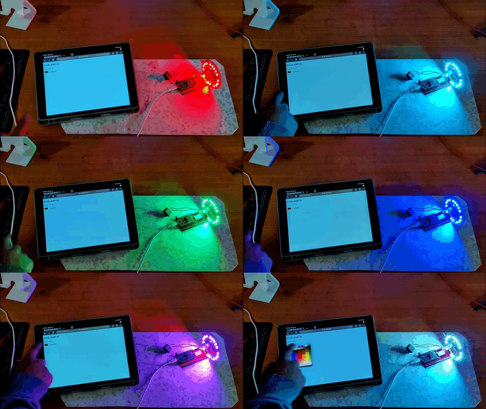
- you will see the RGB LAMP. IO web server
The web server is not aesthetically appealing but it will let you toggle any color by clicking on the color palette and adjust brightness.
Now let's move on to the next part which is the final assembly!
Downloads
Final Assembly


.gif)
For the main body of this lamp, I used a metal 50W Bulb Body which comes with a diffuser and can be bought from online sources.
As for the base for the Metal body, I designed and then 3D printed a base on which I have mounted a lithium-ion battery pack and an ON-OFF rocker switch and that is pretty much the base and body of our lamp.
The Next step is to edit the metal body according to the PCB.
For starters, our PCB will be screwed on the top part of this metal lamp body, I made mounting holes in the PCB design but this body doesn't have a cavity or cutout for the USB charging port, so I marked the cutout length according to the USB size and use a hacksaw to cut that part out. I also made a similar cutout in the diffuser body.
After this, I drill holes in the metal body for the switch and battery wire with a drill machine and that is pretty much the editing part. we start the main and final assembly by first adding electrical tape to the metal body top part as our PCB might get shorted when placed on top of an exposed metal surface and that won't be a good thing so I cover the exposed metal part with electrical tape. after that, I placed washers or spacers on mounting holes to lift the PCB a little bit from the metal surface and used screws to mount the PCB on the base permanently.
now we just need to add a battery and switch connector onto this PCB.
connect the male connector with its female connector on PCB and solder its wire on the battery and then redo this for the switch connector.
In the end, just close the lower part of the body by pushing the base on its locking position and add a diffuser onto this lamp in the right order and the setup is completed!.
RESULT
.gif)

CODE is already loaded on this RGB LAMP PCB so we just need to turn on this device by toggling the rocker switch present on the lower base and open this lamp's web server.
- Click on the Black rectangular block
- Select any color from the color chart and BANG
WATCH THE VIDEO-
Leave a comment if you need any help!
Huge thanks to the next PCB for supporting this project, check them out if you need great PCB service at a low cost!