RGB LED Project : Simple Display Box
by jasminel4636 in Circuits > LEDs
357 Views, 0 Favorites, 0 Comments
RGB LED Project : Simple Display Box
Make a simple display box!
This is a project modify by https://www.instructables.com/id/RGB-LED-Color-Mixing-With-Arduino-in-Tinkercad/
Prepare the Necessary Material

Prepare the necessary material :
1. RGB LED
2. 5 Jumper wires
3. Arduino Uno R3
4. Breadboard
5. 3 Resistance
Build the Circuit

Set the LED RGB where you want to put on the breadboard. Connect the wires to GND on the Arduino and the negative on the breadboard.
Connect to RGB LED
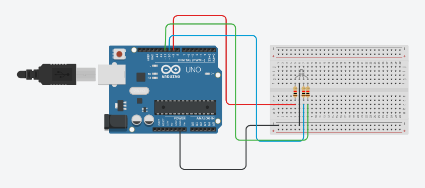
The RGB LED has a cathode at its second leg, so we can use another wire to connect with them.
Add three resistances for three LED pins. (Each pin is for red, green, blue light)
Add three wires in each pin on RGB LED to connect to a different pin on Arduino. (9, 10, 11)
Enter the Code

void setup()
{ pinMode(11, OUTPUT); pinMode(10, OUTPUT); pinMode(9, OUTPUT); }
void loop() { analogWrite(11, 255); analogWrite(10, 0); analogWrite(9, 0); delay(1050); //改 Wait for 1050 millisecond(s) analogWrite(11, 255); analogWrite(10, 255); analogWrite(9, 102); delay(1050); // 改Wait for 1050 millisecond(s) }
Arduino Code
https://create.arduino.cc/editor/jasmine324/455b3908-8ac6-4ac4-bc6c-96a42b871c19/preview
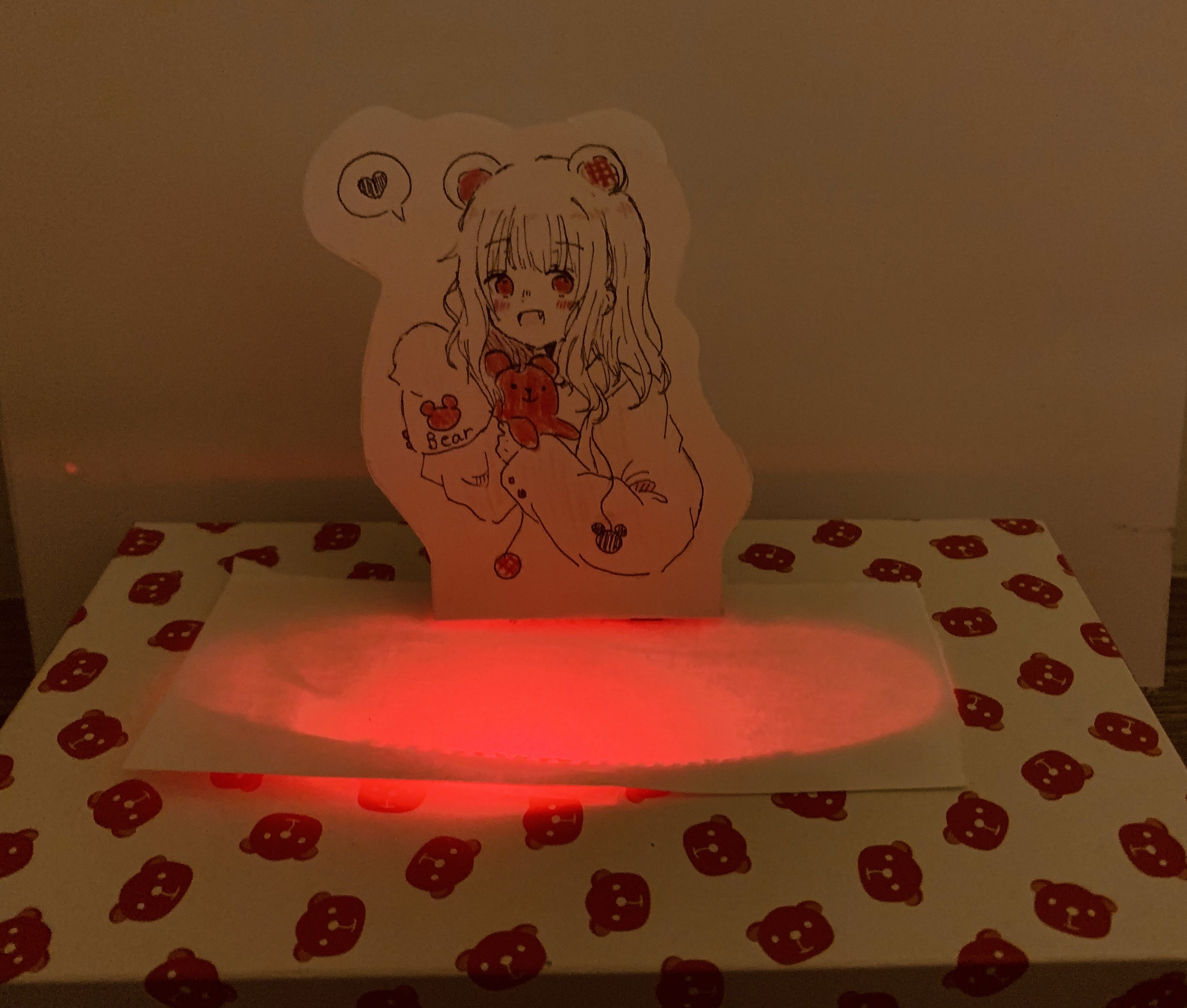
Make some decorations.
Finish!