RGB LED Interfacing With Arduino
by Utsource in Circuits > Arduino
2915 Views, 2 Favorites, 0 Comments
RGB LED Interfacing With Arduino

Hi guys in this instructables we will learn how to use RGB LED with Arduino and make the LED glow in different colors.
Things You Need

.jpg)

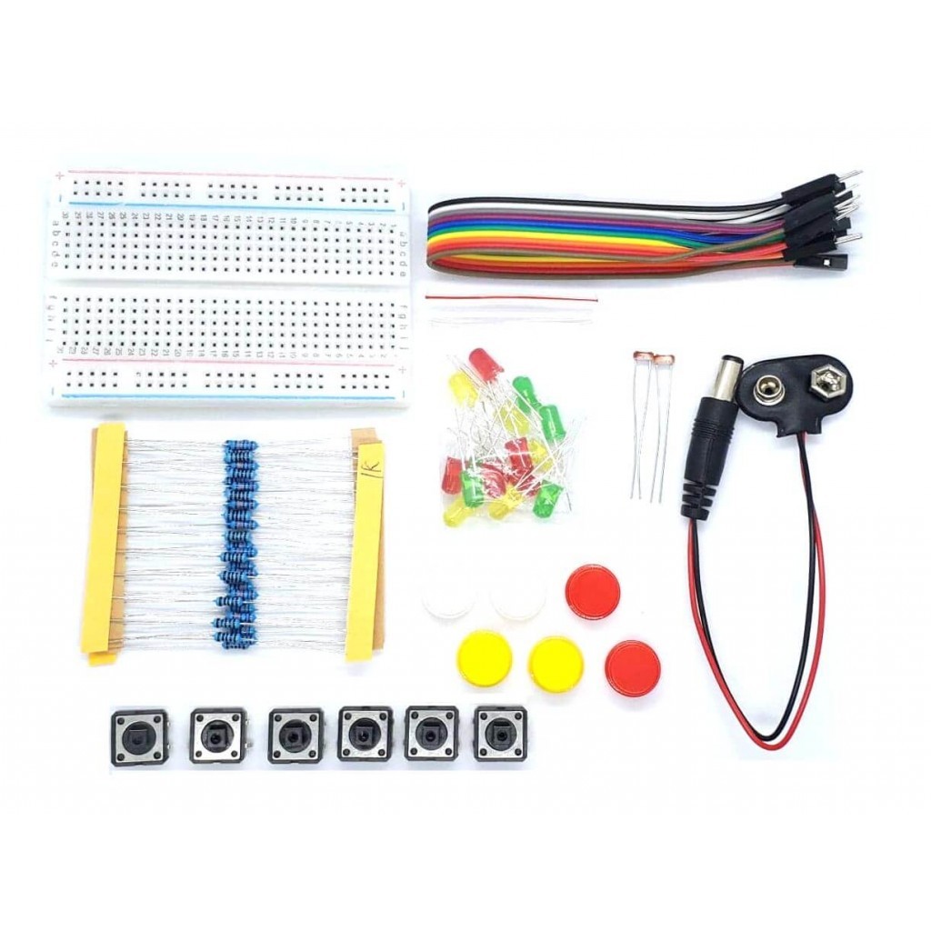
For the instructables we will need following things :
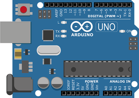
Arduino uno
resistors
Breadboard
Jumpers
RGB LED
Basics of RGB LED
.jpg)


The RGB LED will have four pins as shown in figure.
PIN1: Color 1 negative terminal in common anode or color 1 positive terminal in common cathode
PIN2: Common positive for all three colors in Common anode type or common negative for all three colors in common cathode type RGB LED.
PIN3: Color 2 negative terminal or color 2 positive terminal
PIN4: Color 3 negative terminal or color 3 positive terminal
So there are two types of RGB LEDs, one is common cathode type (common negative) and other is common anode type (common positive) type. In CC (Common Cathode or Common Negative), there will be three positive terminals each terminal representing a color and one negative terminal representing all three colors. The internal circuit of a CC RGB LED can be represented as below.
Common Cathode RGB LED
In Common Cathode type, If we want RED to be On in above, we need to power the RED LED pin and ground the common negative. The same goes for all the LEDs. In CA (Common Anode or Common Positive), there will be three negative terminals each terminal representing a color and one positive terminal representing all three colors.
The internal circuit of a CA RGB LED can be represented as shown in figure.
Common Anode RGB LED
In Common Anode type, if we want RED to be on in above, we need to ground the RED LED pin and power the common positive. The same goes for all the LEDs.
In our circuit we are going to use CA (Common Anode or Common Positive) type. If you want to connect more RGB LEDs, say 5, then you need 5x4= 20 PINS usually, but we can reduce this PIN usage to 8 by connecting RGB LEDs in parallel and by using a technique called multiplexing.
Circuit Diagram
.jpg)
Follow the circuit diagram shown in the image and connect everything According to the schmatics.
Coding Part
.jpg)
A RGB LED is a combination of three different LEDs RED LED, GREEN LED & BLUE LED. so if you want any color you can mix up few percentage of red green and blue color to get uo & for that we will use analogWrite to use whatever the value of each color you want.
So copy the following code & Upload it to arduino :
void setup()
{
pinMode(9,1); //red led
pinMode(10,1); //green led
pinMode(11,1); //blue led
}
void loop()
{
analogWrite (9,255);
analogWrite (10,0);
analogWrite (11,0);
delay(1000);
//Setting 9 to 255 will make it glow red color
analogWrite (9,255);
analogWrite (10,255);
analogWrite (11,255);
delay (1000);
//Setting red,green & blue to 255 will light up as white
analogWrite (9,255);
analogWrite (10,0);
analogWrite (11,255);
delay (1000);
//Setting red & blue to 255 will make it glow purple
analogWrite (9,255);
analogWrite (10,0);
analogWrite (11,255);
delay (1000);
//Purple color
}
LED Output


So finally i Uploaded my code to arduino board and RGB LED is working as we expected.