RGB HexMatrix | IOT Clock 2.0
by Mukesh_Sankhla in Circuits > LEDs
4548 Views, 58 Favorites, 0 Comments
RGB HexMatrix | IOT Clock 2.0
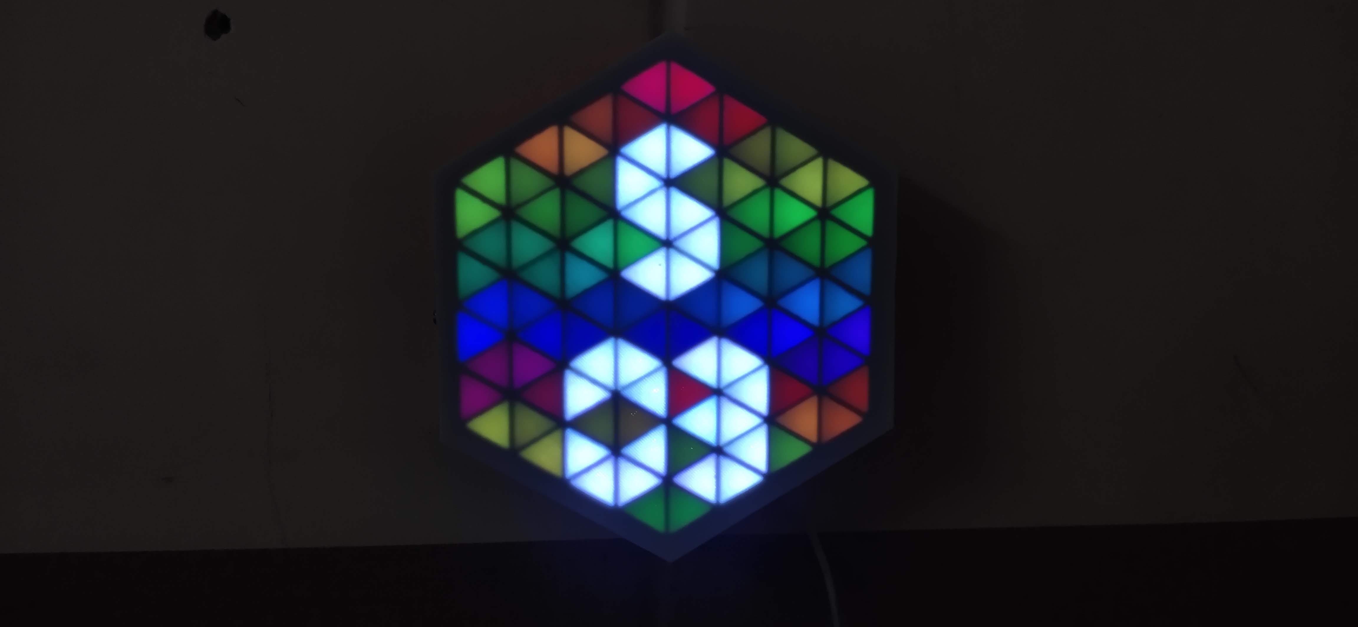
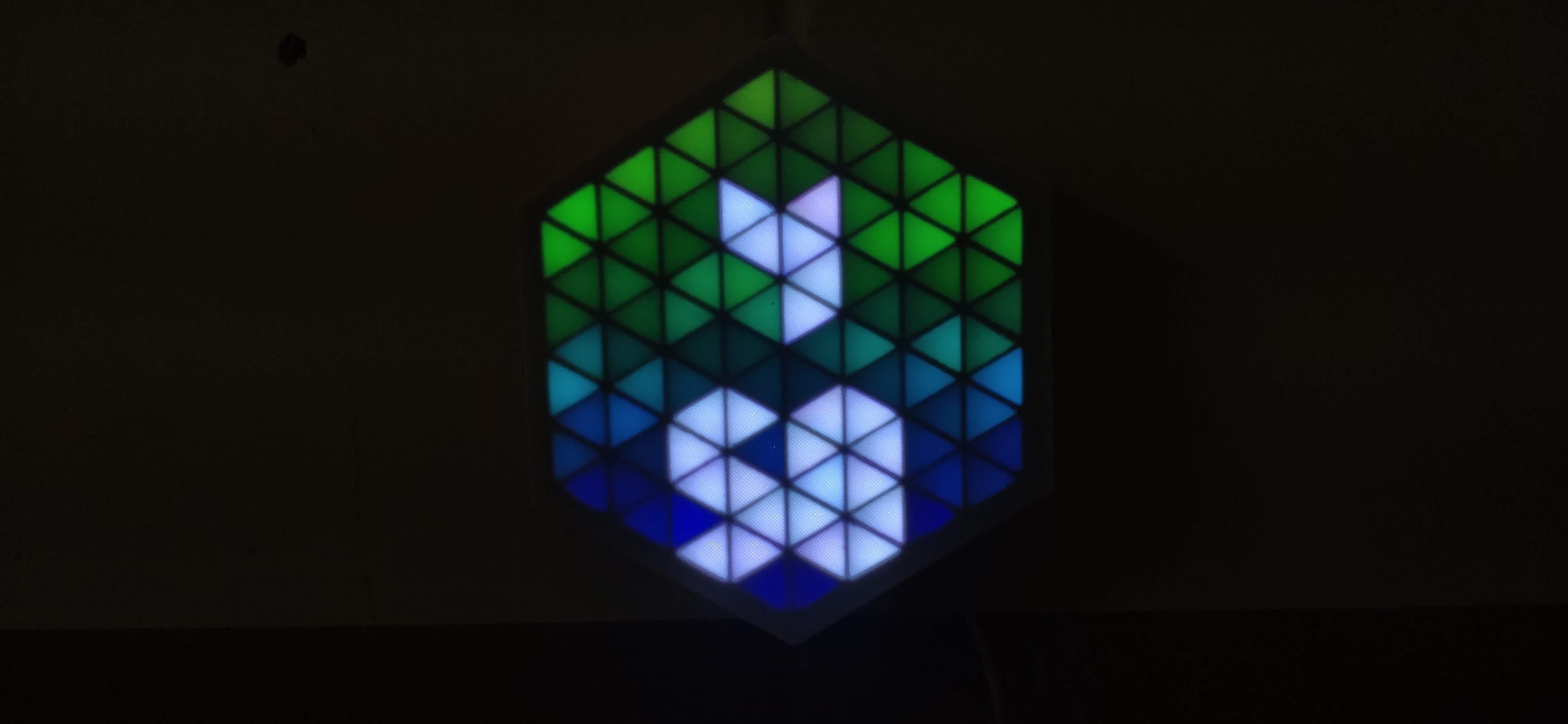
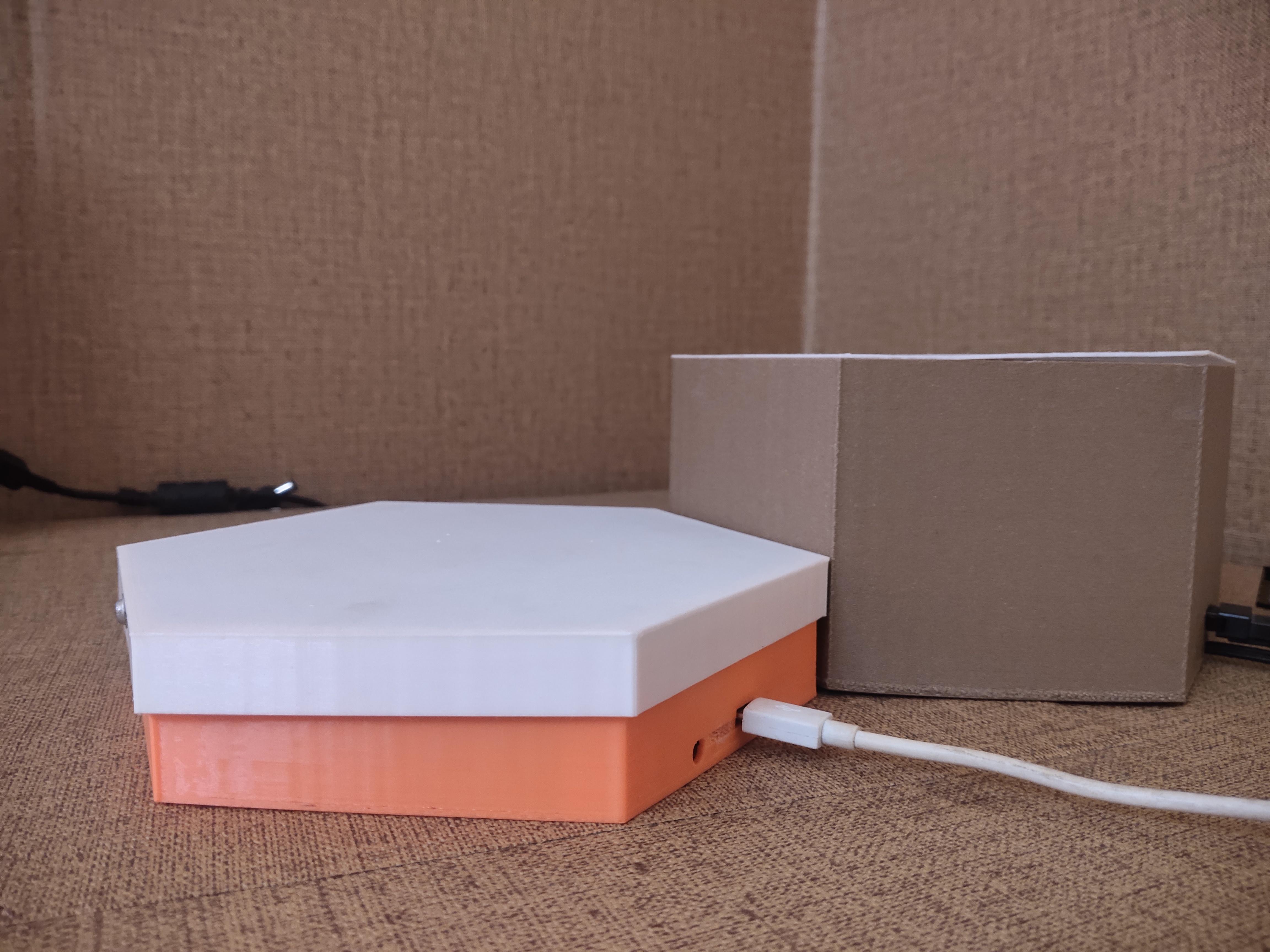
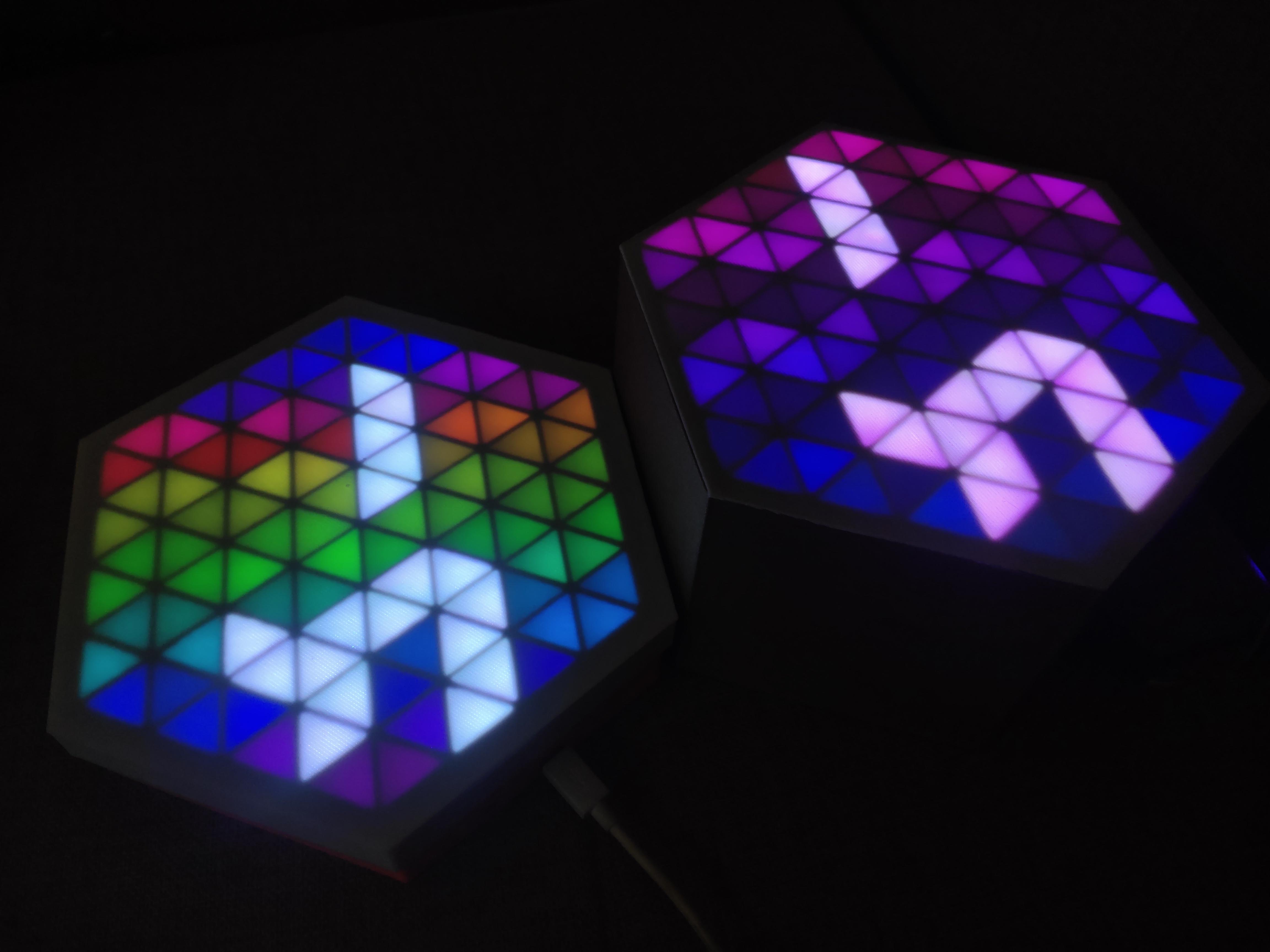
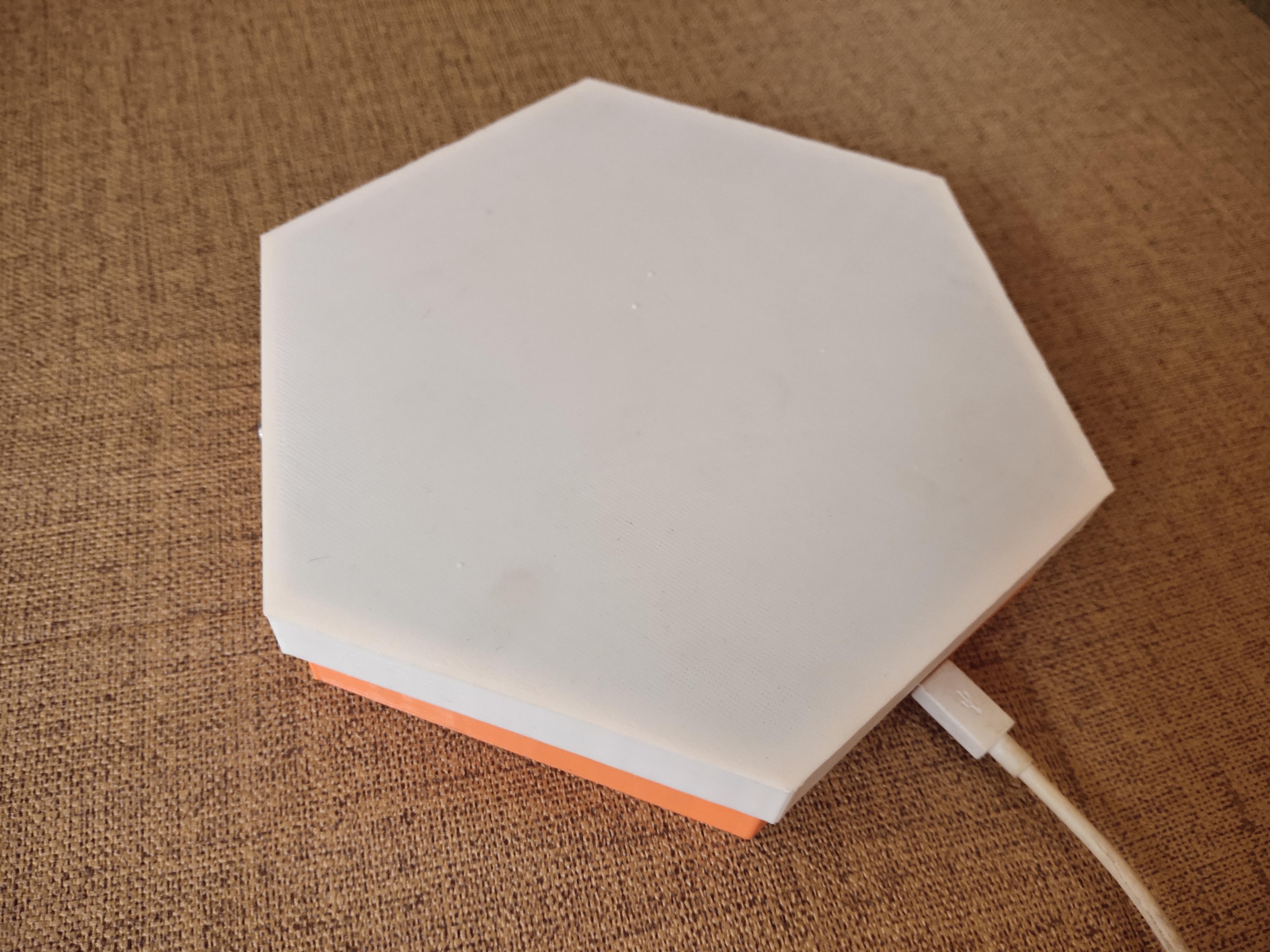
HexMatrix 2.0 is a upgraded of previous HexMatrix. In the previous version we have used WS2811 LEDs by that the HexMatrix became heavy and thick. But in this version of matrix we are going to use custom PCB with WS2812b LEDs which made this matrix to be 3 cm thin.
Supplies:

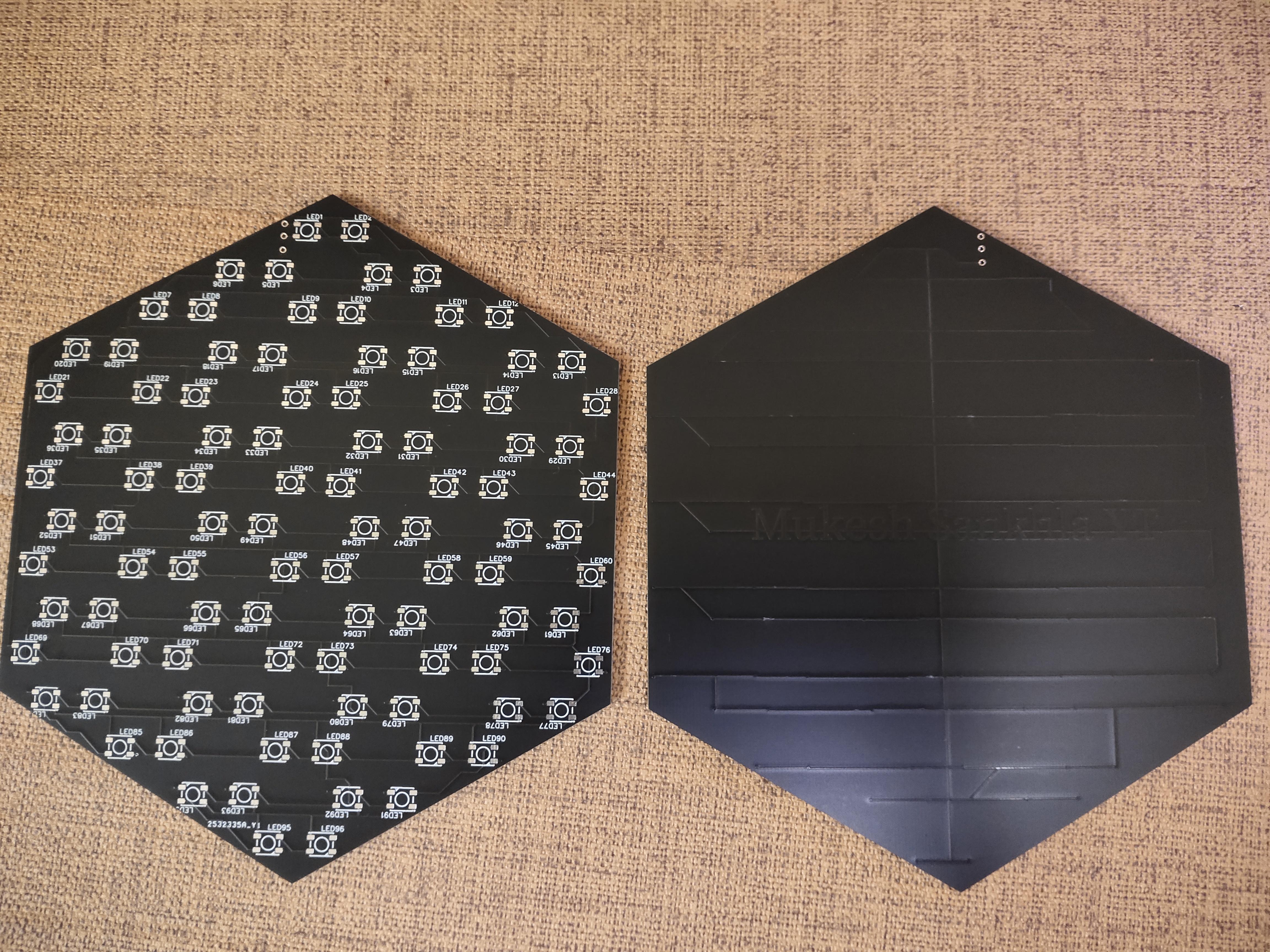
- PCB Click for Gerber file
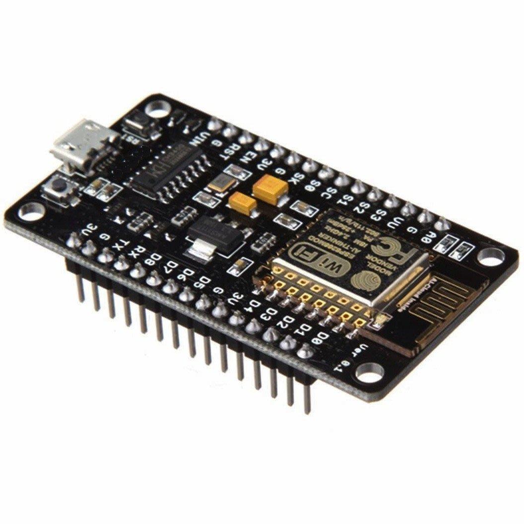
- NodeMCU(ESP8266)
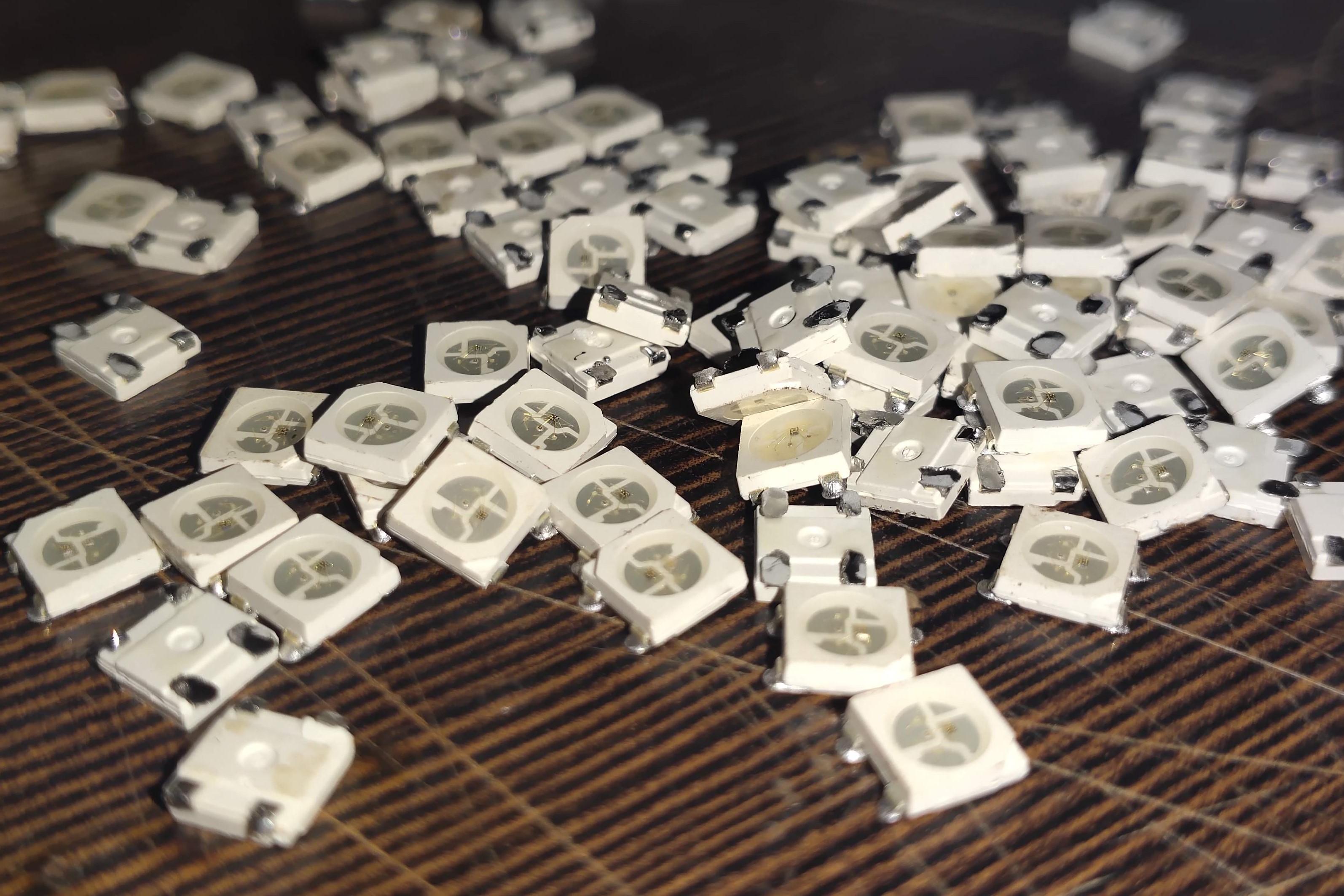
- WS2812B LEDs
- 5V 2A micro USB adapter
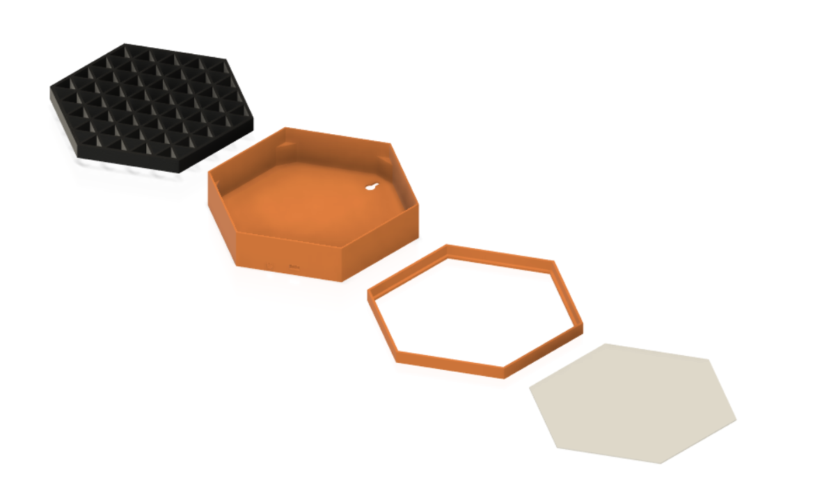
- 3D Printed Parts
3D Printing:
.png)
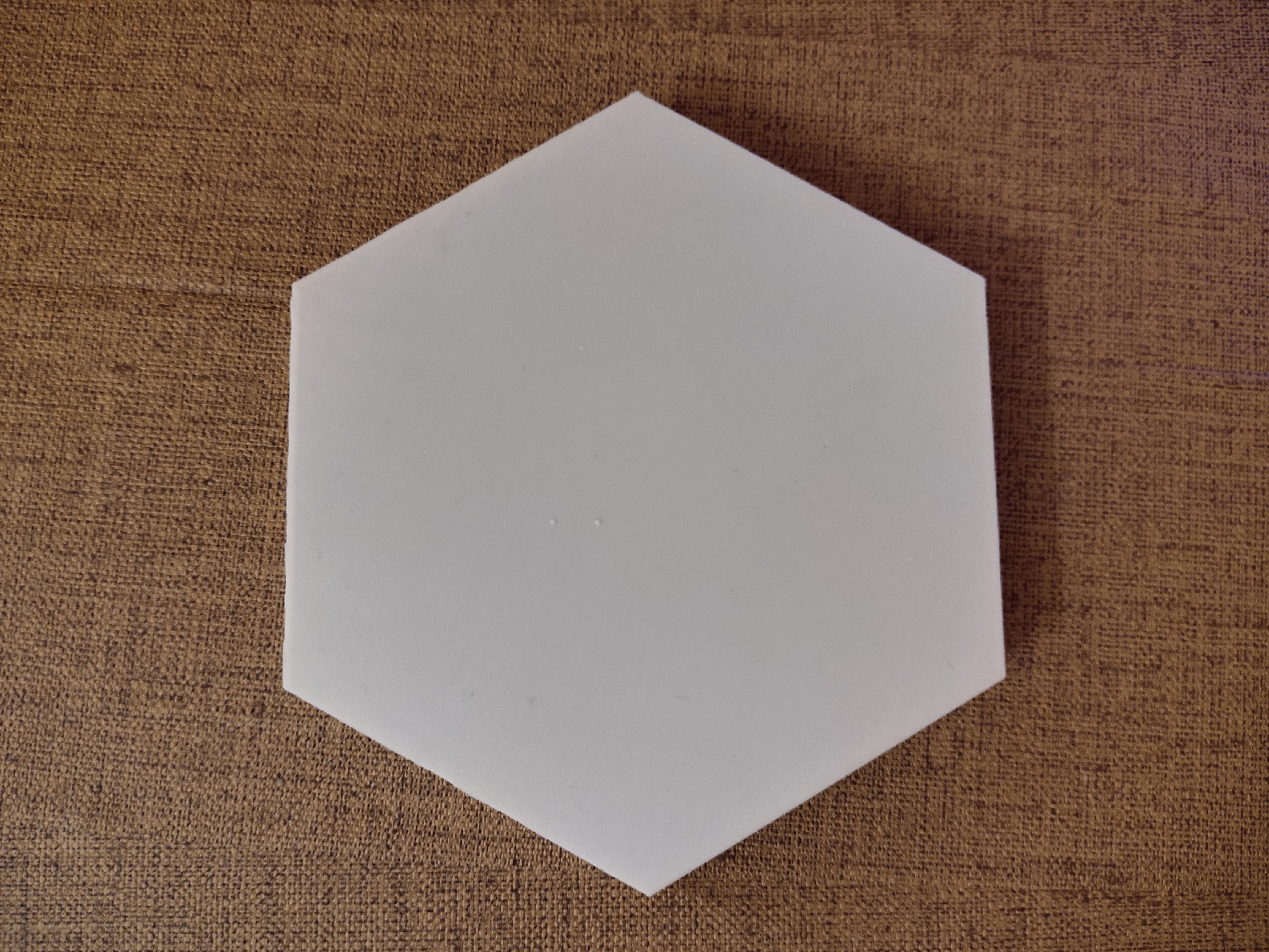
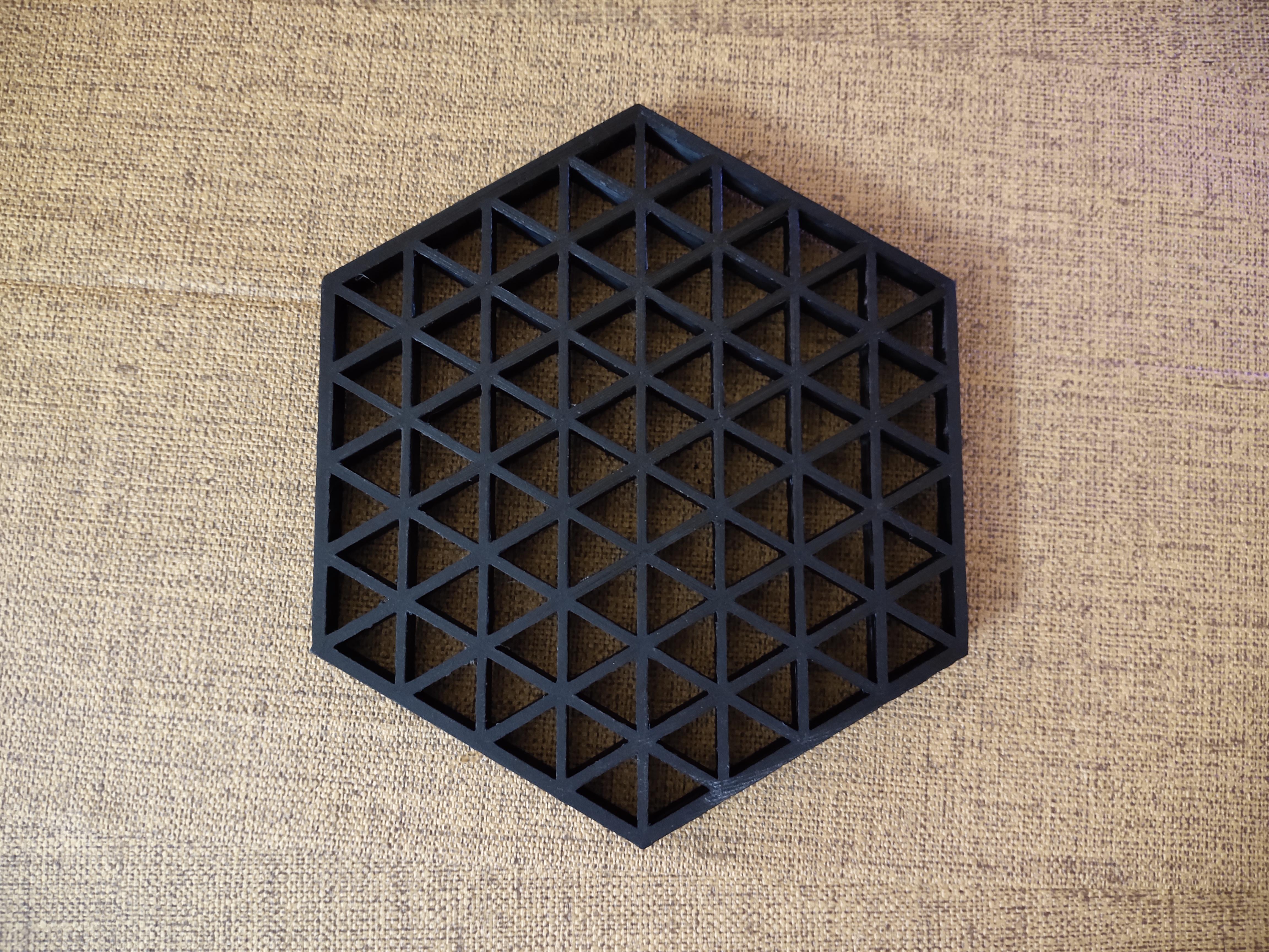
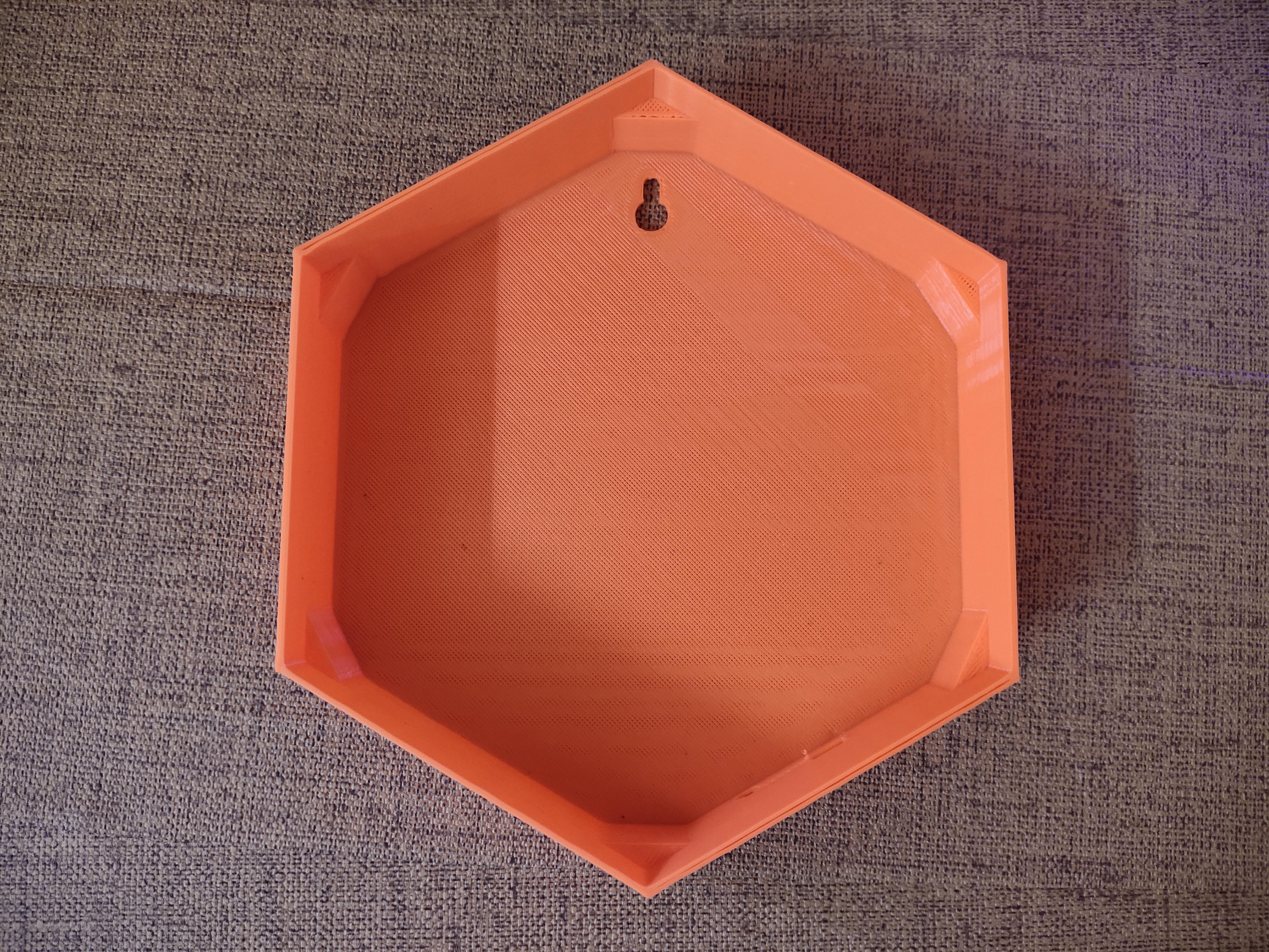
- Click for STL files
- 3D Print all the 3D models, make sure to print the screen in white PLA.
- The design I made is for hanging on the wall you can modify as per your requirement in Fusion360 Fusion360 file.
Circuit Connection:
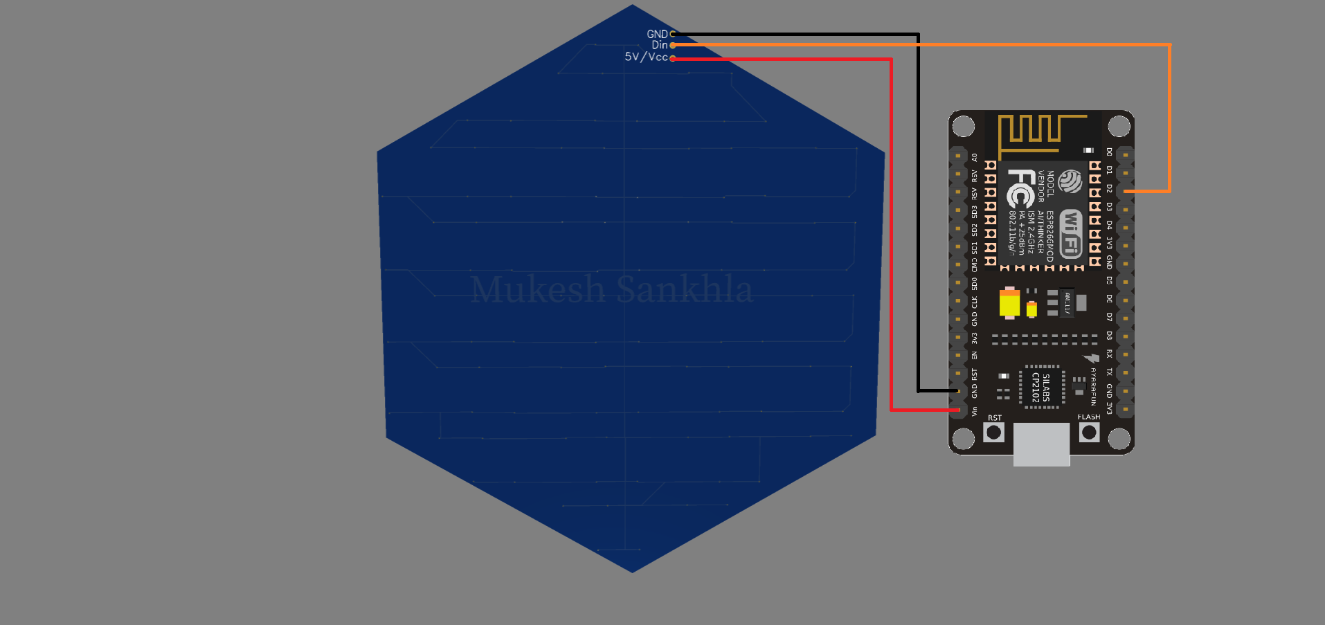
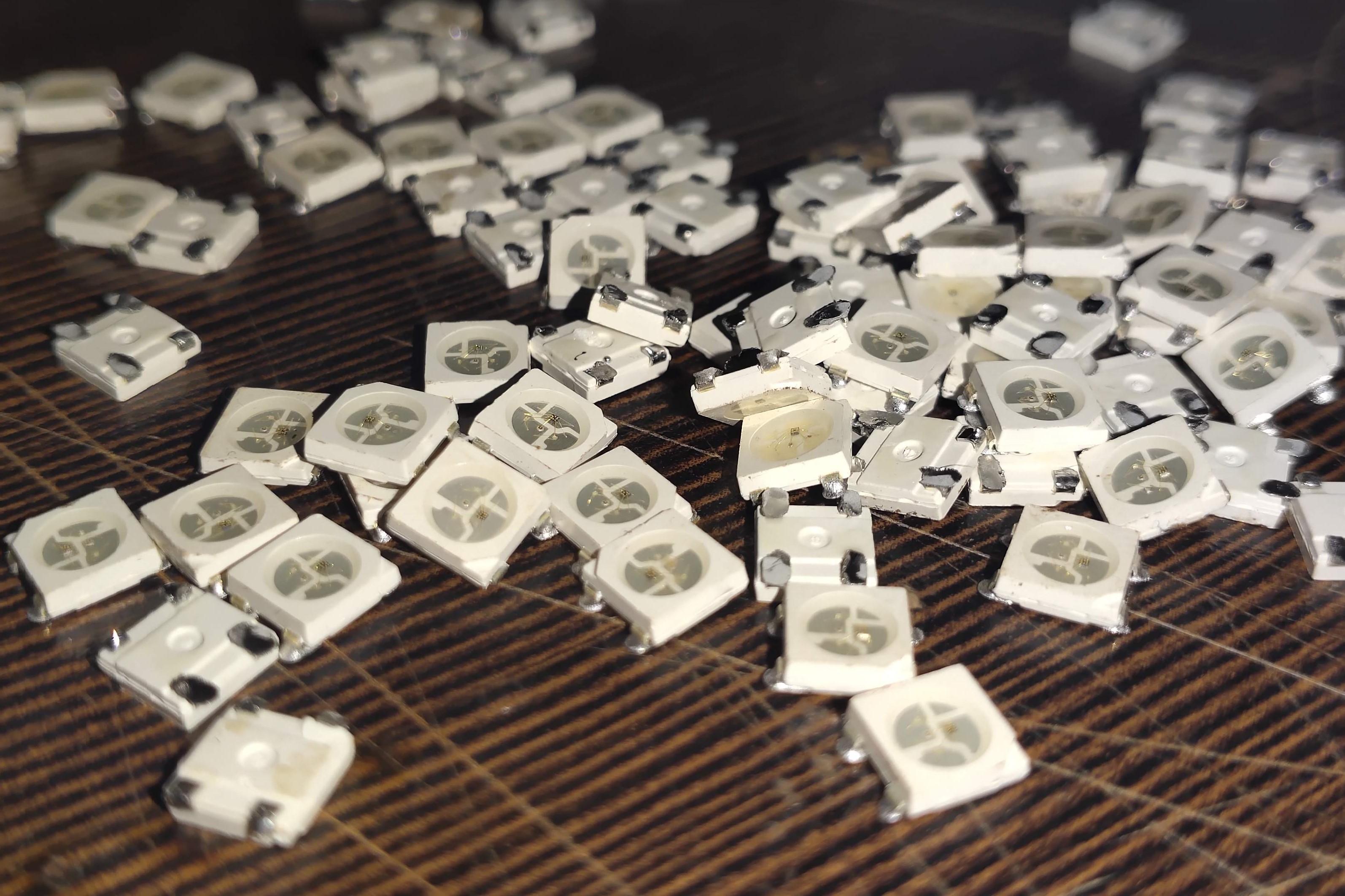
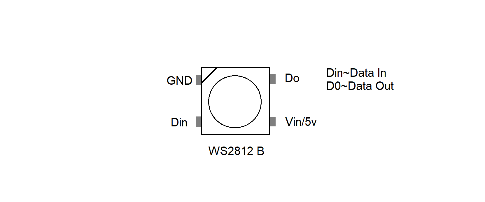
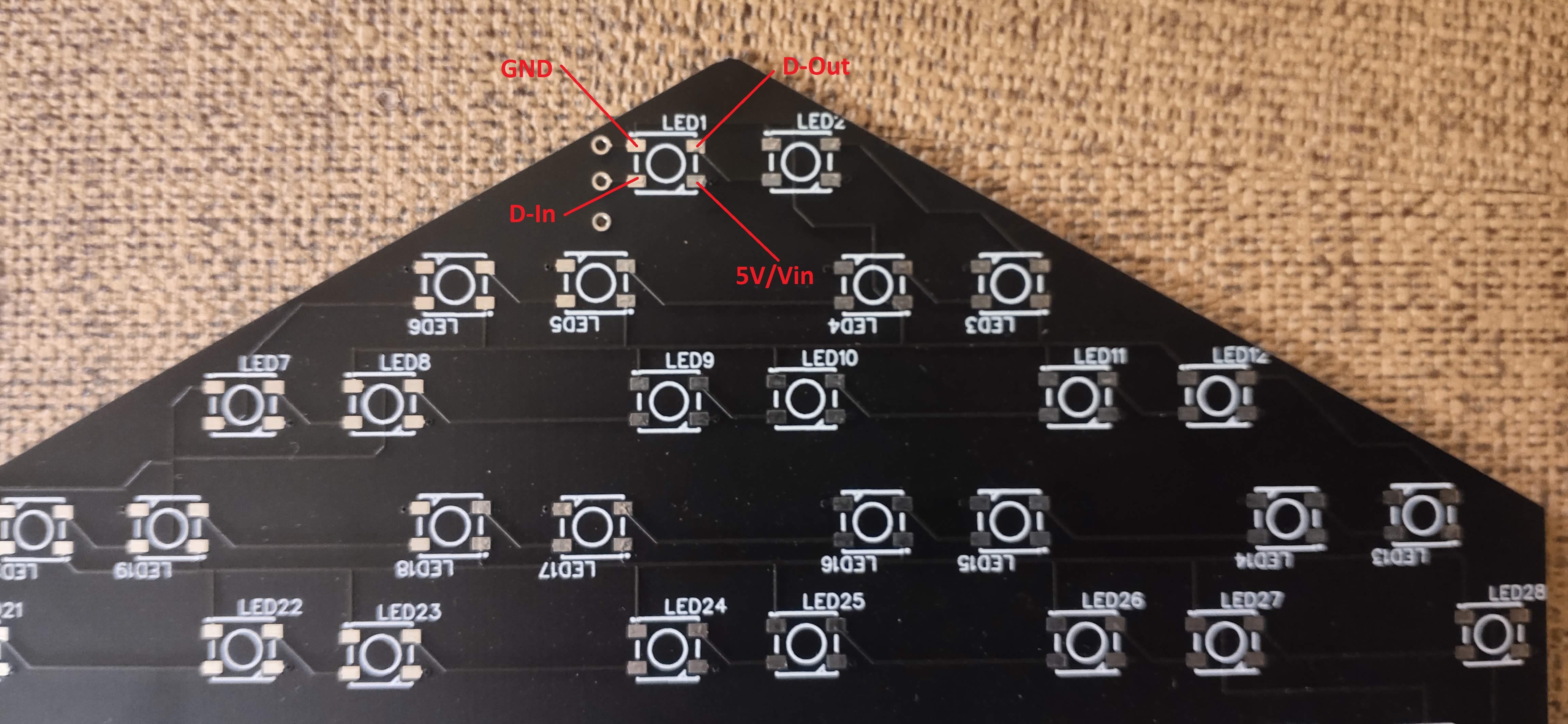

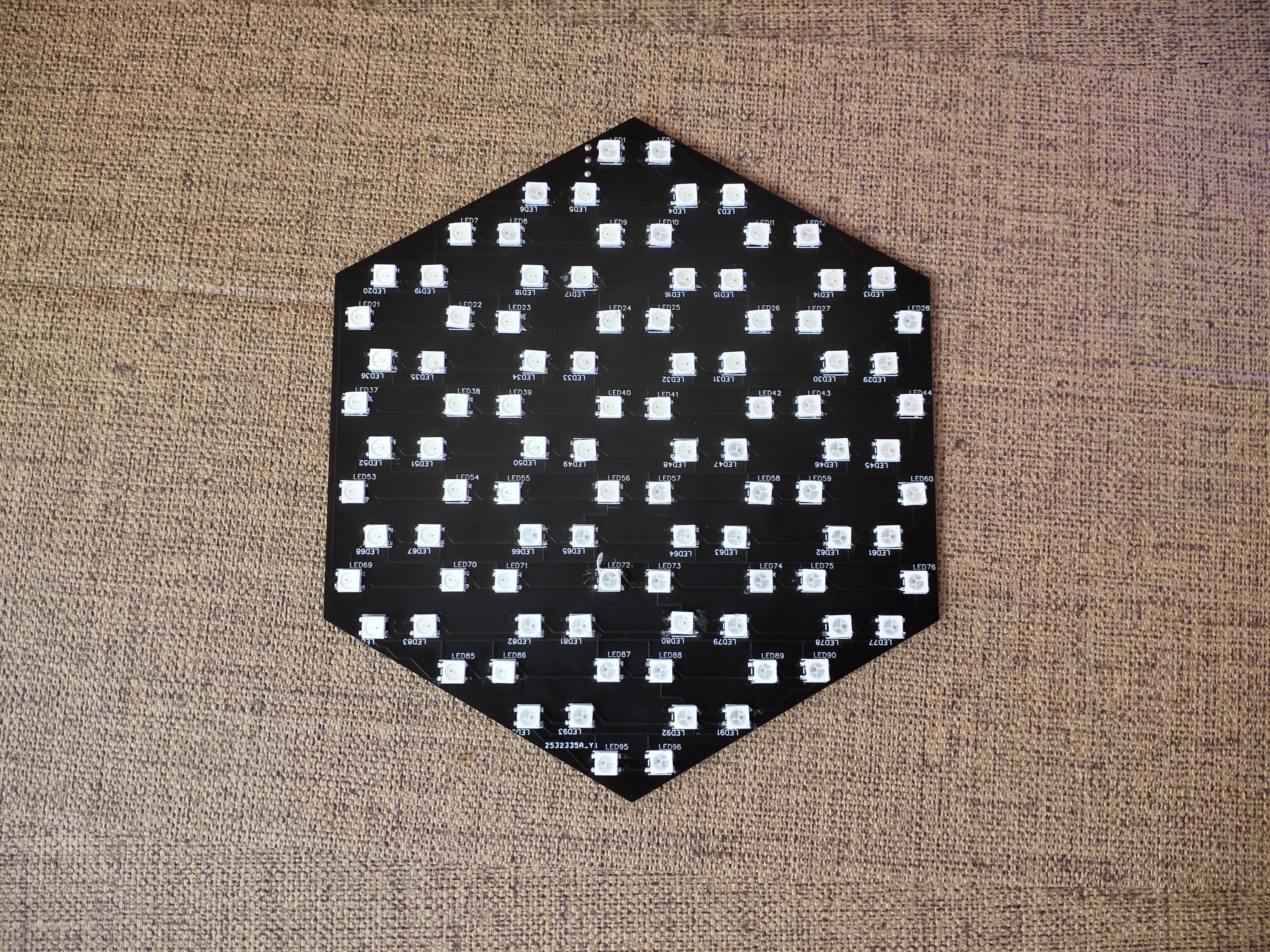
- Solder all the LEDs on PCB in correct order.
- Make all the connections as shown in circuit diagram.
- GND~GND
- Vin~5V
- D2~Din
Code:
.png)
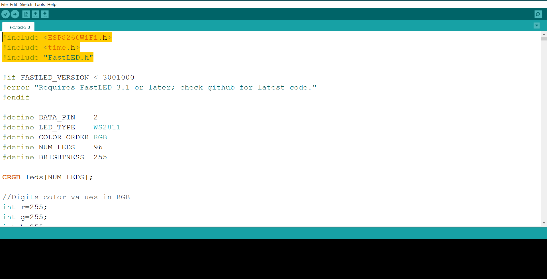
- Open the code given in Arduino IDE. Click for Code
- Install the FastLED Library and board library for ESP8266 boards.
- Type your Wifi_Name and Password
//Your Wifi info
const char* ssid = "Wifi_Name";
const char* password = "Password";
- Enter the time zone of your country
//Your time zone
int timezone = 5.5 * 3600;
- If say for me in India time zone is 5:30 I have typed 5.5,similarly you have to put time zone of your country.
- Select the Board type as ESP8266 (NodeMCU),select the port and upload the code.
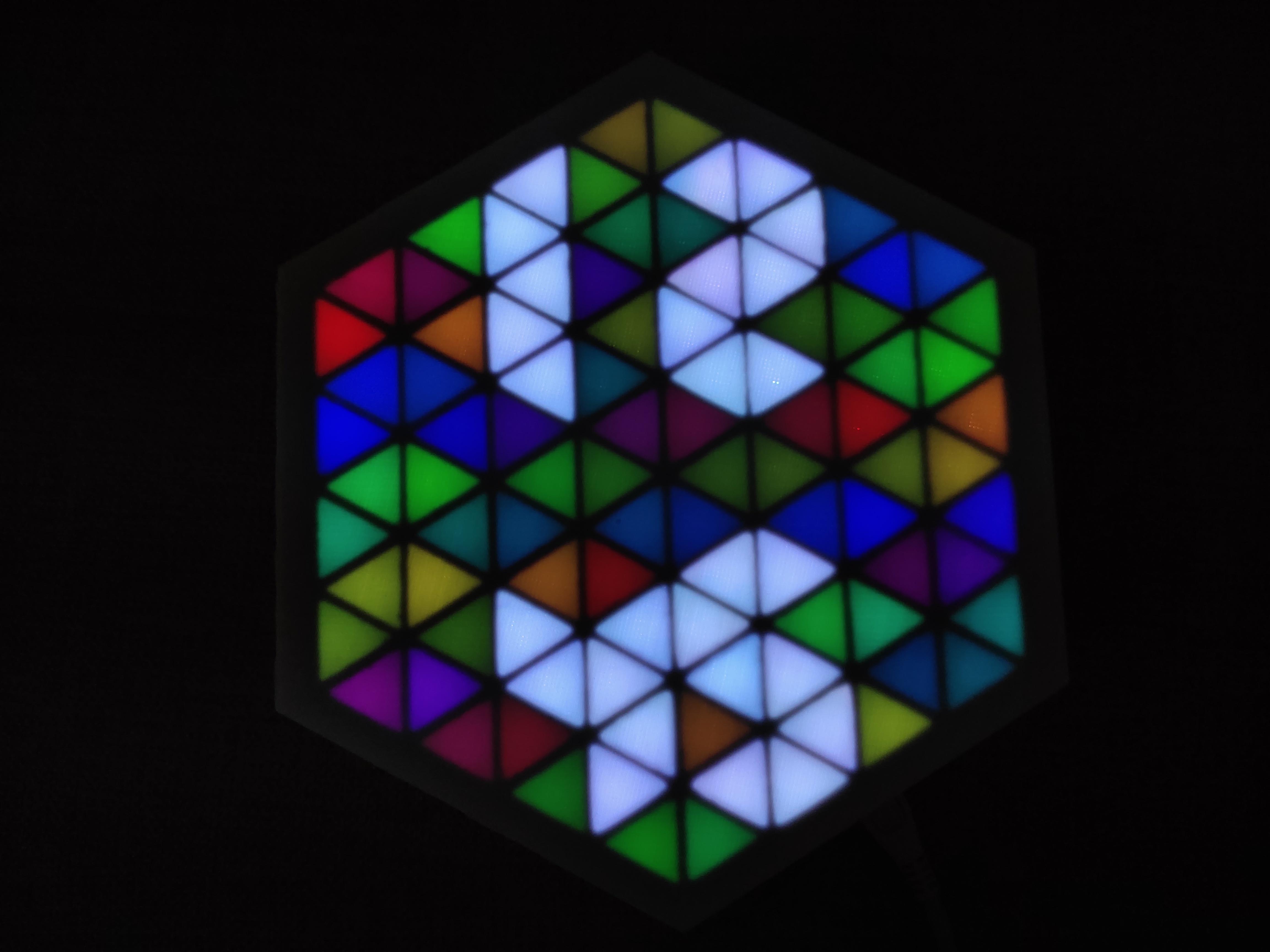
- After the code is successfully uploaded check the Matrix by powering it with micro USB adapter.
- You can even display animations from FastLED library examples.
Final:
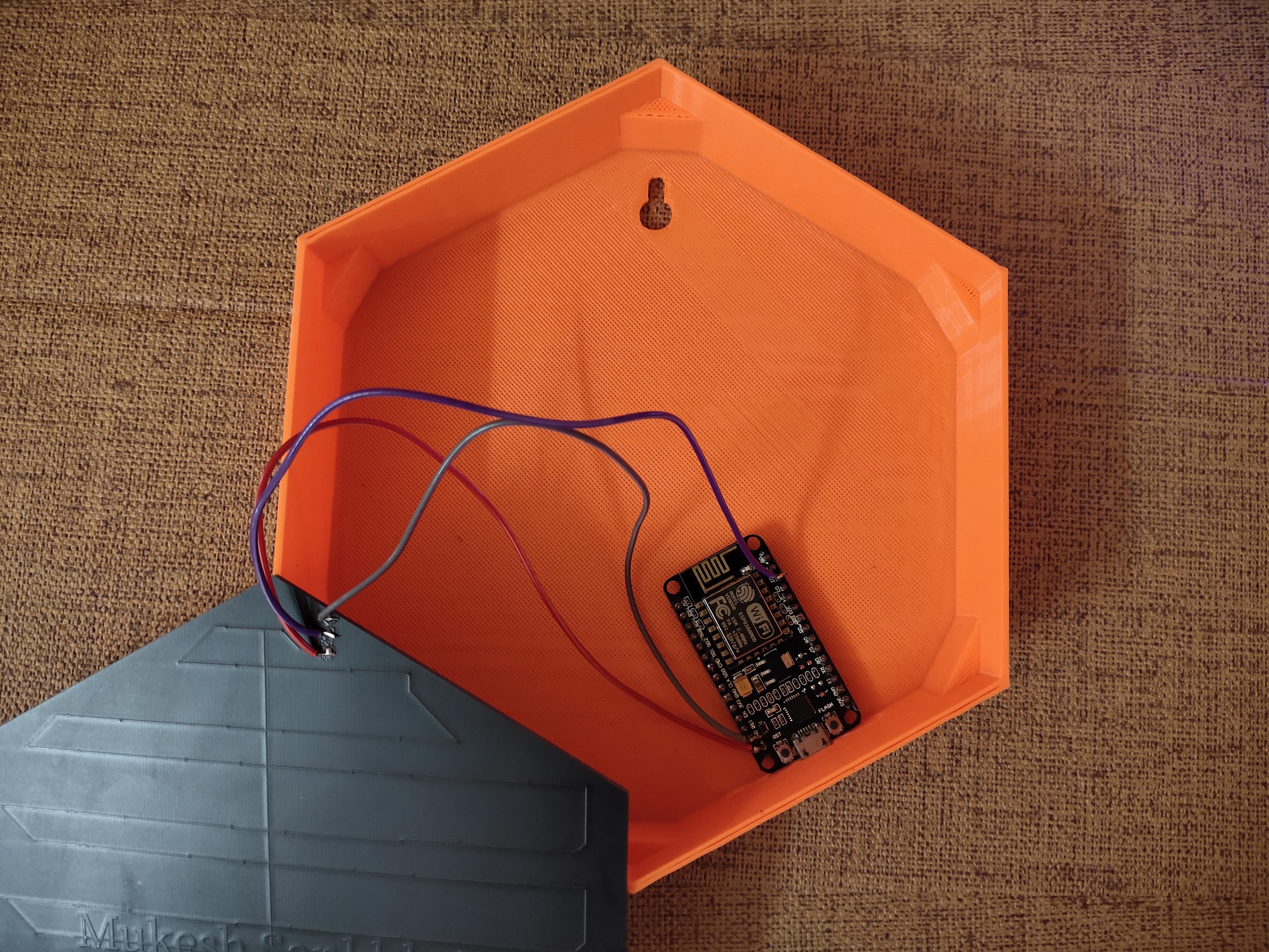
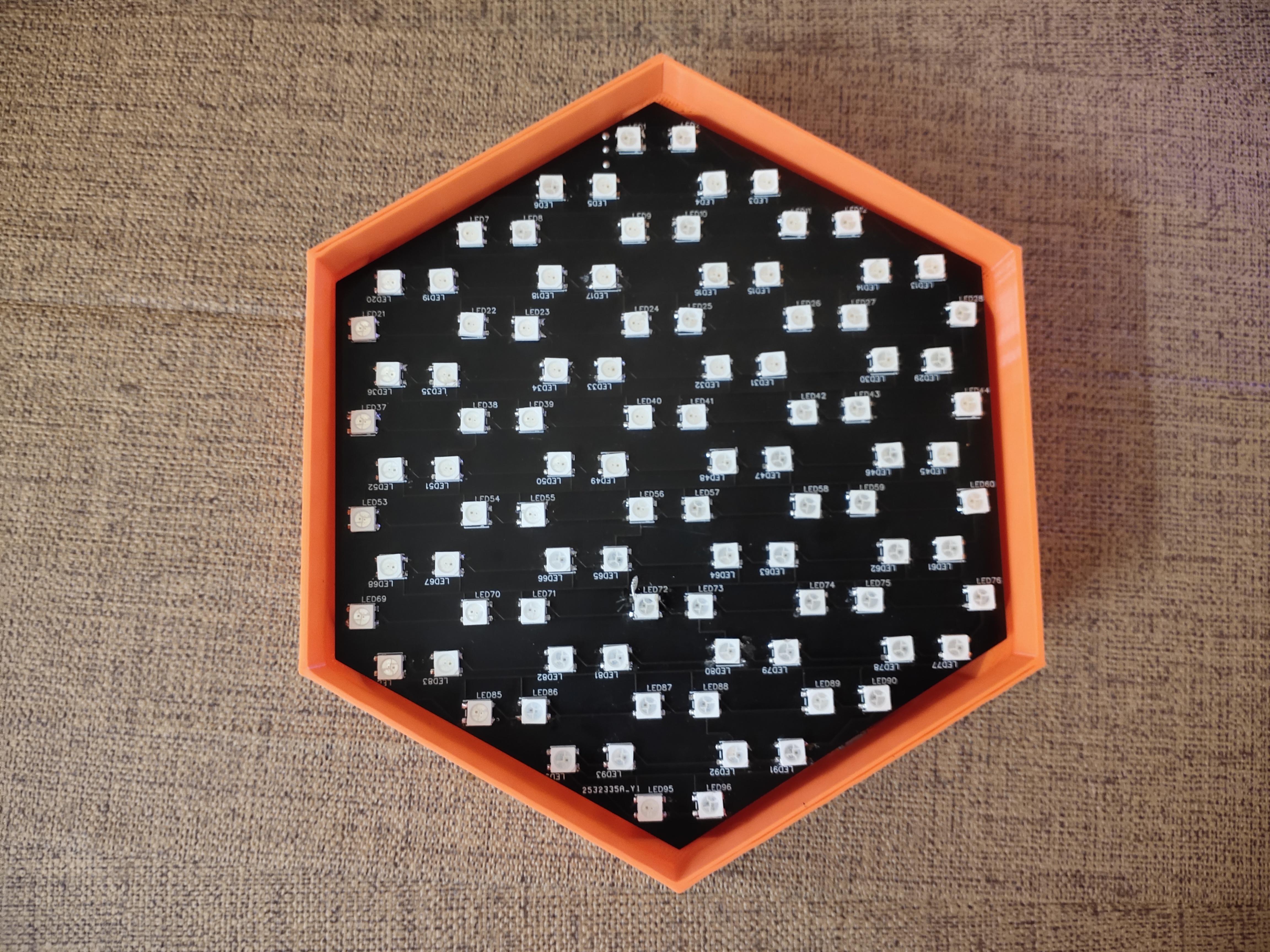
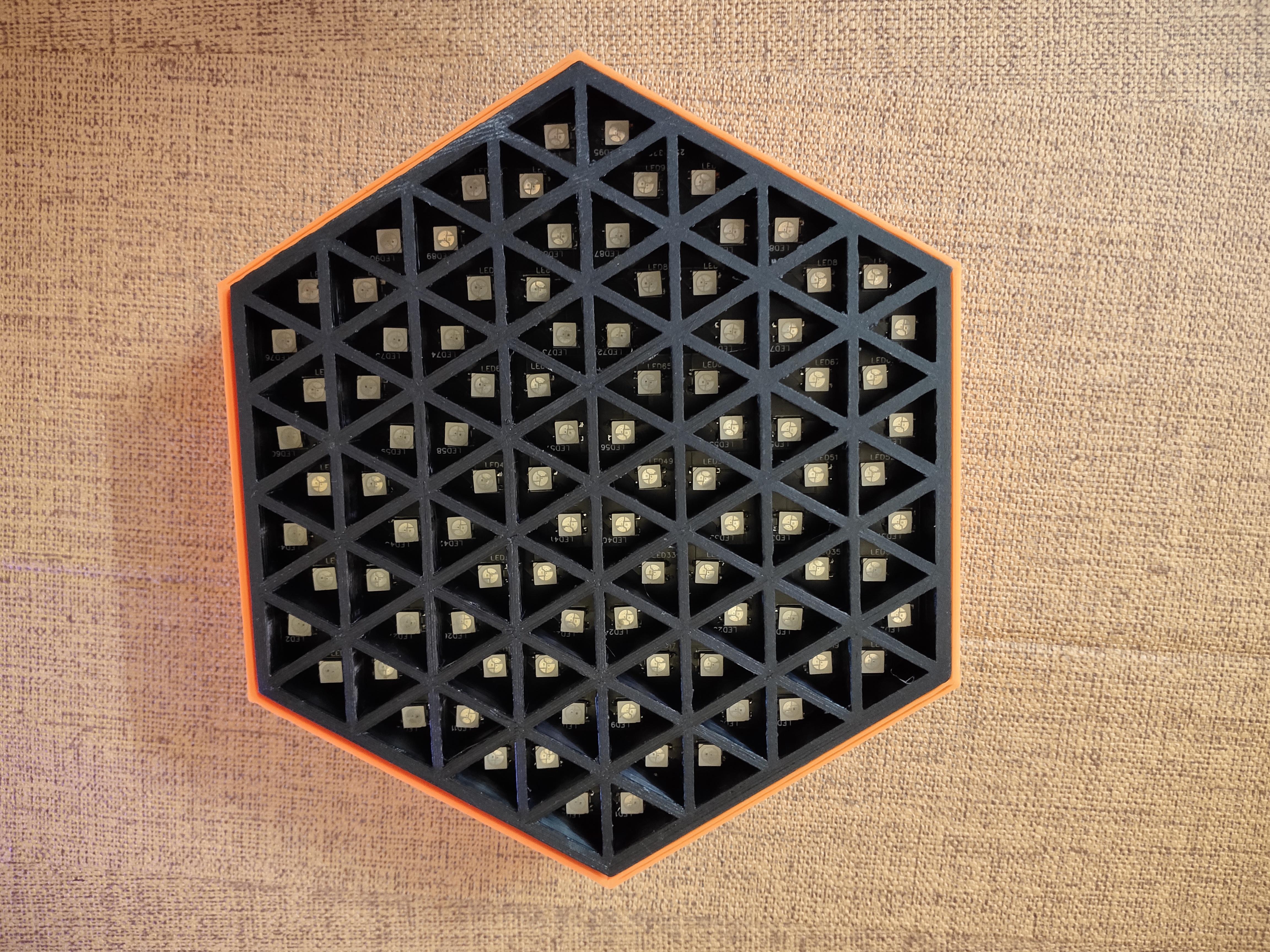
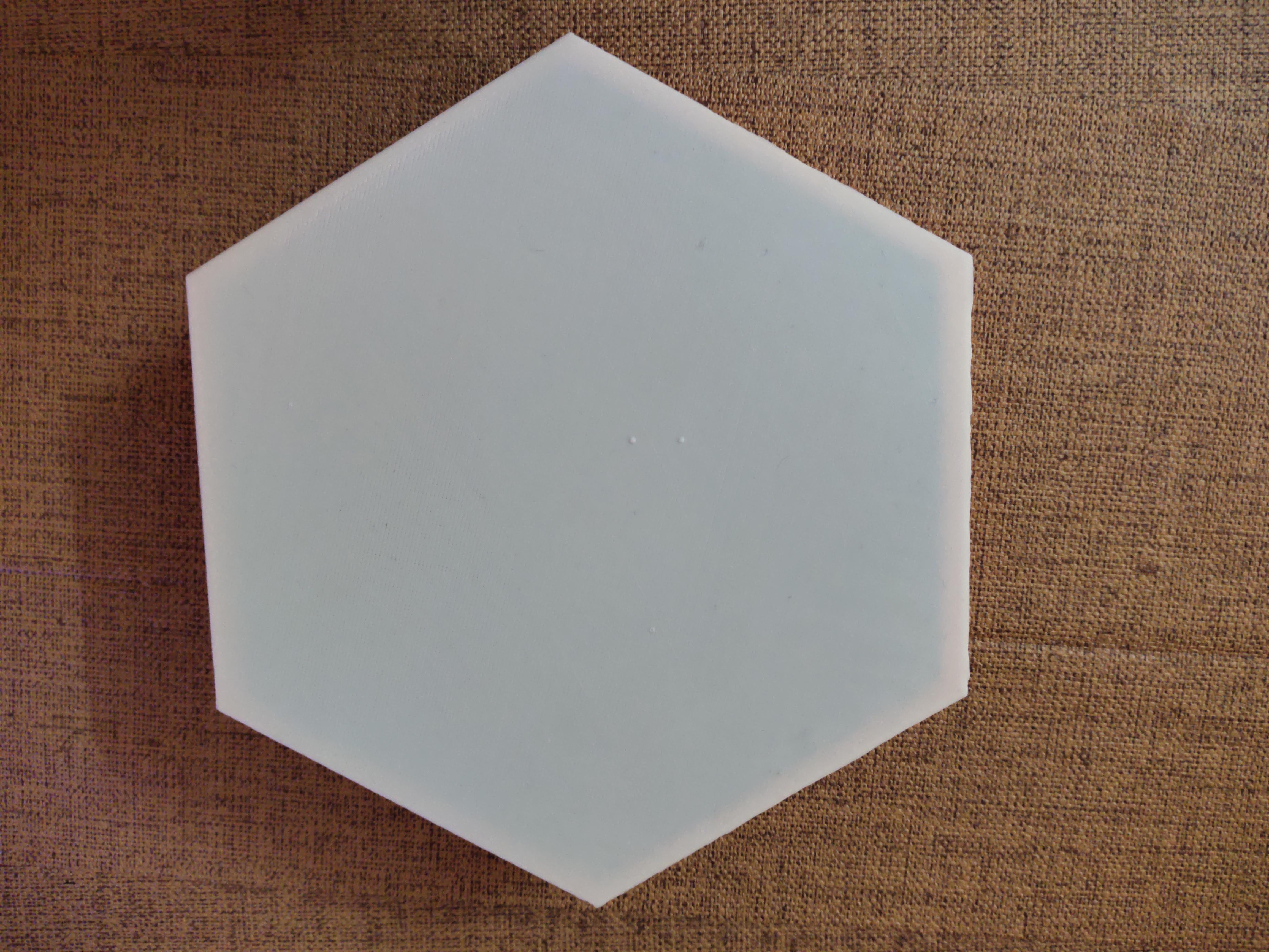
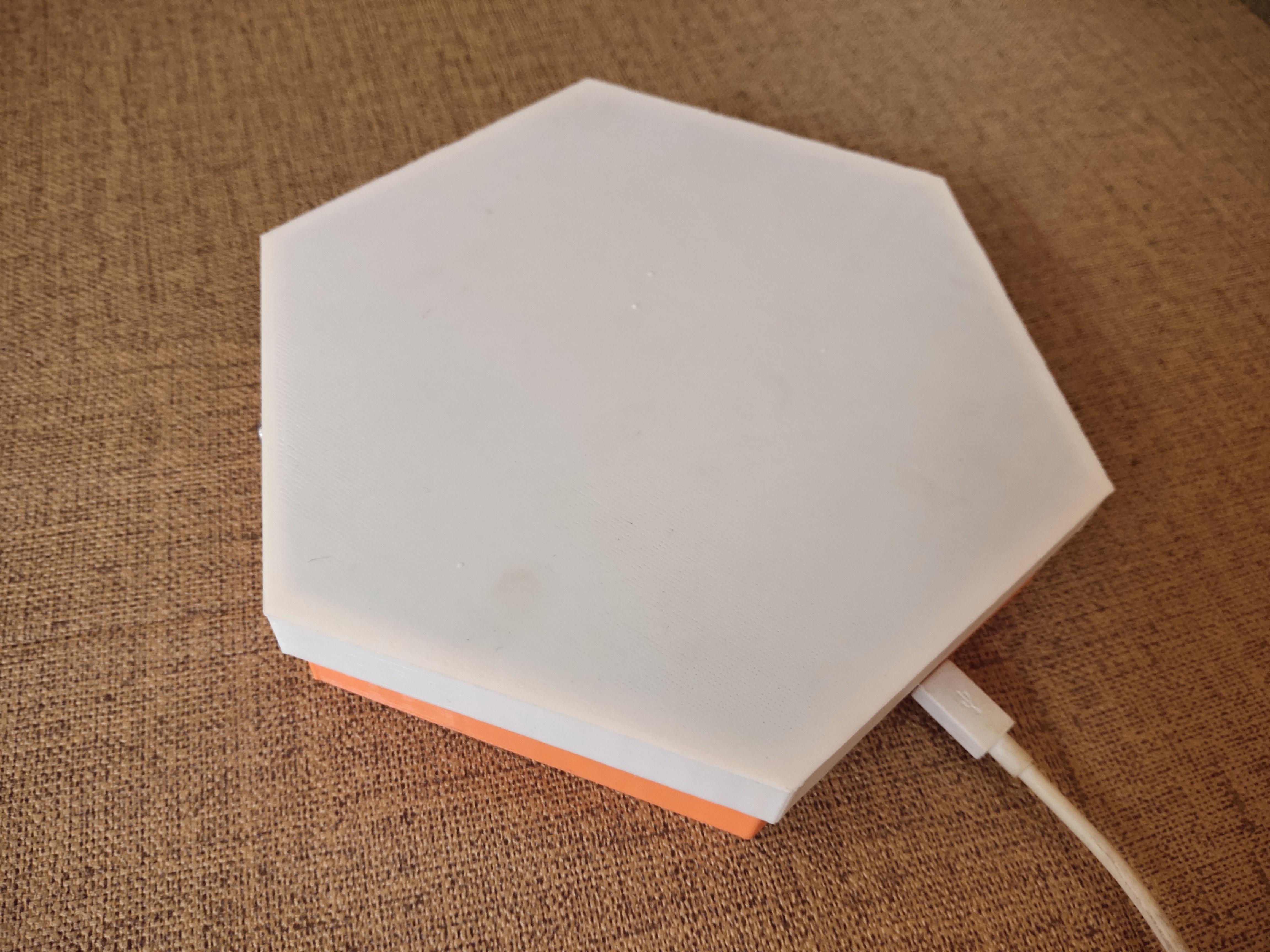
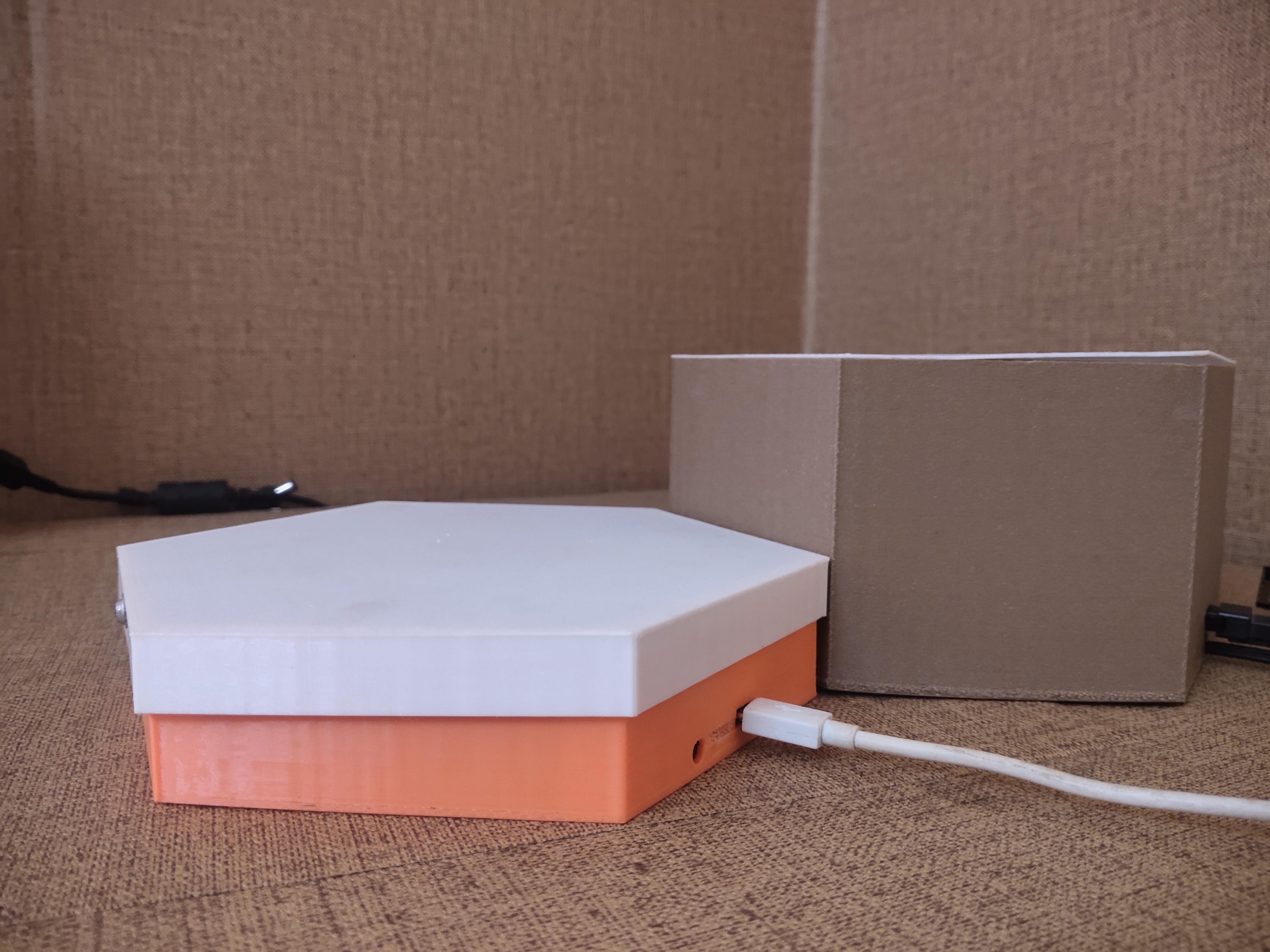
- Cut the legs of the NodeMCU board and put everything in the enclosure.
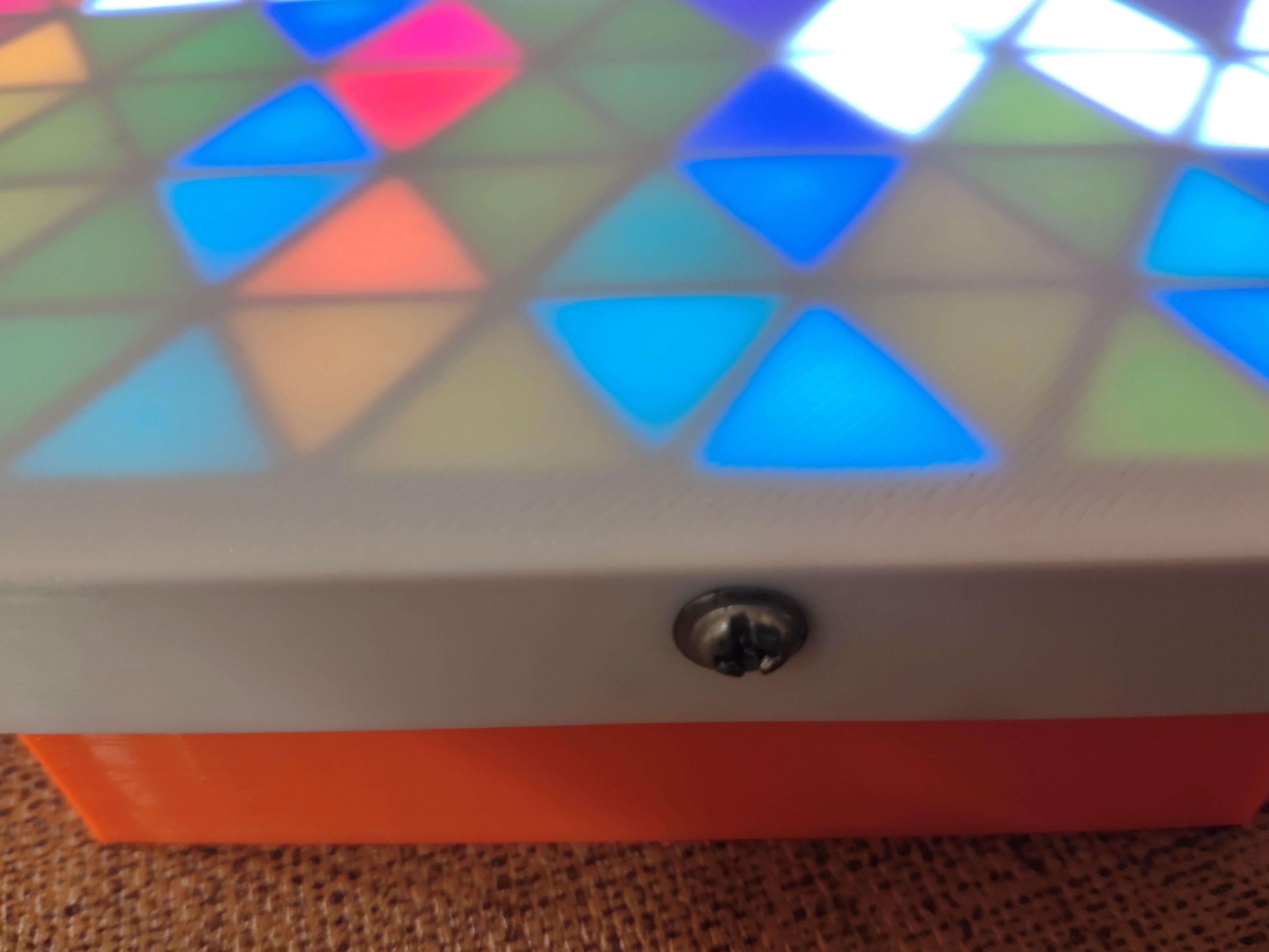
- Put the screen and make some holes with drill and screw the sides.