RGB Colour Catching Game
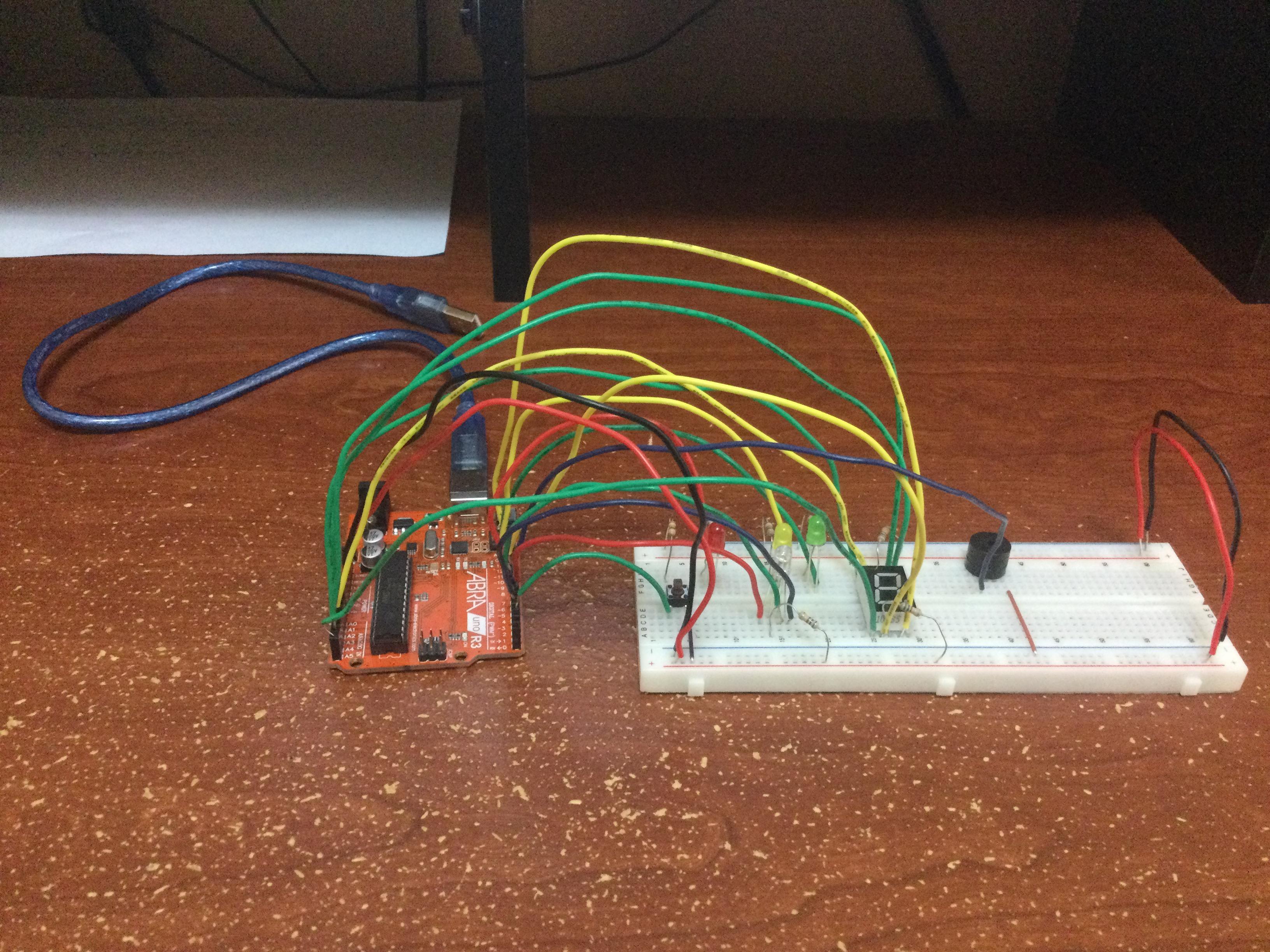
This Instructable will explain how to make an RGB colour catching system powered by an Arduino. Each component used in making this system will be listed below, and the process of making the system will be shown as a detailed step-by-step consisting of the hardware to even the code of the system.
Step 1: Supplies
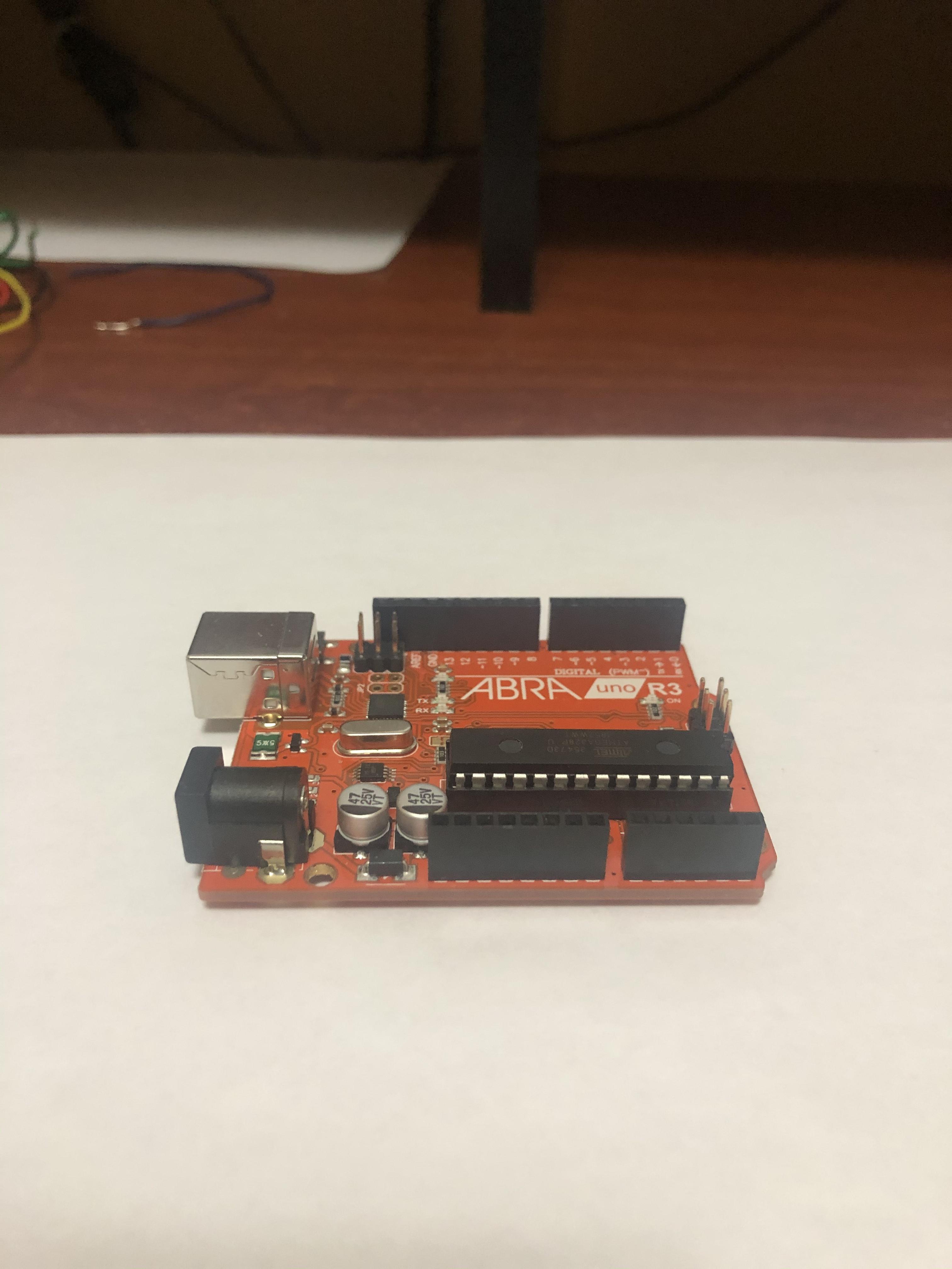
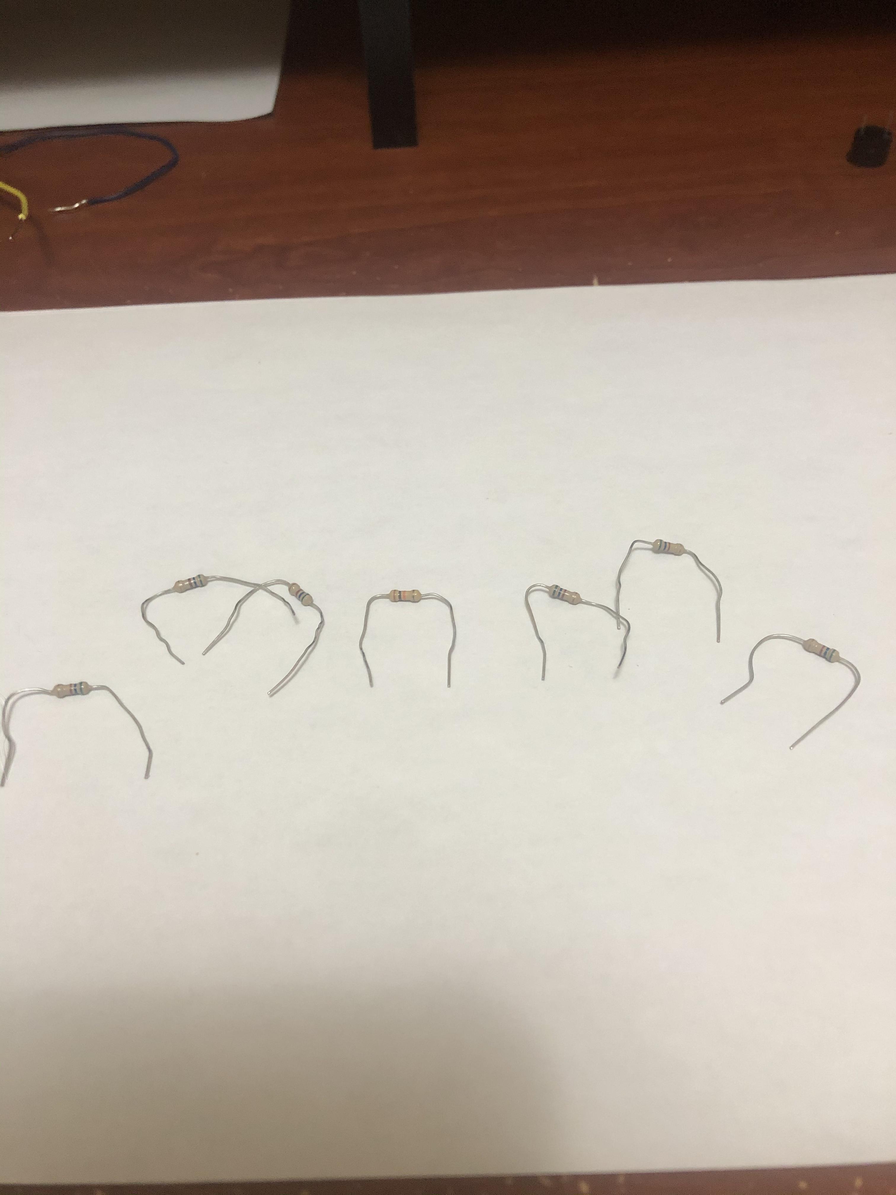
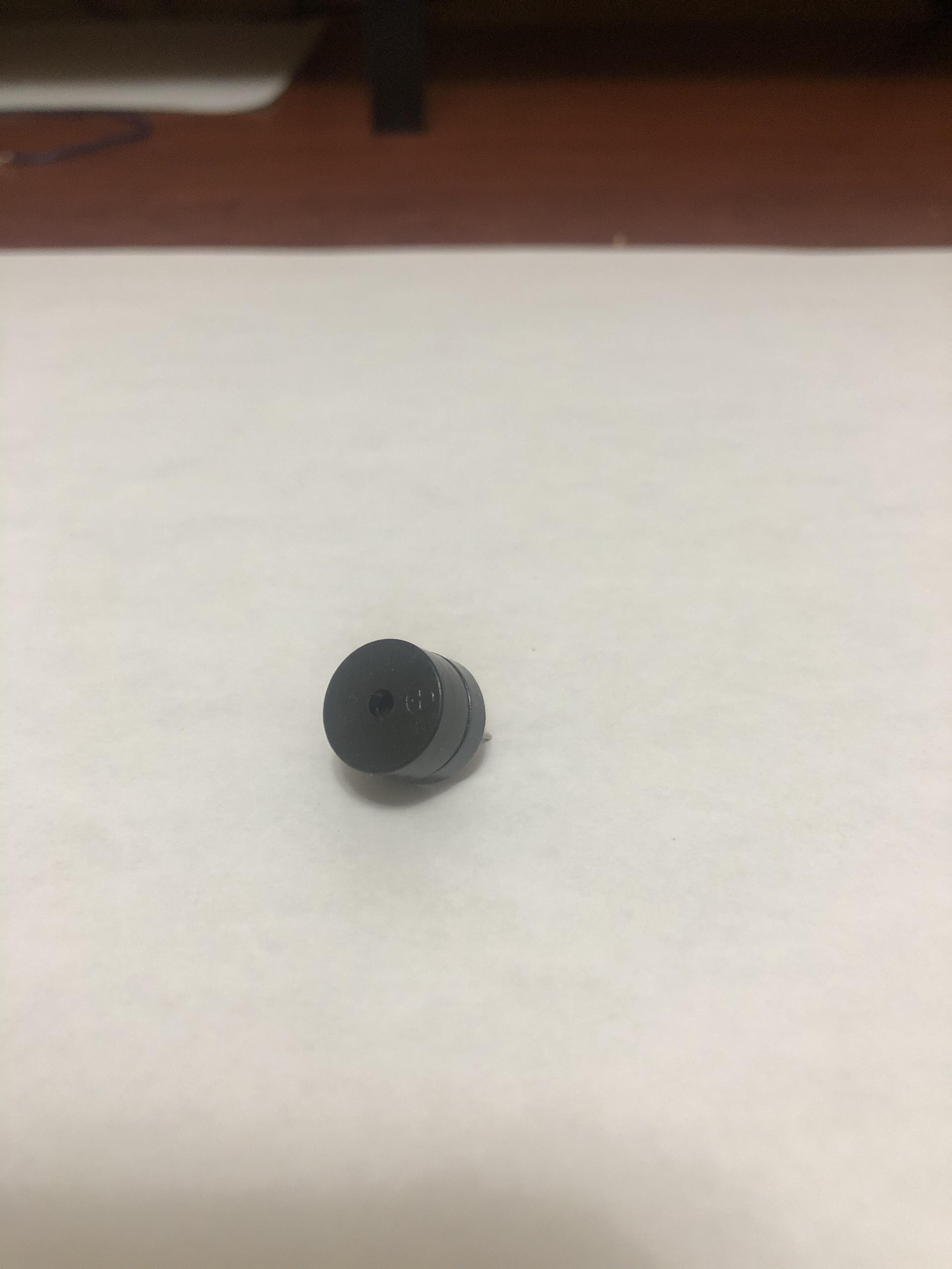
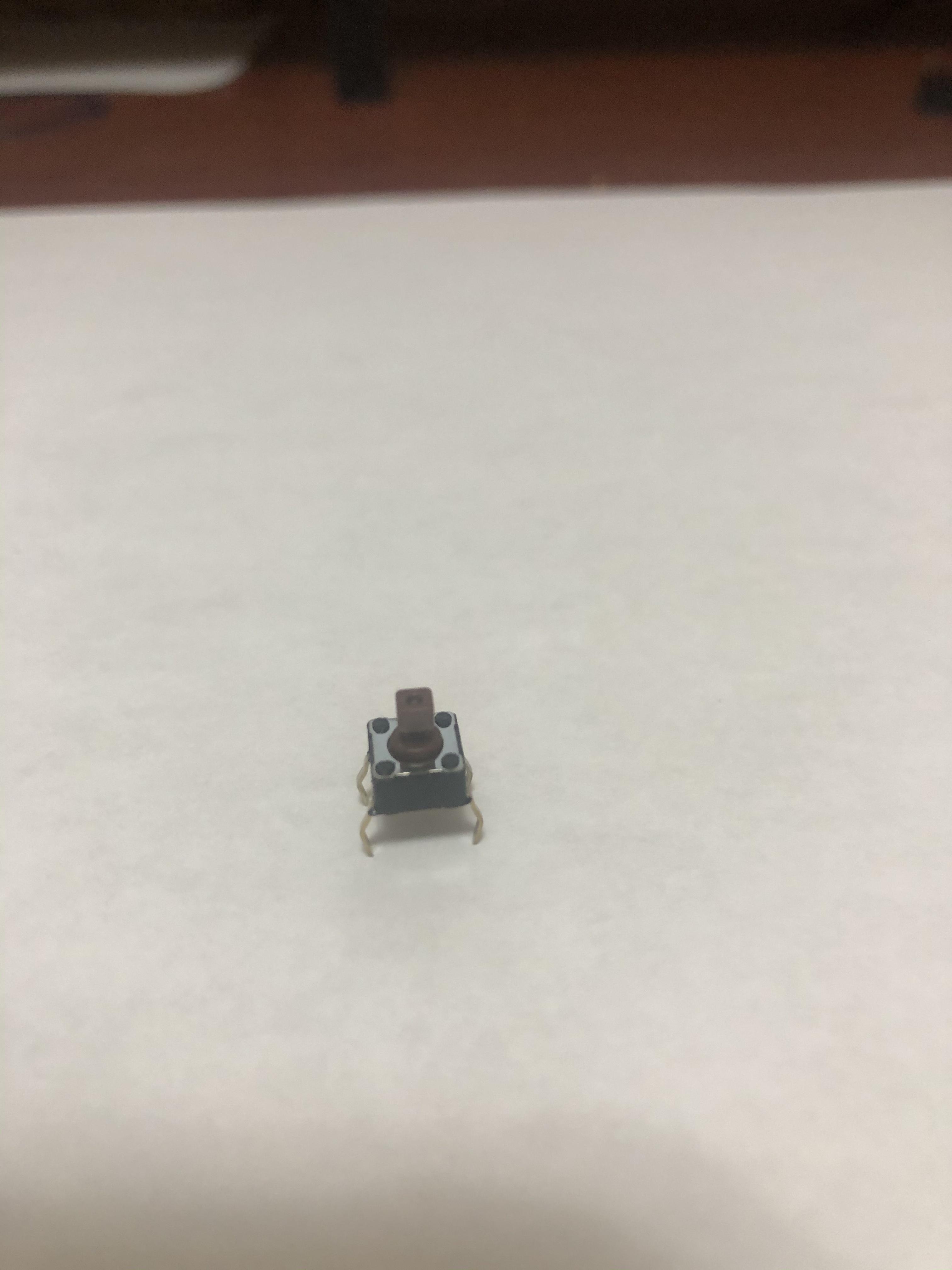
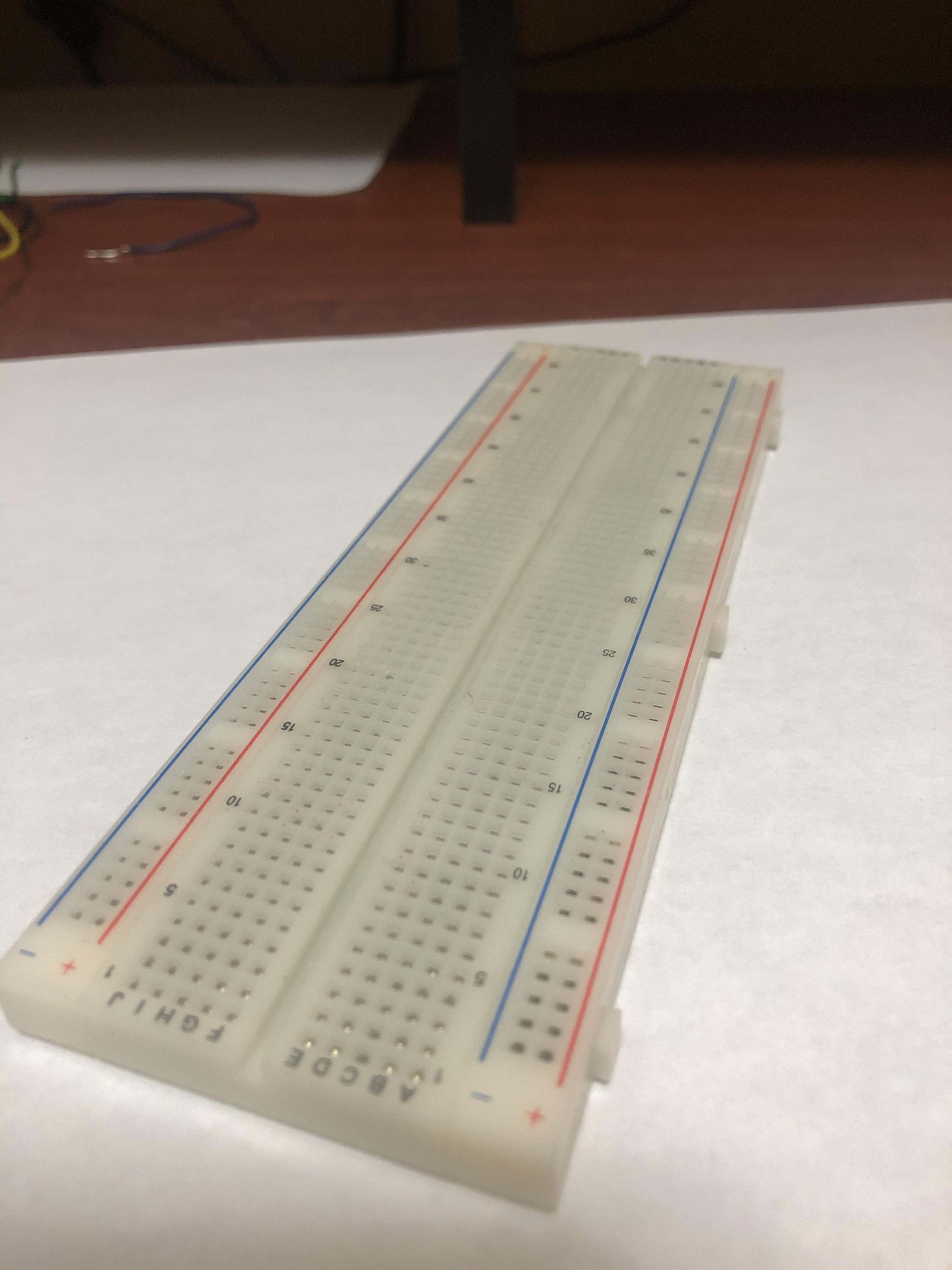
Arduino Uno
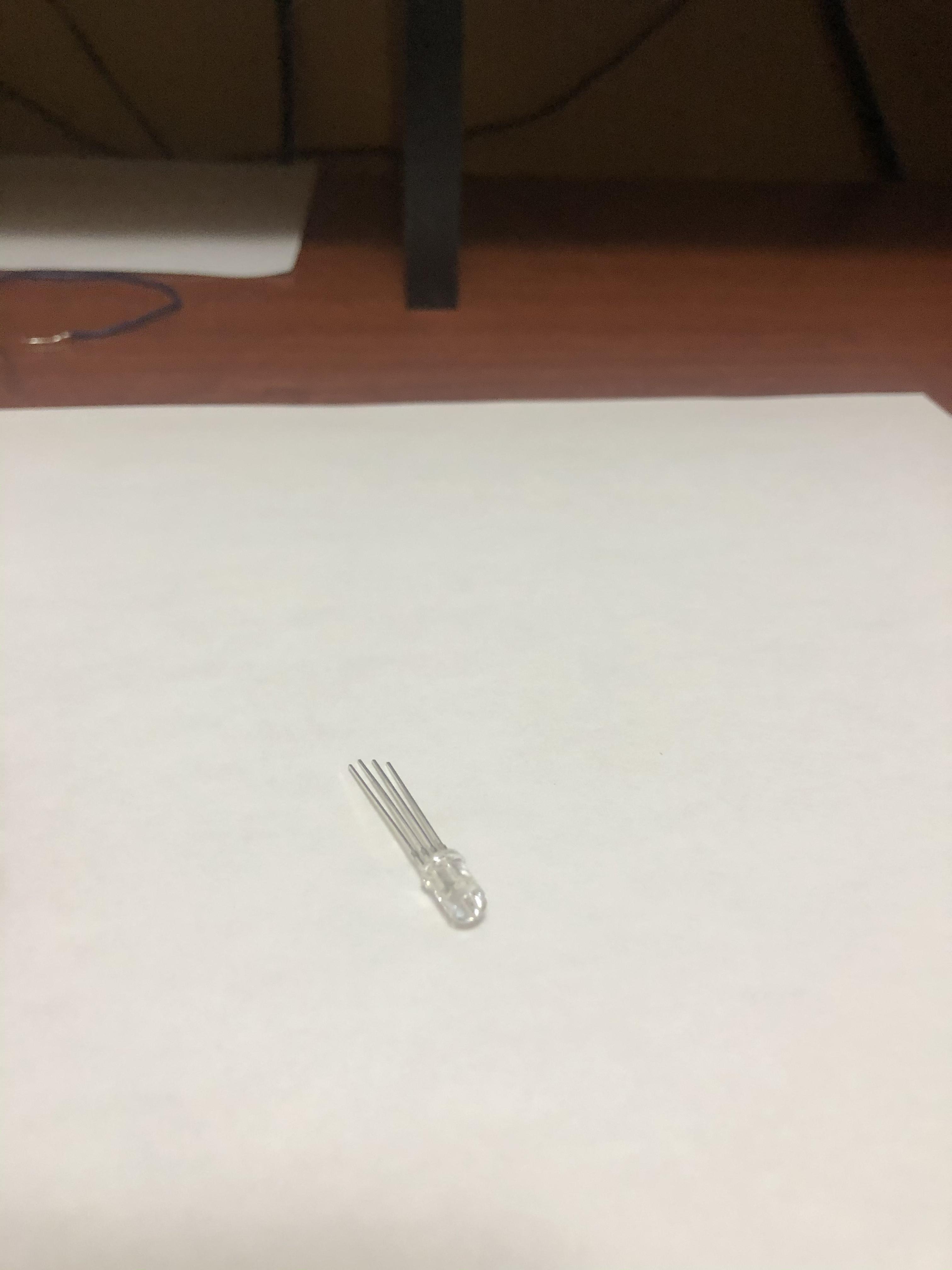
RGB Led
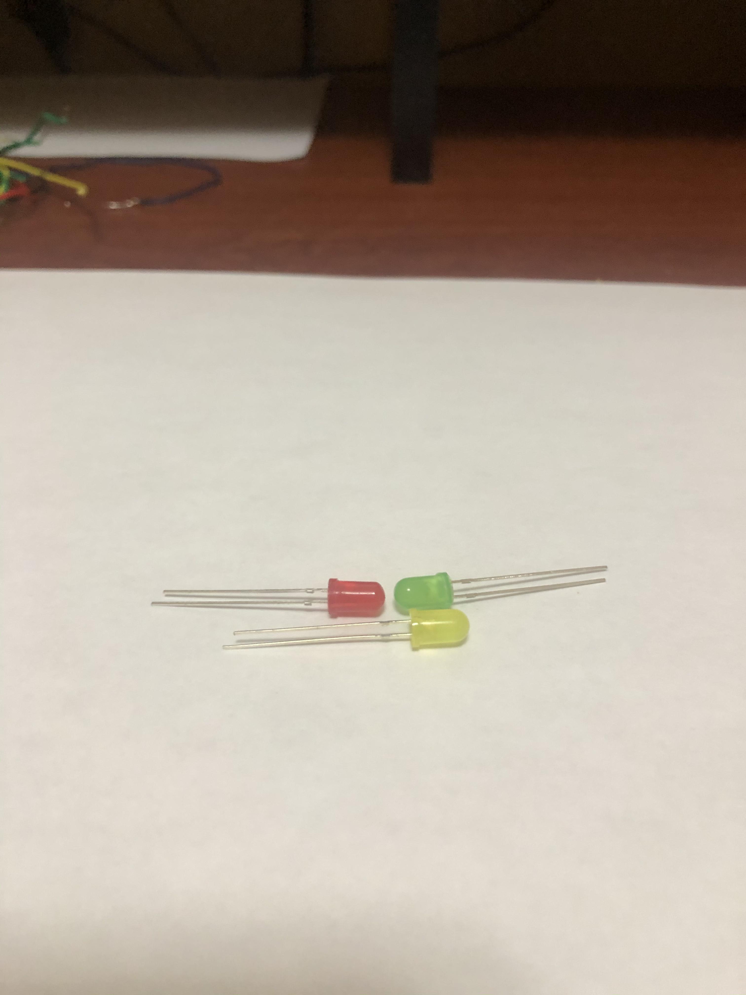
Three LEDs (Red, Green, Yellow)
Seven Resistors (Six 560 Ohm, One 1000 Ohm)
One Buzzer
One Push Button
One Bread Board
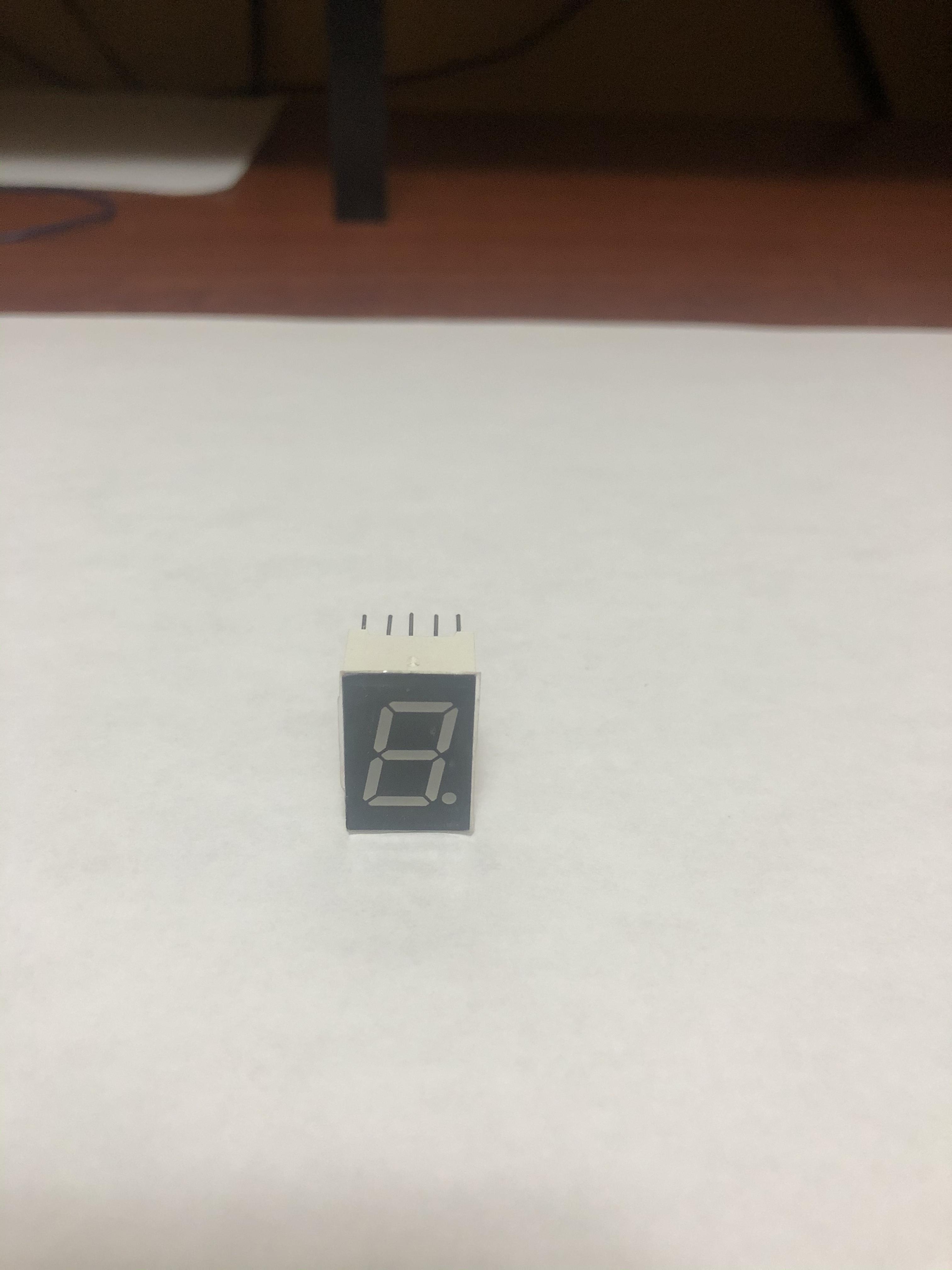
One Seven Segment Display
A ton of wires
Step 2: Wiring the Arduino
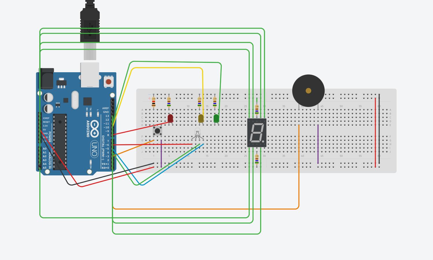
This is the rough draft of making the RGB Led Color Catching game. When looking at this system, you can see how many wires are used. This was all connected to the Arduino and when wiring the seven segment display you will see that the seven segment display is wired to analog ports rather than the typical numbered ports, due to not having enough space on all of the numbered ports.
Step 3: Wiring the RGB LED
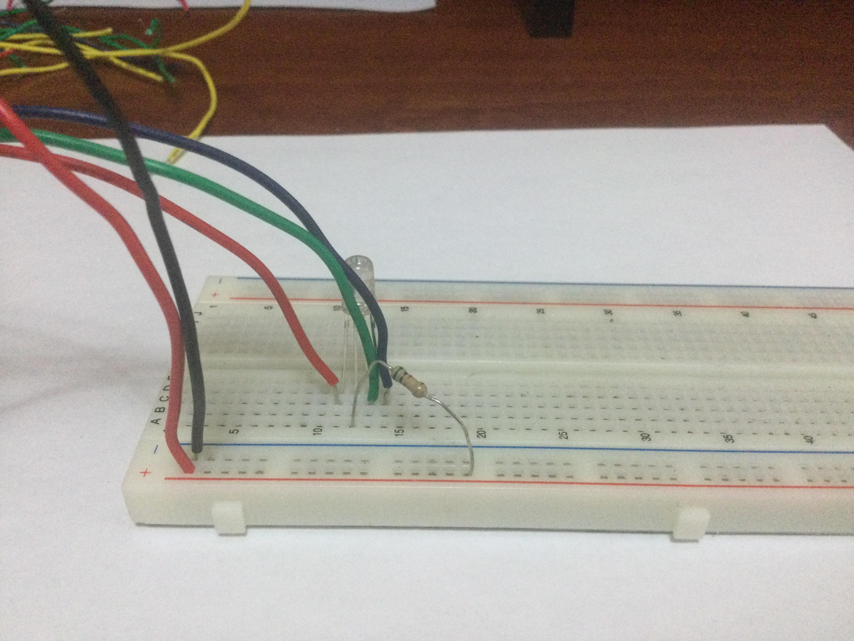
When wiring the RGB Led, you want to connect the the red to the #6 port, the green to the #4 port, and the blue to the #5 port. After doing this you would want to connect the cathode prong to the 560 Ohm resistor and connect that resistor to the 5V that is seen in the picture. This will get your RGB wired up and ready for the code input. The RGB will be changing colors to show you which color to catch.
Step 4: Three LEDs (red, Green, Yellow)
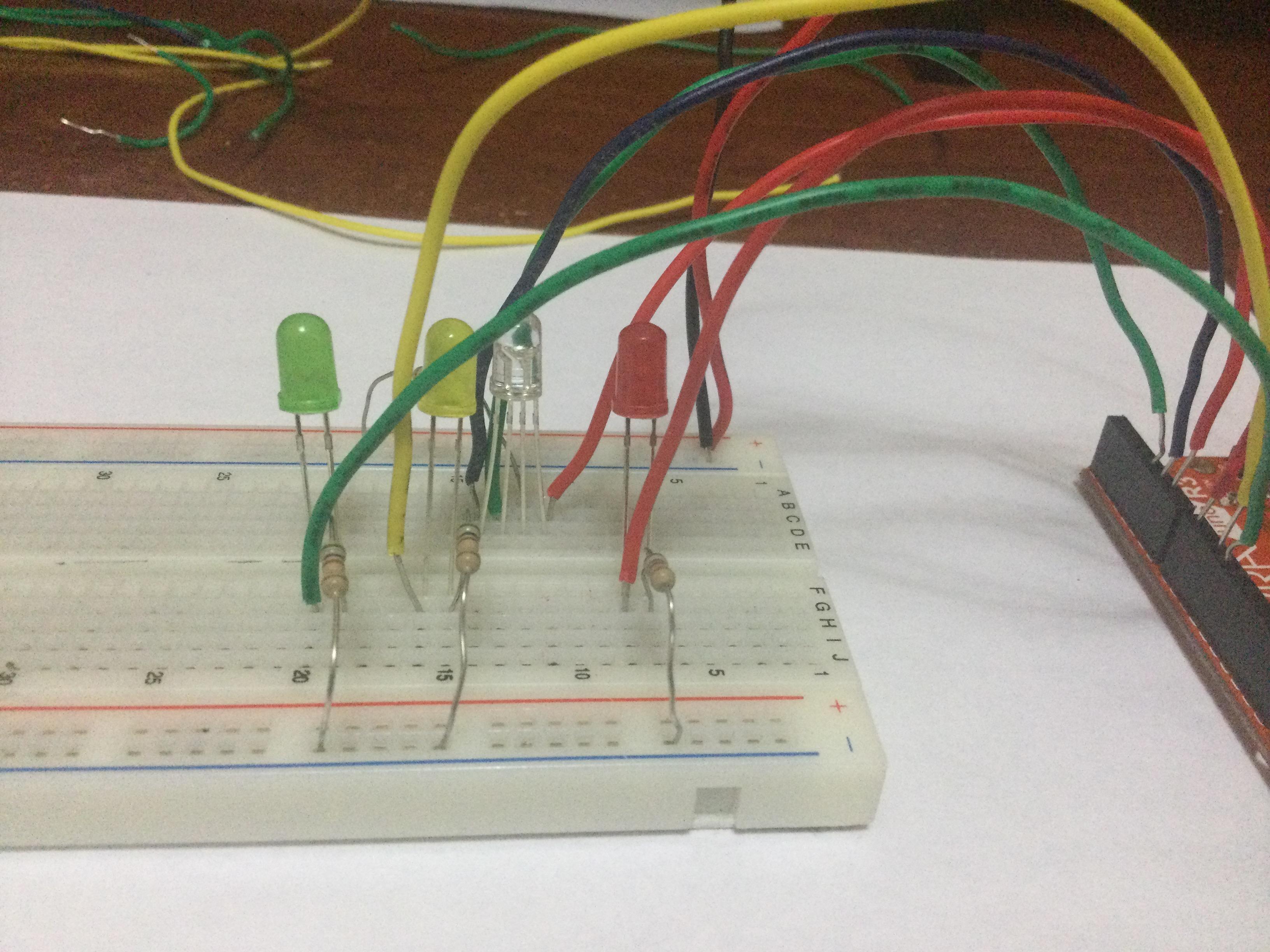
For the LEDs, you are allowed to choose any color LEDs you would like, but that would mean you would have to change the code to fit whatever color LED you would like to use. When wiring the LEDs, You want to wire the red LED to the #8 port, the yellow LED to the #10 port, and the green LED to the #11 port. After doing so, you would want to wire 3 560 Ohm resistors to each different LED as shown in the photo. The LEDs will be switching on and off between each other, giving you an interval of time to catch one of the three colors.
Step 5: Wiring the Buzzer
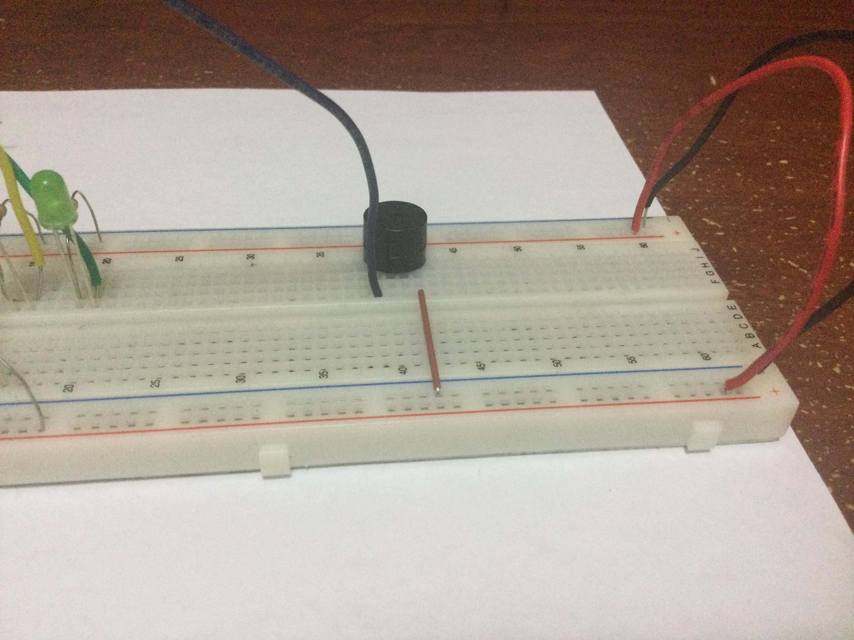
The Buzzer is quite simple to wire. All it takes is a wire coming from port #7 to the positive prong of the buzzer, and a wire coming from ground, which sends power from negative to the negative prong on the buzzer. Once this is done your buzzer is already ready to work. The Buzzer will buzz if you catch the wrong color in the game.
Step 6: Push Button
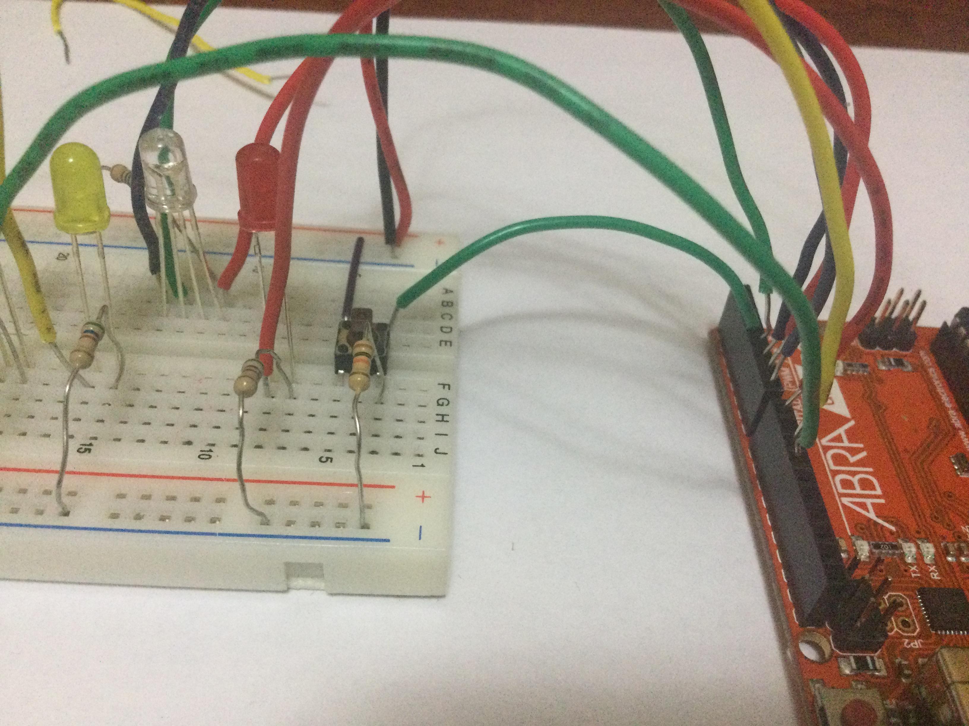
In wiring the push button, you want to make sure your push button is wired and has terminal 1a connected to port #3. After this, you want to use a wire that is connected from the 5V positive to terminal 2a. Finally, you would want to have a 1k Ohm resistor connected to terminal 1b from the negative at top of the bread board. This will have your push button working. The push button looks simple but can sometimes be a little tedious to wire correctly, so be careful. the push button will be pressed once the LED is changed to the corresponding color of the RGB LED.
Step 7: Seven Segment Display
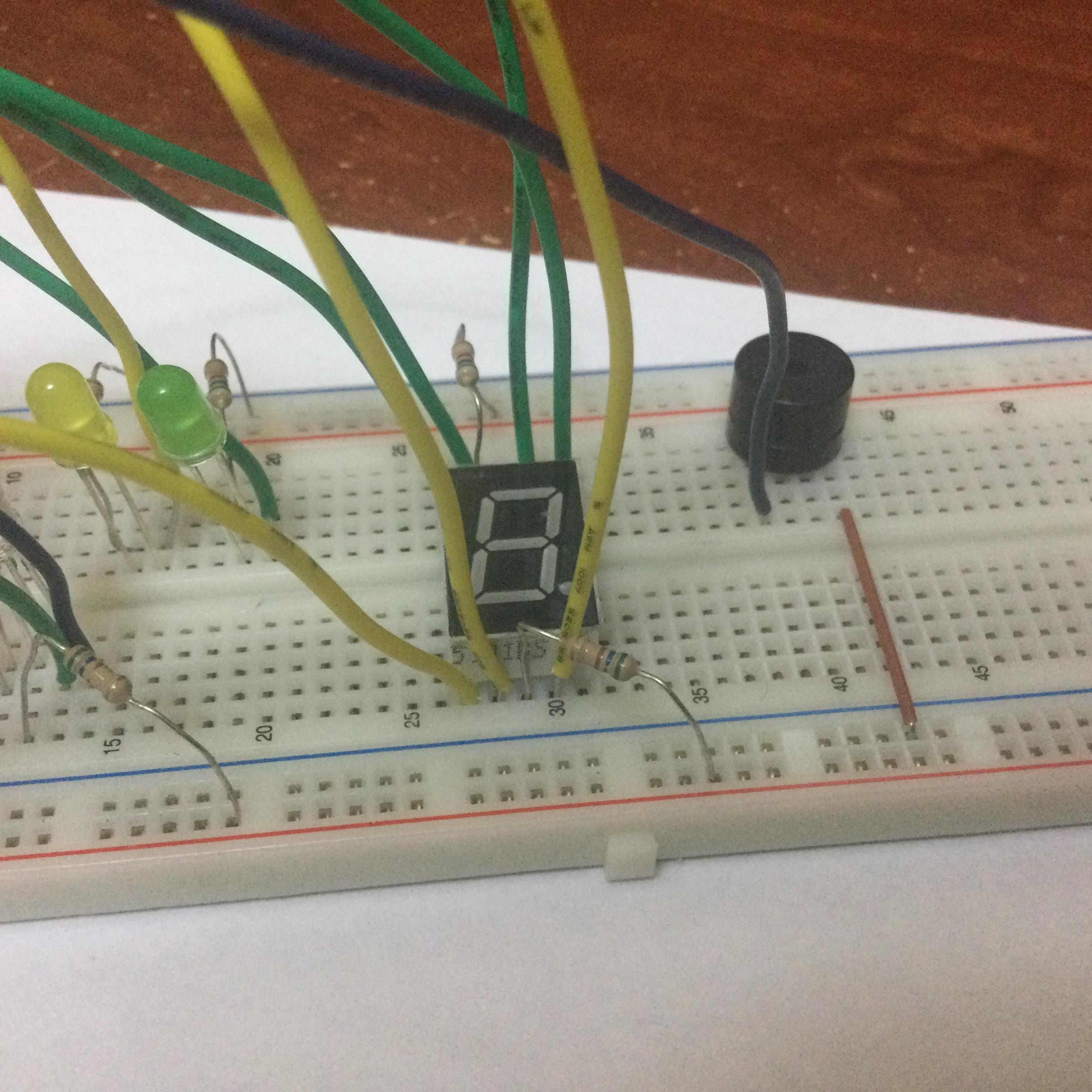
The Seven Segment Display will be the most tedious one to wire. This takes majority of the wires and ports on the Arduino. You want to have ports A0, A1, A3, A4, A4, 9, and 13 wired in that order starting from the top left of the Seven Segment Display to the right and then to the bottom left to the right. You will also need to wire 2 560 Ohm resistors connected to the two common prongs and to the 5V positive on the top and bottom of the bread board. Your Seven Segment Display should be wired similar to that which is shown in the photo. The Seven Segment Display will display your score depending on how many times you caught a color. it will show a score for catching a negative amount of colors or a positive amount of colors.
Step 8: Code
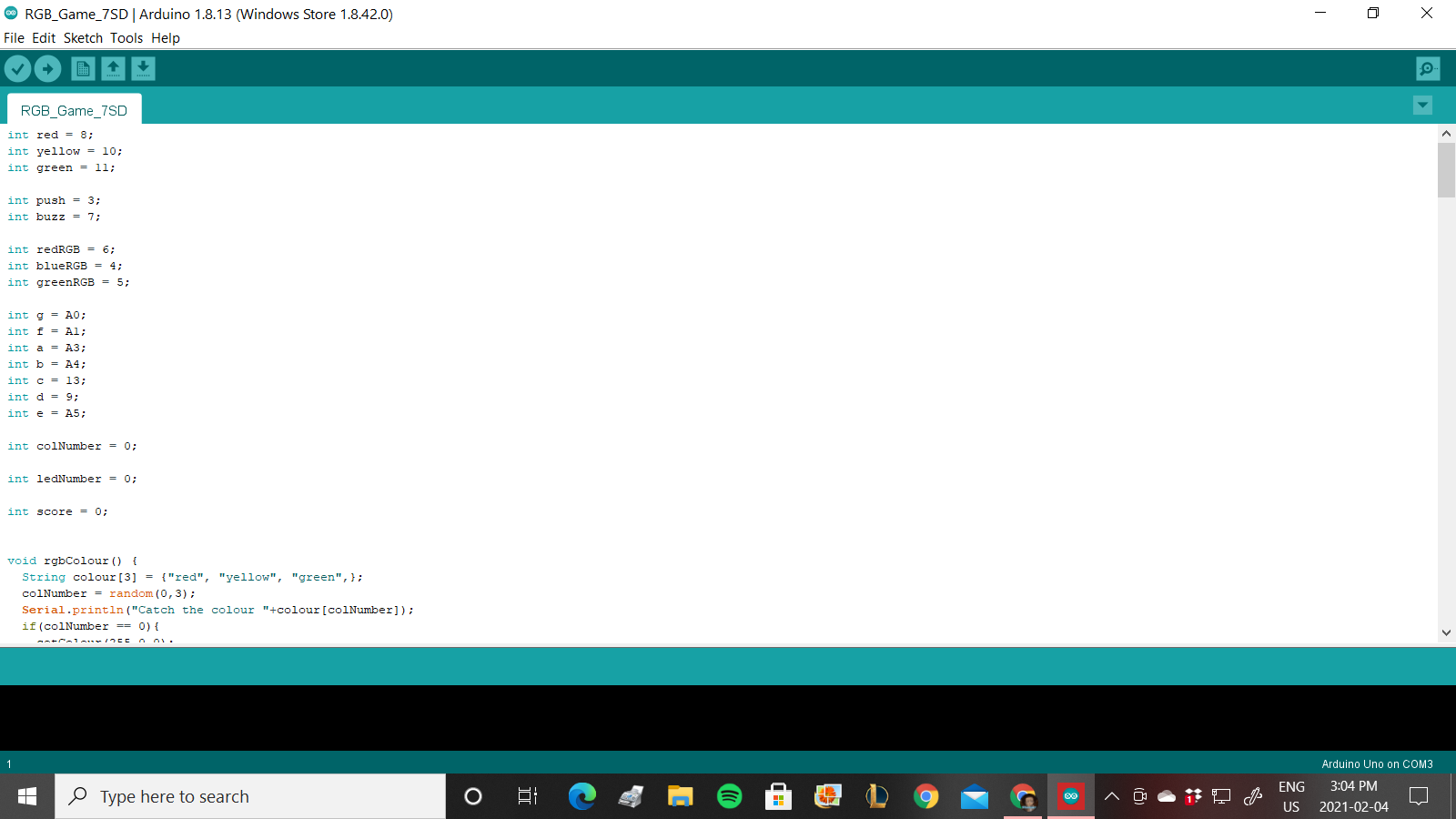
The Code is quite long but if done correctly you will finally have your working RGB LED Color Catching Game. You will need to check the serial monitor to see which color to catch more clearly if needed. The code is pasted down below.
int red = 8;
int yellow = 10; int green = 11;
int push = 3; int buzz = 7;
int redRGB = 6; int blueRGB = 4; int greenRGB = 5;
int g = A0; int f = A1; int a = A3; int b = A4; int c = 13; int d = 9; int e = A5;
int colNumber = 0;
int ledNumber = 0;
int score = 0;
void rgbColour() { String colour[3] = {"red", "yellow", "green",}; colNumber = random(0,3); Serial.println("Catch the colour "+colour[colNumber]); if(colNumber == 0){ setColour(255,0,0); } else if ( colNumber == 1){ setColour(255,255,0); } else if ( colNumber == 2){ setColour(0,255,0); } } void checkButton(){ if (digitalRead(push)==1){ if(colNumber == ledNumber){ score = score +1; Serial.println("CORRECT! Your new score is"); Serial.println(score); rgbColour(); } else{ digitalWrite(buzz, HIGH); delay(200); digitalWrite(buzz, LOW); score = score -1; Serial.println("oh... your score is"); Serial.println(score); rgbColour(); } } }
void setColour(int r, int g, int b){ r = 255 - r; g = 255 - g; b = 255 - b; analogWrite(redRGB,r); analogWrite(greenRGB, g); analogWrite(blueRGB, b); }
void flashColours(int t){ digitalWrite(red, HIGH); ledNumber=0; checkButton(); delay(t); checkButton(); digitalWrite(red, LOW); digitalWrite(yellow, HIGH); ledNumber=1; checkButton(); delay(t); checkButton(); digitalWrite(yellow, LOW); digitalWrite(green, HIGH); ledNumber=2; checkButton(); delay(t); checkButton(); digitalWrite(green, LOW); }
void setup() { Serial.begin(9600); pinMode(red, OUTPUT); pinMode(yellow,OUTPUT); pinMode(green,OUTPUT); pinMode(buzz,OUTPUT); pinMode(push,INPUT); pinMode(redRGB, OUTPUT); pinMode(greenRGB,OUTPUT); pinMode(blueRGB,OUTPUT); pinMode(a,OUTPUT); pinMode(b,OUTPUT); pinMode(c,OUTPUT); pinMode(d,OUTPUT); pinMode(e,OUTPUT); pinMode(f,OUTPUT); pinMode(g,OUTPUT); rgbColour(); }
void loop() { flashColours(2000); if (score == 0){ reset(); zero(); } else if ((score == 1) or (score == -1 )){ reset(); one(); } else if ((score == 2) or (score == -2)){ reset(); two(); } else if ((score == 3) or (score -3)){ reset(); three(); } else if ((score == 4) or (score == -4)){ reset(); four(); } else if ((score == 5) or (score == -5)){ reset(); five(); } else if ((score == 6) or (score == -6)){ reset(); six(); } else if ((score == 7) or (score == -7)){ reset(); seven(); } else if ((score = 8) or (score == -8)){ reset(); eight(); } else if ((score == 9) or (score == -9)){ reset(); nine(); } }
void zero() { digitalWrite(a, LOW); digitalWrite(b, LOW); digitalWrite(c, LOW); digitalWrite(d, LOW); digitalWrite(e, LOW); digitalWrite(f, LOW); digitalWrite(g, HIGH); } void one() { digitalWrite(a, HIGH); digitalWrite(b, LOW); digitalWrite(c, LOW); digitalWrite(d, HIGH); digitalWrite(e, HIGH); digitalWrite(f, HIGH); digitalWrite(g, HIGH); } void two() { digitalWrite(a, LOW); digitalWrite(b, LOW); digitalWrite(c, HIGH); digitalWrite(d, LOW); digitalWrite(e, LOW); digitalWrite(f, HIGH); digitalWrite(g, LOW); } void three() { digitalWrite(a, LOW); digitalWrite(b, LOW); digitalWrite(c, LOW); digitalWrite(d, LOW); digitalWrite(e, HIGH); digitalWrite(f, HIGH); digitalWrite(g, LOW); } void four() { digitalWrite(a, HIGH); digitalWrite(b, LOW); digitalWrite(c, LOW); digitalWrite(d, HIGH); digitalWrite(e, HIGH); digitalWrite(f, LOW); digitalWrite(g, LOW); } void five() { digitalWrite(a, LOW); digitalWrite(b, HIGH); digitalWrite(c, LOW); digitalWrite(d, LOW); digitalWrite(e, HIGH); digitalWrite(f, LOW); digitalWrite(g, LOW); } void six() { digitalWrite(a, LOW); digitalWrite(b, HIGH); digitalWrite(c, LOW); digitalWrite(d, LOW); digitalWrite(e, LOW); digitalWrite(f, LOW); digitalWrite(g, LOW); } void seven() { digitalWrite(a, LOW); digitalWrite(b, LOW); digitalWrite(c, LOW); digitalWrite(d, HIGH); digitalWrite(e, HIGH); digitalWrite(f, HIGH); digitalWrite(g, HIGH); } void eight() { digitalWrite(a, LOW); digitalWrite(b, LOW); digitalWrite(c, LOW); digitalWrite(d, LOW); digitalWrite(e, LOW); digitalWrite(f, LOW); digitalWrite(g, LOW); } void nine() { digitalWrite(a, LOW); digitalWrite(b, LOW); digitalWrite(c, LOW); digitalWrite(d, HIGH); digitalWrite(e, HIGH); digitalWrite(f, LOW); digitalWrite(g, LOW); } void reset() { digitalWrite(a, HIGH); digitalWrite(b, HIGH); digitalWrite(c, HIGH); digitalWrite(d, HIGH); digitalWrite(e, HIGH); digitalWrite(f, HIGH); digitalWrite(g, HIGH); }