RFID Reader and Tags
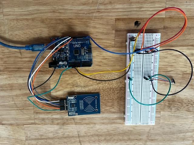
The goal is to build an RFID reader with vibration motors, which would be triggered every time a specific key card or tag passes it, resulting in the RFID reader vibrating (while stored in the belt clip), alerting the client to the existence of the object/location, i.e., a door, ultimately helping them orient themselves around an indoor space.
Supplies
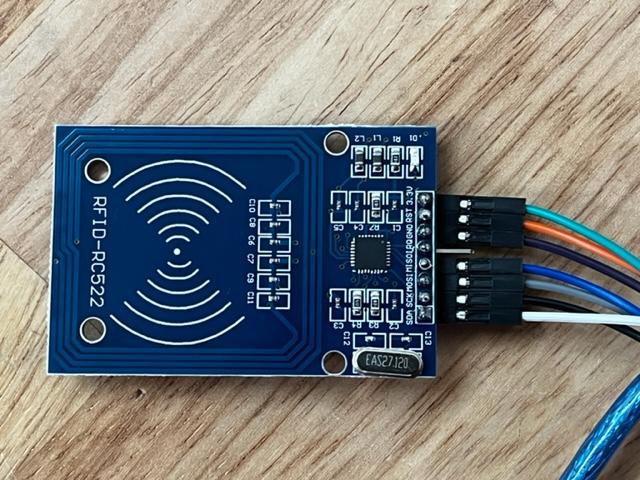
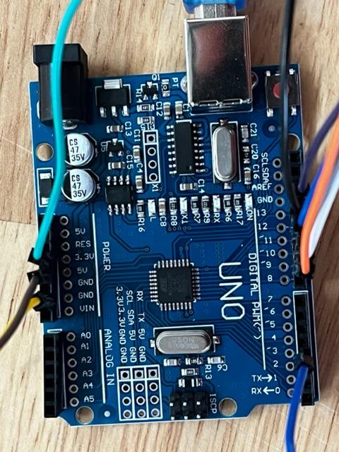
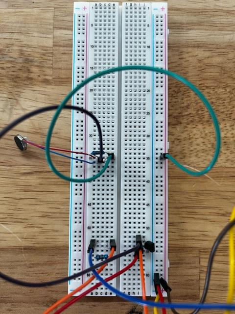
To build RFID scanner:
- Arduino Uno Rev3 Circuit Board
- RFID-RC522 and Key Card and Key Tag
- Bread Board
- Vibration motor
- 7 Male-Female Dupont Wires
- 7 Male-Male Dupont Wires
- 1.2K ohm Resistor
- 33 ohm Resistor
- NPN Transistor
Other materials:
- Arduino IDE desktop coding application
- Belt Clip (we 3D printed our own, however amazon.com has plenty of cheap alternatives)
Connecting the UNO Board and RFID-RC522 Board
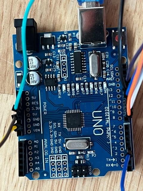
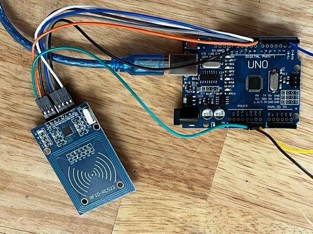
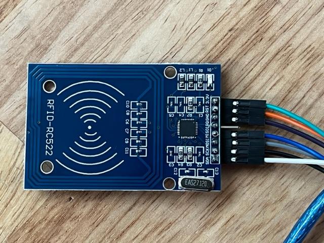
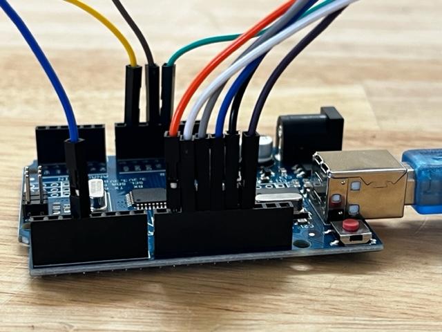
- Connect 7 Male-Female Dupont wires to: GND (in the DIGITAL PWM segment), 13, 12, 11, 10, 9, and 3.3V on the UNO circuit board.
- Now connect the Male-Female Dupont wires to these corresponding places on the RFID-RC522 board:
GND (UNO board) to GND (RFID board), 13 to SCK, 12 to MISOI, 11 to MOSI, 10 to SDA, 9 to RST, and 3.3V to 3.3V
Connecting the UNO Board to the Bread Board
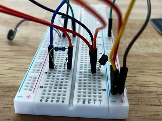
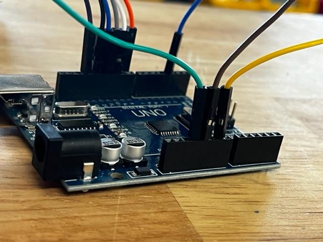
- Connect 3 Male-Male Dupont wires to: 5V, GND (in the POWER segment), and 3 on the UNO board.
- Now connect the wires from the UNO board to the corresponding places on the Bread Board:
5V to 61 (positive, on the right side), GND to 61 (negative, on the right side), and 3 to 53a
Connecting the Rest of the Bread Board to Itself
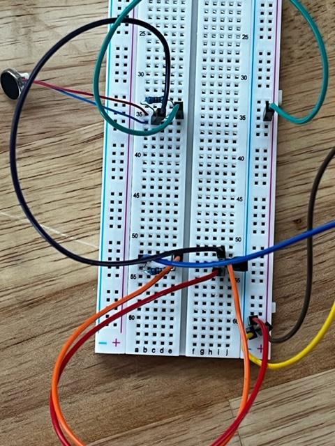
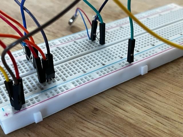
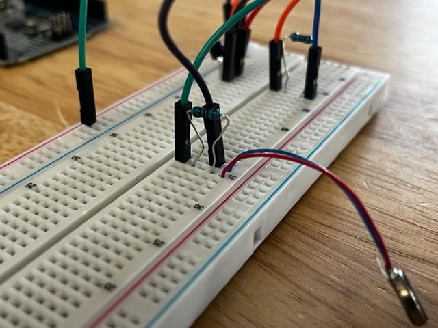
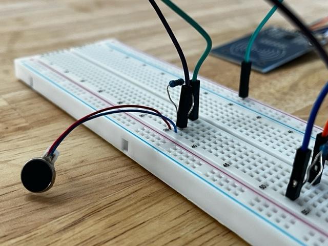
- Connect one side of a Male-Male Dupont wire to 35e and the other side to 35 (positive, right side of board)
- Connect one side of a Male-Male Dupont wire to 36b and the other side to 52i
- Connect one side of a Male-Male Dupont wire to 53e and the other side to 53i
- Connect one side of a Male-Male Dupont wire to 54i and the other side to 60 (negative, right side of board)
- Connect one side of the 1.2K ohm Resistor wire to 53b and the other side to 53d
- Connect one side of the 33 ohm Resistor wire to 35b and the other side to 35d
- Connect the red wire of the Vibration Motor to 35a and the blue wire to 36a
- Connect the first wire of the NPN Transistor to 52j, the middle wire to 53j, and the last wire to 54j
Code for the Vibration Motors
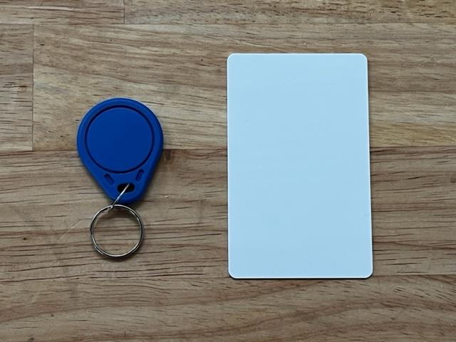
This text codes for two different kinds of vibrating patterns for two different key cards/tags.
Key Card 1 codes for a one second buzz.
Key Card 2 codes for 2 consecutive buzzes, with a half second interval between them.
Downloads
Pt. 1 - 3D Design Belt Clip (Optional)
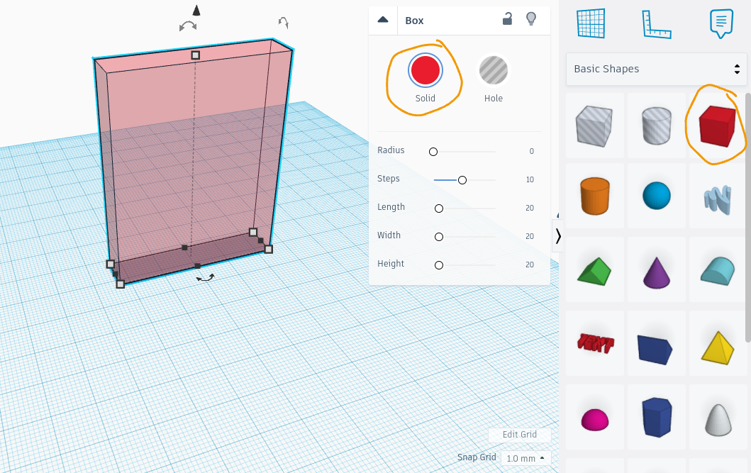
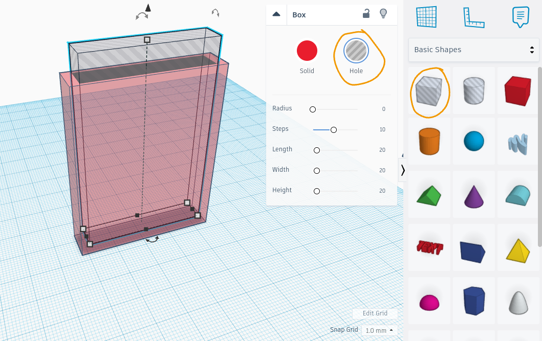
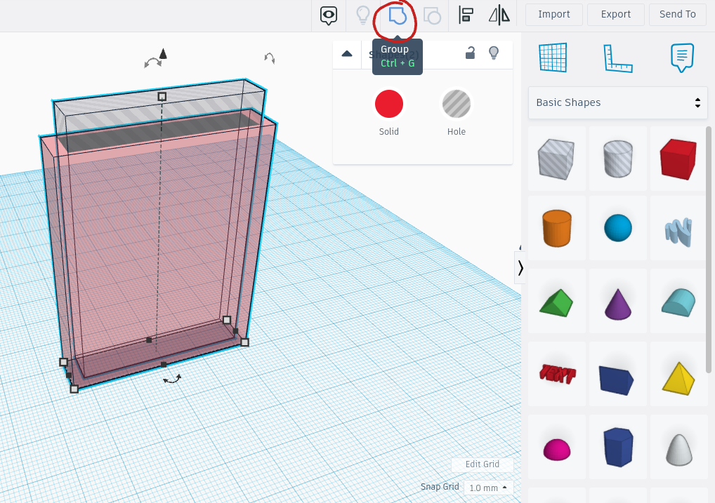
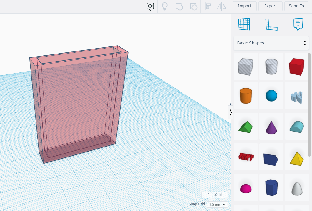
Website: tinkercad.com (very simple and easy to use)
Picture 1: Create a 3D rectangle shape by dragging a red box from the "Basic Shapes" panel onto the Workplane. Adjust the rectangle depth, height, and width using the white dots and arrows on each side. Make sure that this box is selected as a "Solid" and NOT a "Hole".
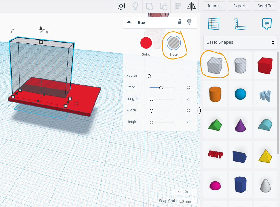
Picture 2: Create another 3D rectangle by dragging the striped transparent box from the "Basic Shapes" panel onto the Workplane, take care to check that "Hole" is selected for this shape in the pop-up bar, and NOT "Solid". Make sure this rectangle is smaller than the first one you created, and that it fits inside the rectangle with the width, height, and depth that you want the cutout to be.
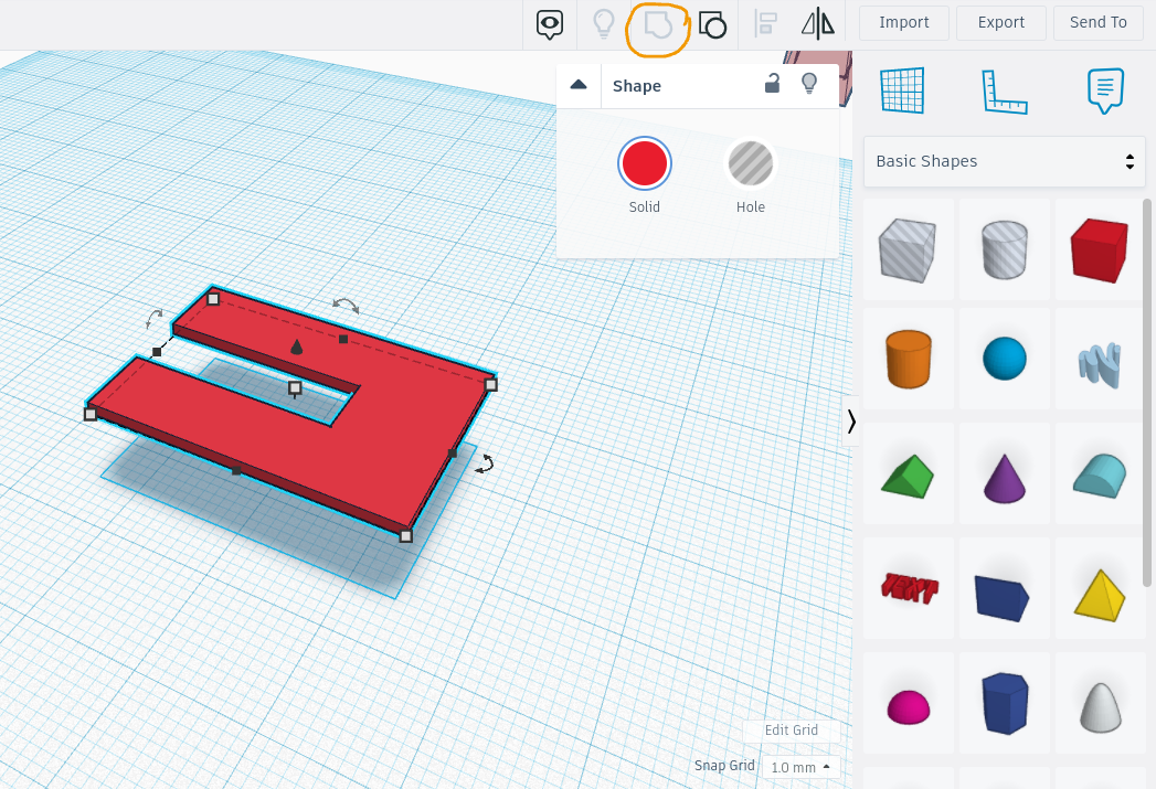
Picture 3: Select both rectangles by clicking and dragging over them, then hover to the right upper side of the panel bar and click on the "Group" button. This should result in the disappearance of the striped transparent box, and in its place an exact same hole as its shape.
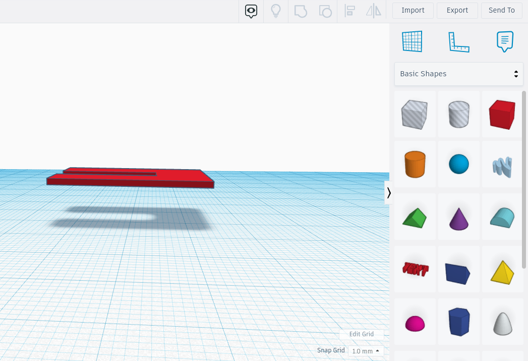
Picture 4: This is what the finished shape should look like.
Pt. 2 - 3D Design Belt Clip (Optional)
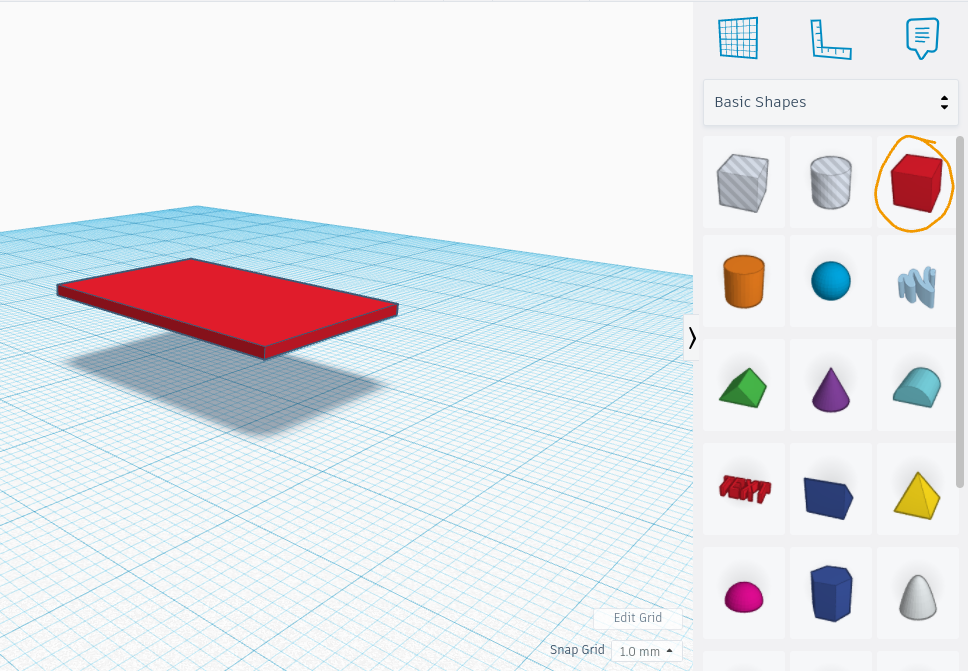
Picture 1: Create a rectangle by dragging a red box from the "Basic Shapes" panel.
Picture 2: Create a "Hole" rectangle by dragging the gray-transparent box from the "Basic Shapes" panel onto the first rectangle you made, adjust it to be about 3/4 the length of the red rectangle and then center it onto the first rectangle you made.
Picture 3: Select both rectangles by clicking and dragging over them, then select "Group" from the upper-right panel.
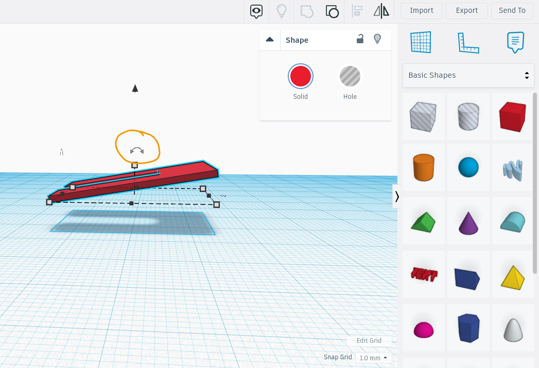
Pictures 4 & 5: Click and drag on the degree arrow to the side of the rectangle, and drag it a couple of degrees until the shape is at an angle of a bunny slope.
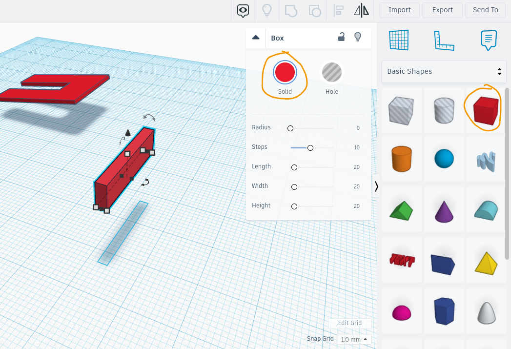
Picture 6: Create another rectangle by dragging a red box from the "Basic Shapes" panel. Resize it so it complements the length and width as the other rectangle you just made, but instead its in an upright vertical position.
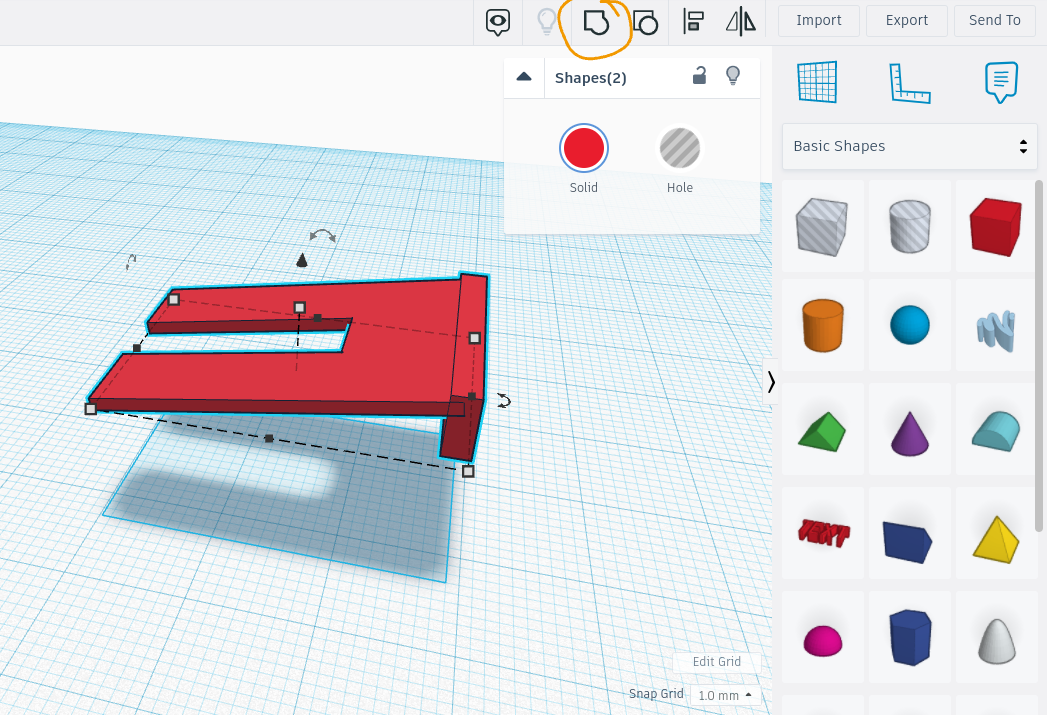
Picture 7: Select both shapes by clicking and dragging over them, then select the "Group" command in the upper-right panel. Finished look.
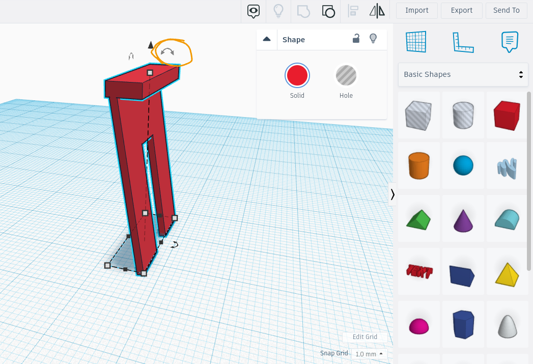
Picture 8: Click and drag on the degree arrow to the side of the shape, and drag it 90 degrees for it to be in a vertically upright position.
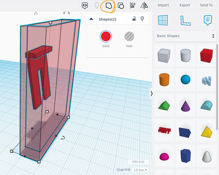
Picture 9: Align it to the backside of the belt clip pouch that you created earlier. Finished product.