RFID Mass Key Finder
This is a modular key finder using RFID. It uses magnets to stick the keys to the board. The keys can be stuck on any magnet, and it can be found through a website. The website can be interacted with and turns on LEDs above the keys to indicate their locations. It is modular because any number of key hangers can be made. My program will take an input for how many readers are available and automatically makes a wiring plan to take the greatest advantage of the limited pins on the Raspberry Pi. It does this by connecting the readers in parallel and only having separate RST pins to wake each reader, as well as Charlieplexing the LED indicators to multiply how many can be separately turned on. I made this project because my dad owns a lot of apartment units, and he needs to get the find keys to them quickly.
Supplies
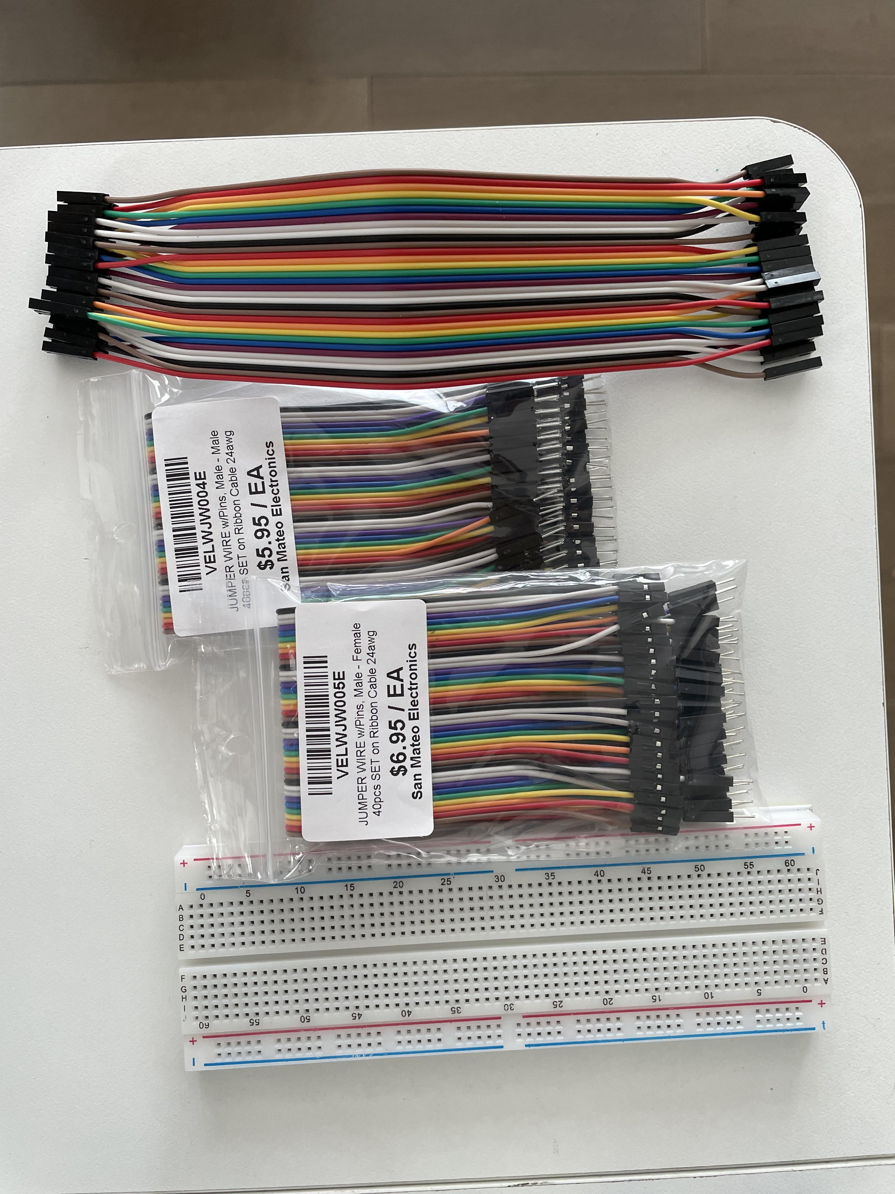
- 40 male-male jumper wires
- 40 female-female jumper wires
- 40 male-female jumpers wires
- Breadboard
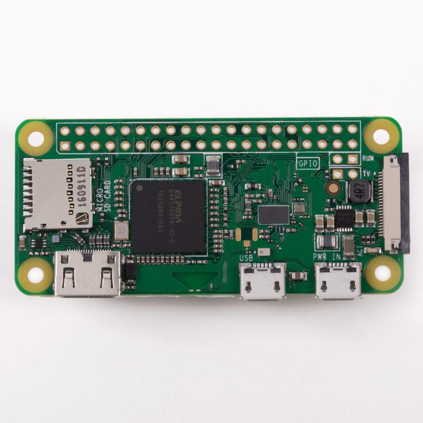
- Raspberry Pi Zero 2 W
- Power supply (pretty much any Micro-USB phone charger will work)
- header pins (skip if preinstalled on Pi)
- HDMI cable
- Mini HDMI to HDMI adapter
- 32 GB Micro SD card
- Micro-USB to USB adapter
- USB Splitter
- Monitor (any with HDMI input)
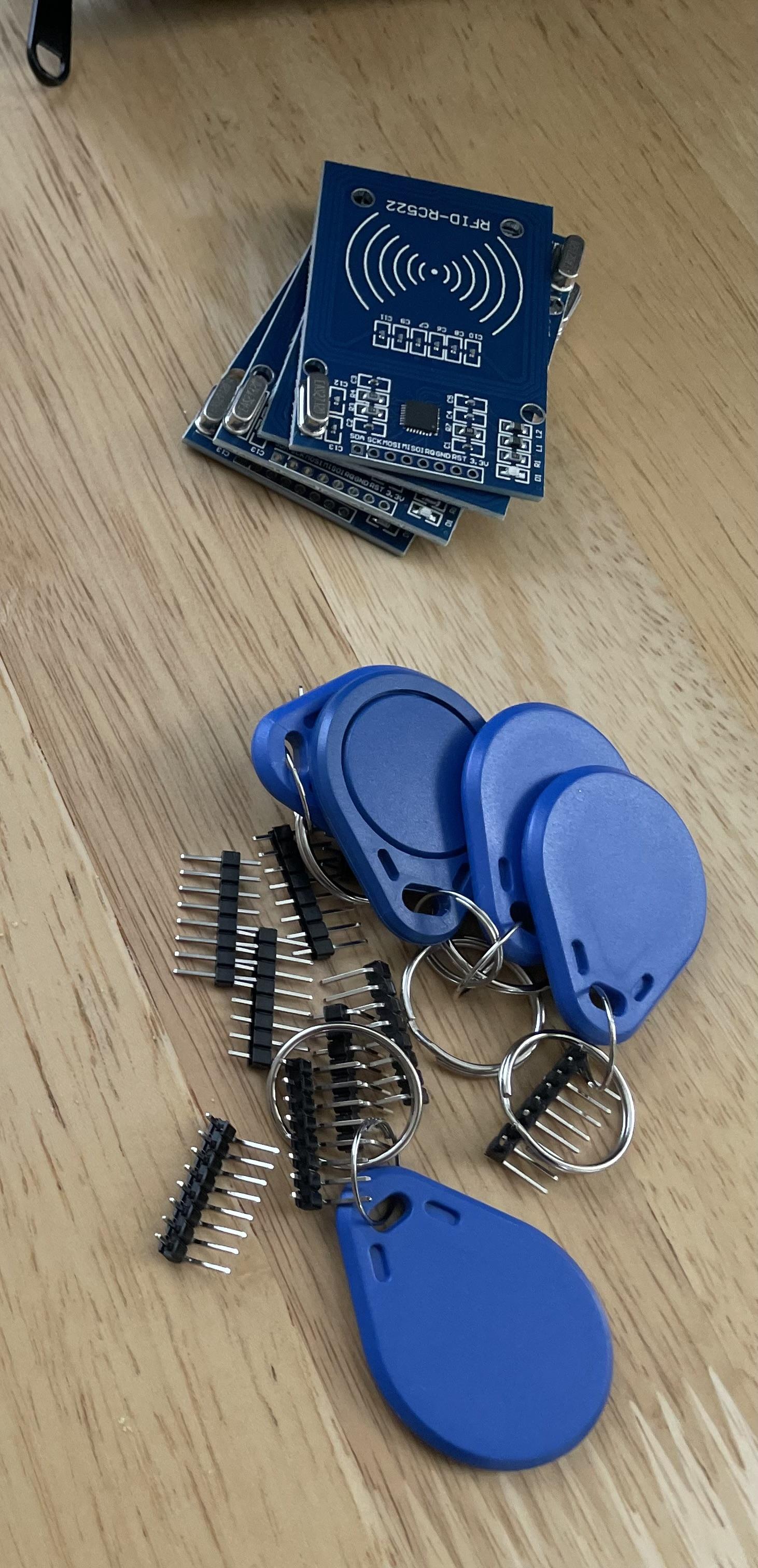
- MFRC522 RFID reader
- 3 Green LEDs
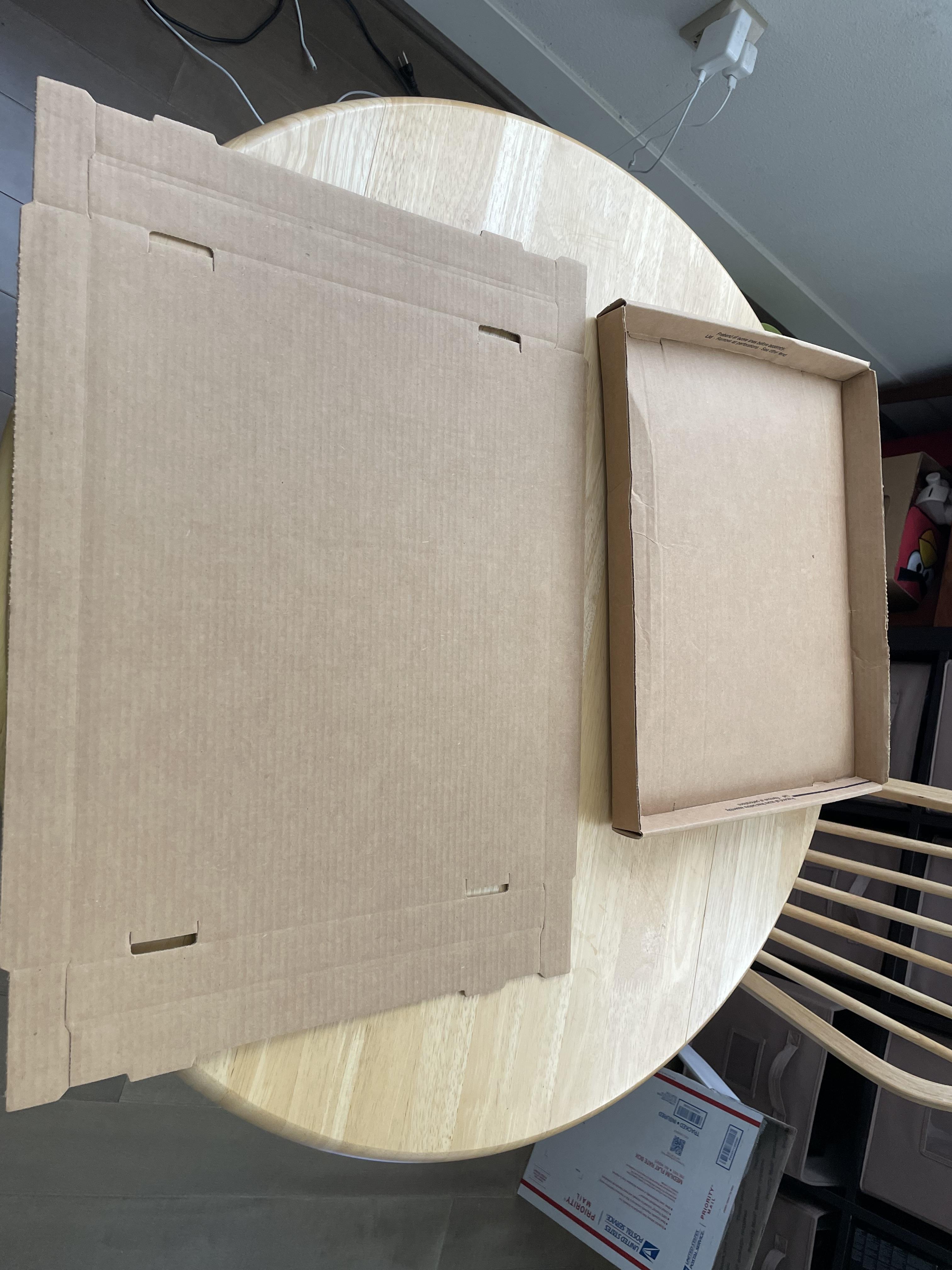
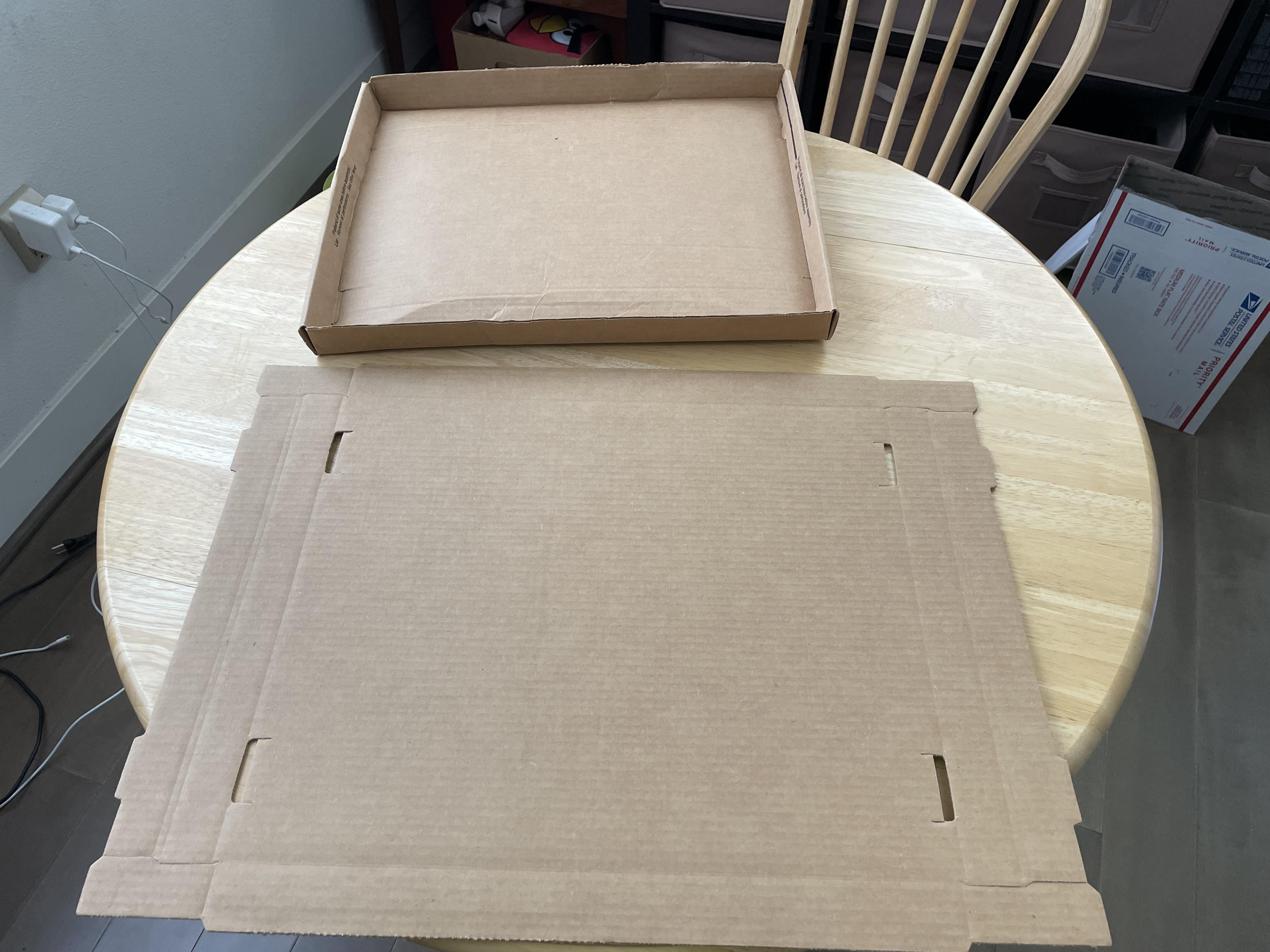
- 64 x 48 cm cardboard
- Cardboard lid at least 3 cm tall
- Neodymium magnets
- Packing tape
- Regular tape
General Raspberry Pi Setup
- If the header pins are not pre-soldered, solder them.
- Plug the Micro-USB power supply into the USB port on the right of the Pi; pretty much anything that has enough power to charge your phone will work.
- Connect Pi to monitor with HDMI; you will need to adapt it into Mini HDMI.
- Plug the USB splitter into the left Micro-USB port of the Pi using the Micro-USB to USB adapter.
- Connect a mouse and keyboard into the splitter.
- Insert Micro SD card into another computer. Install Raspberry Pi OS using these instructions.
- Go back to the Raspberry Pi.
- Set up a static IP address
- Open the LXTerminal by clicking on the icon in the top left and enter the following command:
sudo raspi-config
- Use the arrow keys to navigate to Interfacing Options and press enter. Enter the SSH and SPI menus and activate them once done:
sudo reboot
Software Setup
- Go to my GitHub to get the code to run this project.
- Click the green Code button and click Download ZIP.
- Open the Downloads folder
- Right click the ZIP file
- Right click and select Extract Here
- Open another terminal
cd /home/pi/Downloads/KeyFinder-main
sudo pip3 install -r requirements.txt
sudo apt install nodejs
sudo npm install
sudo python WriteBookInfo.py
- When prompted, type how may RFID readers you have.
- The program will return an explanation on how to wire that specific number of readers.
- Note it down
- Open two other terminal windows and put one command in each
sudo pynodered /home/pi/Downloads/KeyFinder-main/WriteBookInfo.py
sudo node-red
- Go to your Downloads folder
- open KeyFinder-main
- open flows.json
- copy it
- Open the web browser in the top left
- Go to localhost:1880
- Click the three lines icon in the top right
- Click import
- Paste in the box
- Click import
- Click deploy in the top right
Wiring
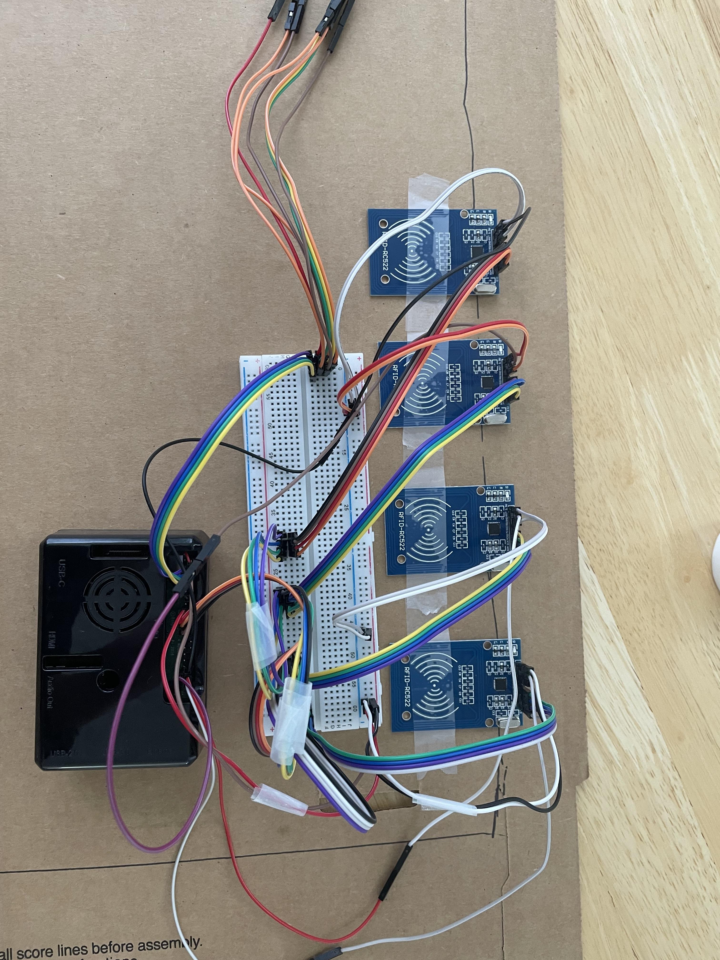
- Open pinout.xyz for reference.
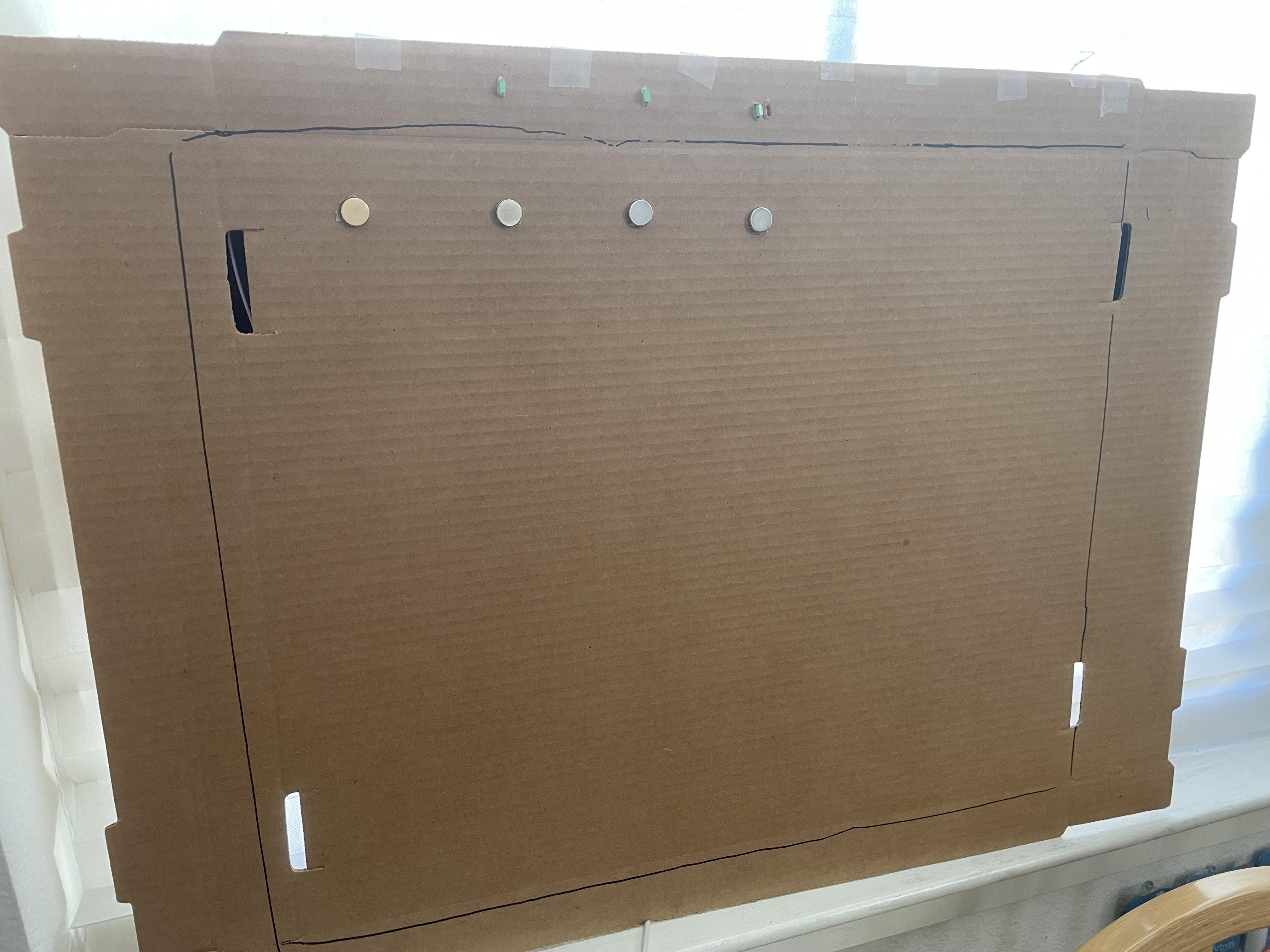
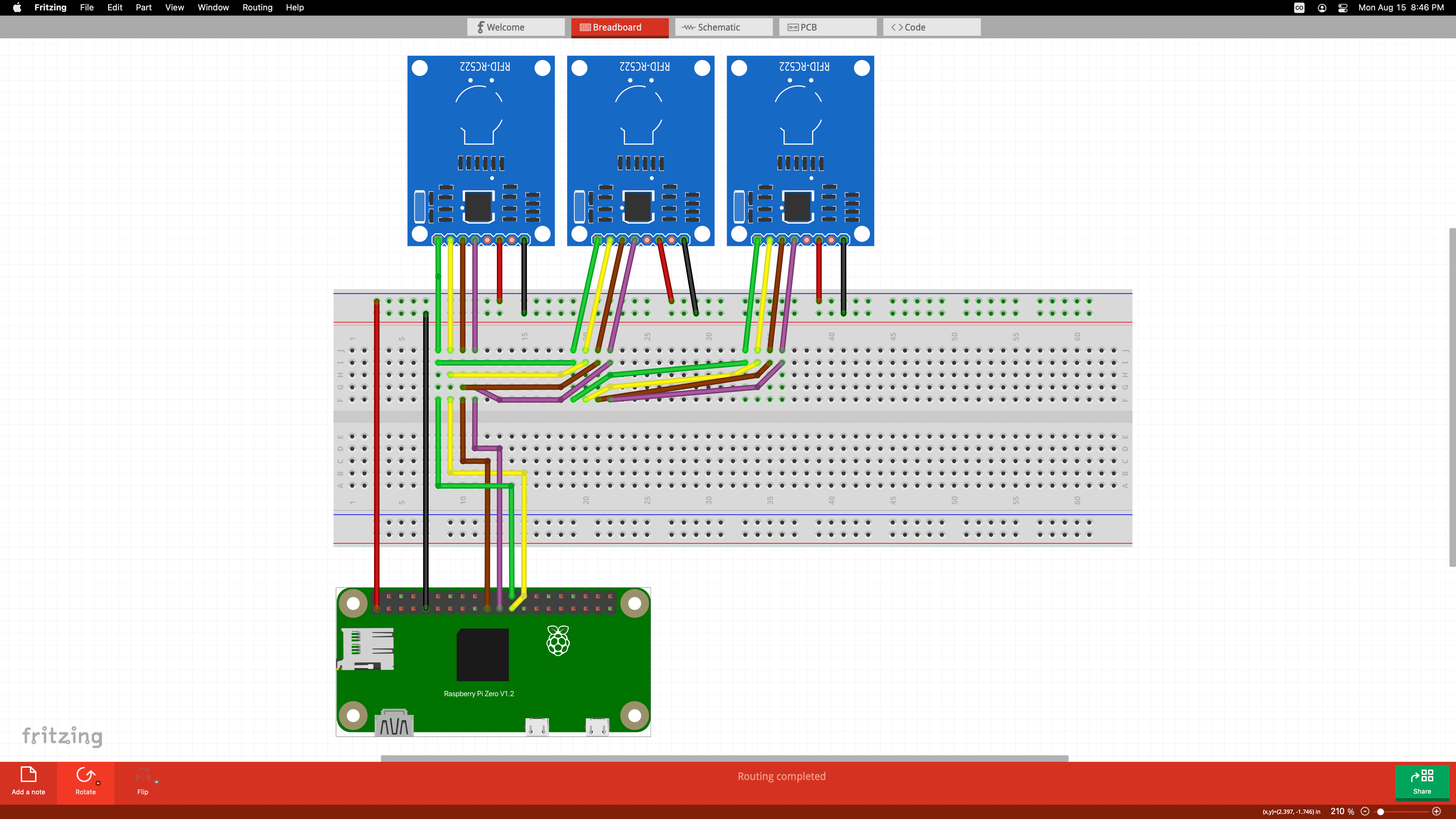
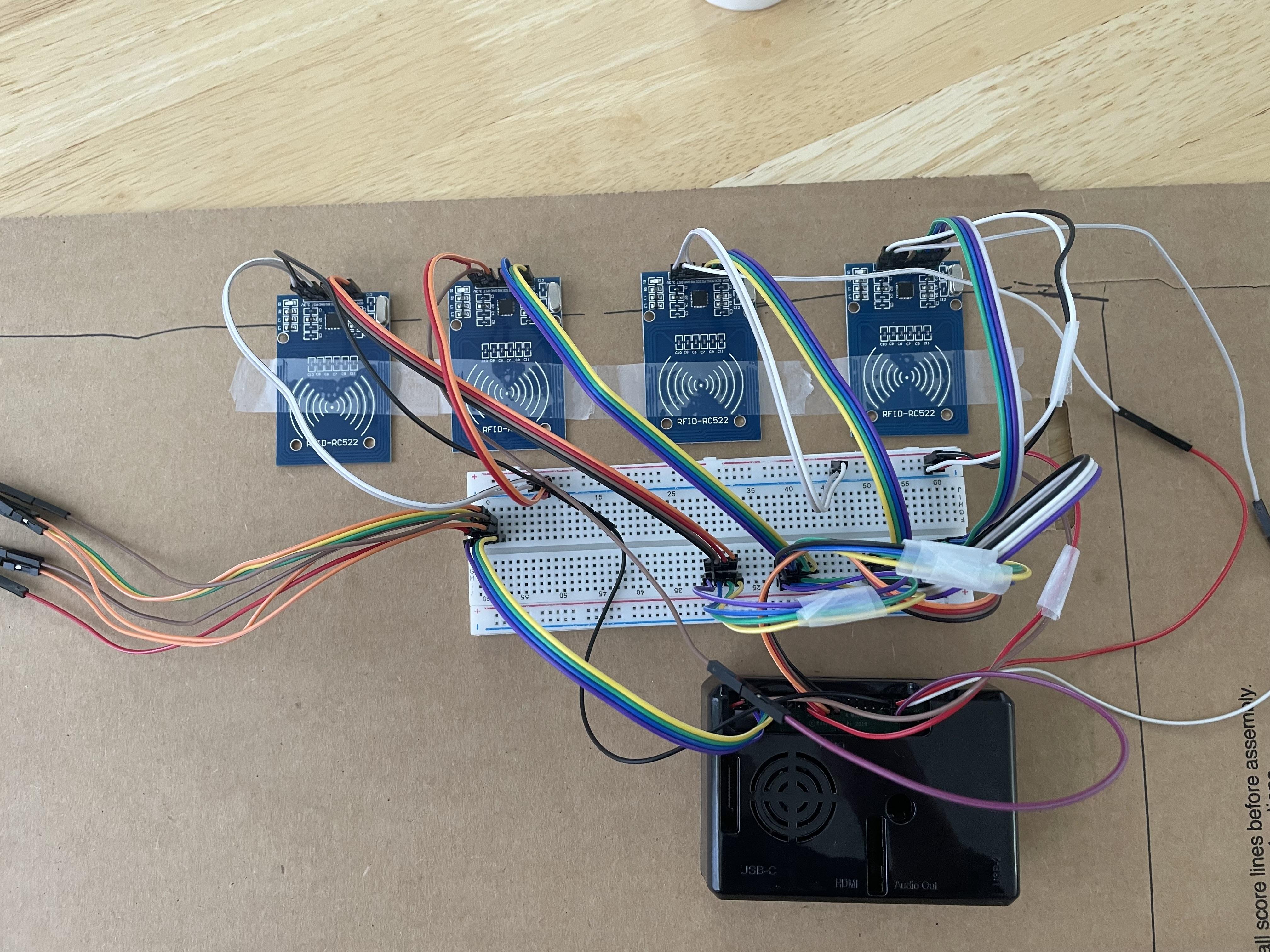
- Wire the RFID readers' MOSI, MISO, SCK, and SDA pins like in the first image.
- Follow the wiring instructions from the python script
- Note that the pin numbers in the wiring instructions are BCM numbers. On pinout.xyz, that is the number after the abbreviation GPIO.
- The numbers for the RFID readers correspond to which Raspberry Pi GPIO pin the RST pin of the reader should be connected to. The RST pin is the second one from the right between the VCC and GND.
- The number pairs for the LEDs show which Raspberry Pi GPIO pin the LED should be connected to. The first number of each pair is the Cathode connections, while the second is the Anode connection. The first pair represents the connections of the LED that should be placed above reader1, the second pair is the LED for reader2, and so on.
Assembly
- Get the cardboard about 64x48 cm and a cardboard lid at least 3 cm high.
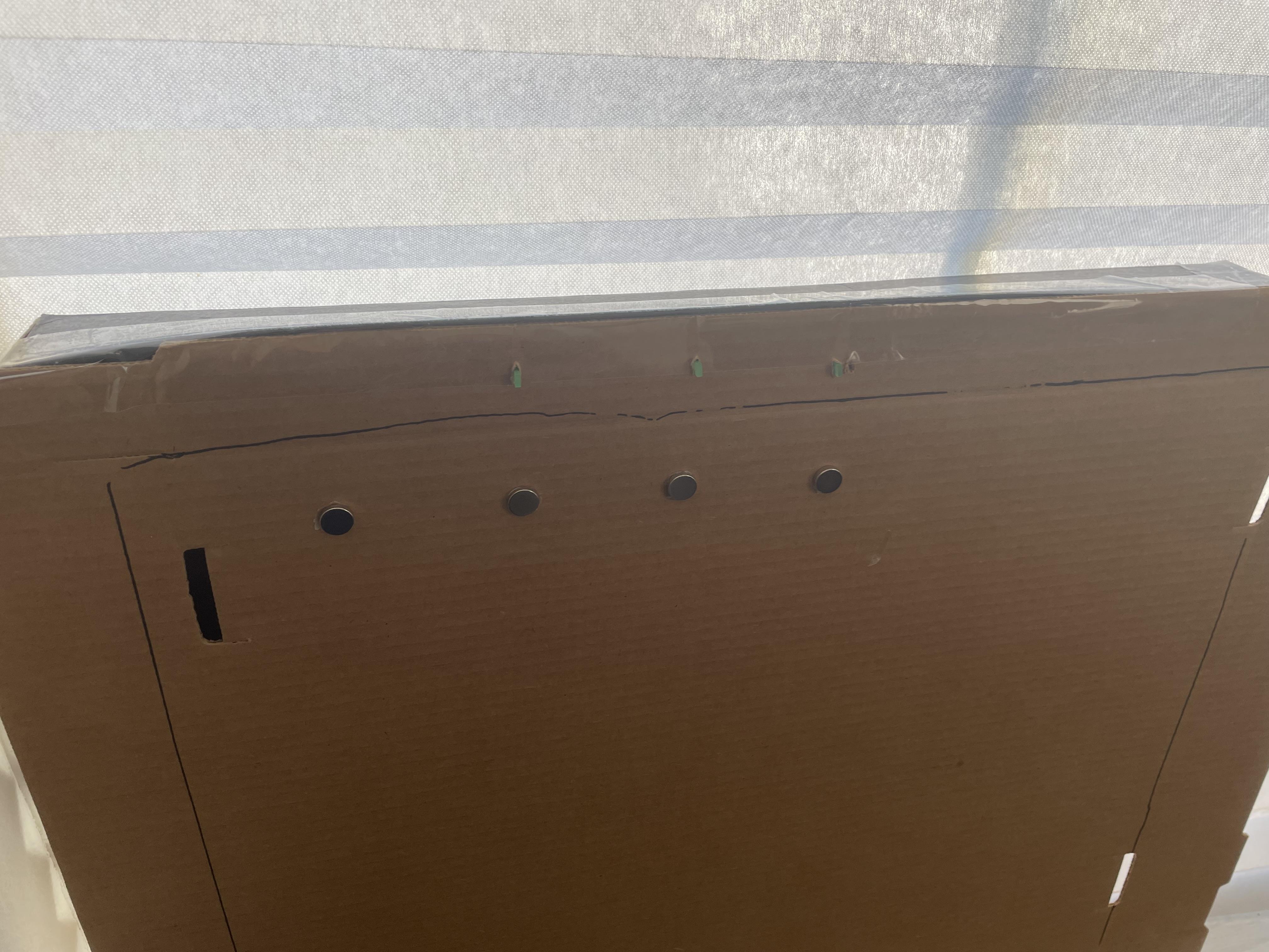
- Glue the magnets where you want the keys to be
- Flip the cardboard
- Find where the magnets are on the other side and attach the RFID readers to those spots.
- Make sure to have the reader marked as 'reader1' is in the top right corner.
- Peel the adhesive off the breadboard and stick it on
- Tape the Raspberry Pi to the back.
- Poke holes above each reader and insert the LED through.
- Wires may need to be added to make this work.
- Attach the lid to the back with packing tape or some other material, covering electronics
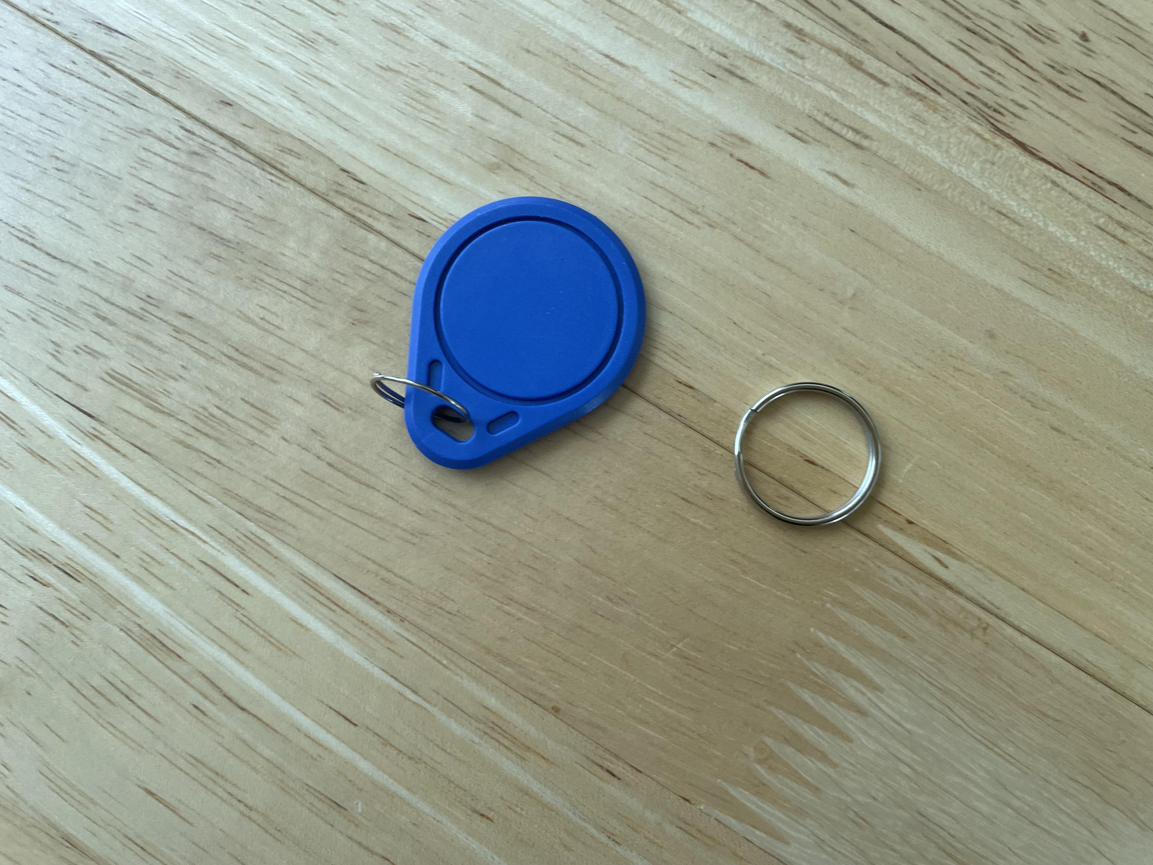
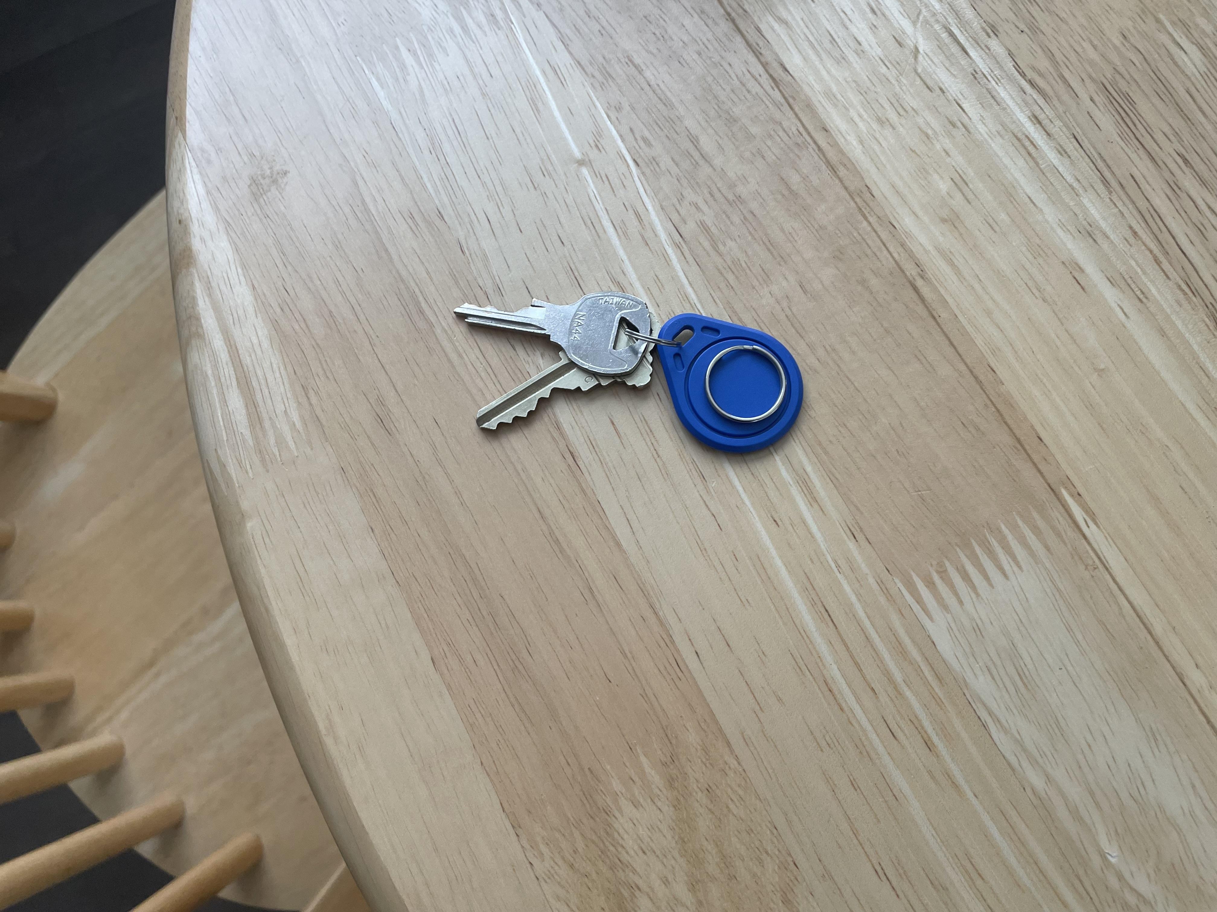
- Get the RFID tags.
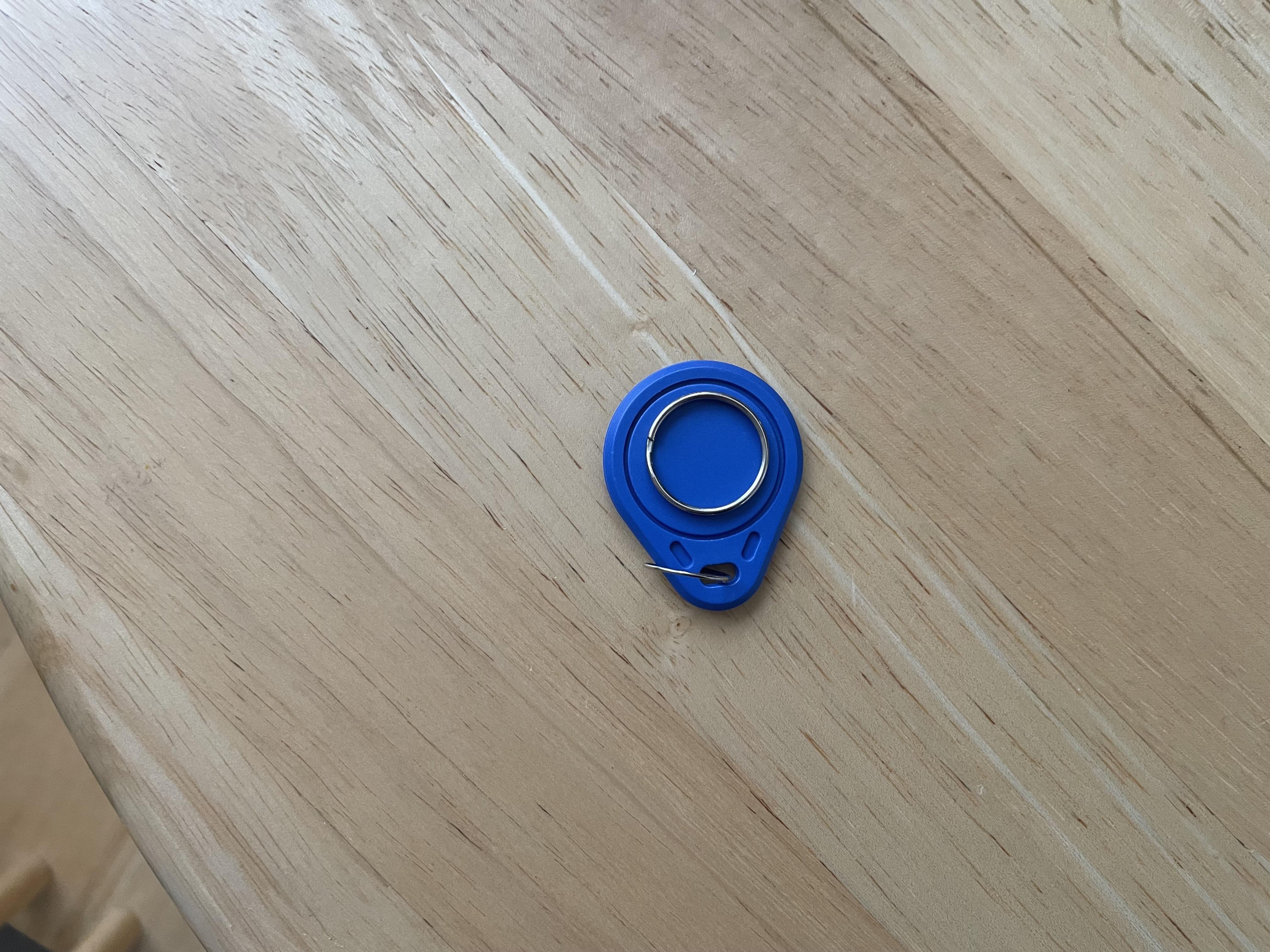
- Take the larger key ring off and glue it to the face of the tag
- Flip it back around to confirm LEDs are poking through
- Highlight the top left magnet to remind yourself that it is the input magnet.
Testing
- Go into your router settings. And set up port forwarding your public IP on port 1880 to the static IP of the Raspberry Pi you set in the first step on port 1880. Every router is different, so I have no specific instructions on how to do this.
- Open a browser on another computer and type in your routerPrivateIP:1880/ui
- Stick a tag to the top left magnet
- Type in desired details in the input form and submit
- Move the tag to another magnet
- If the details appear in the table under Keys List, then it is a success
- If something is not working, do some troubleshooting, and then if it is a program bug, open an issue on the Github repository.