RFID Internet Radio
by tars.vanhoof in Circuits > Raspberry Pi
6008 Views, 158 Favorites, 0 Comments
RFID Internet Radio
Hello fellow makers,
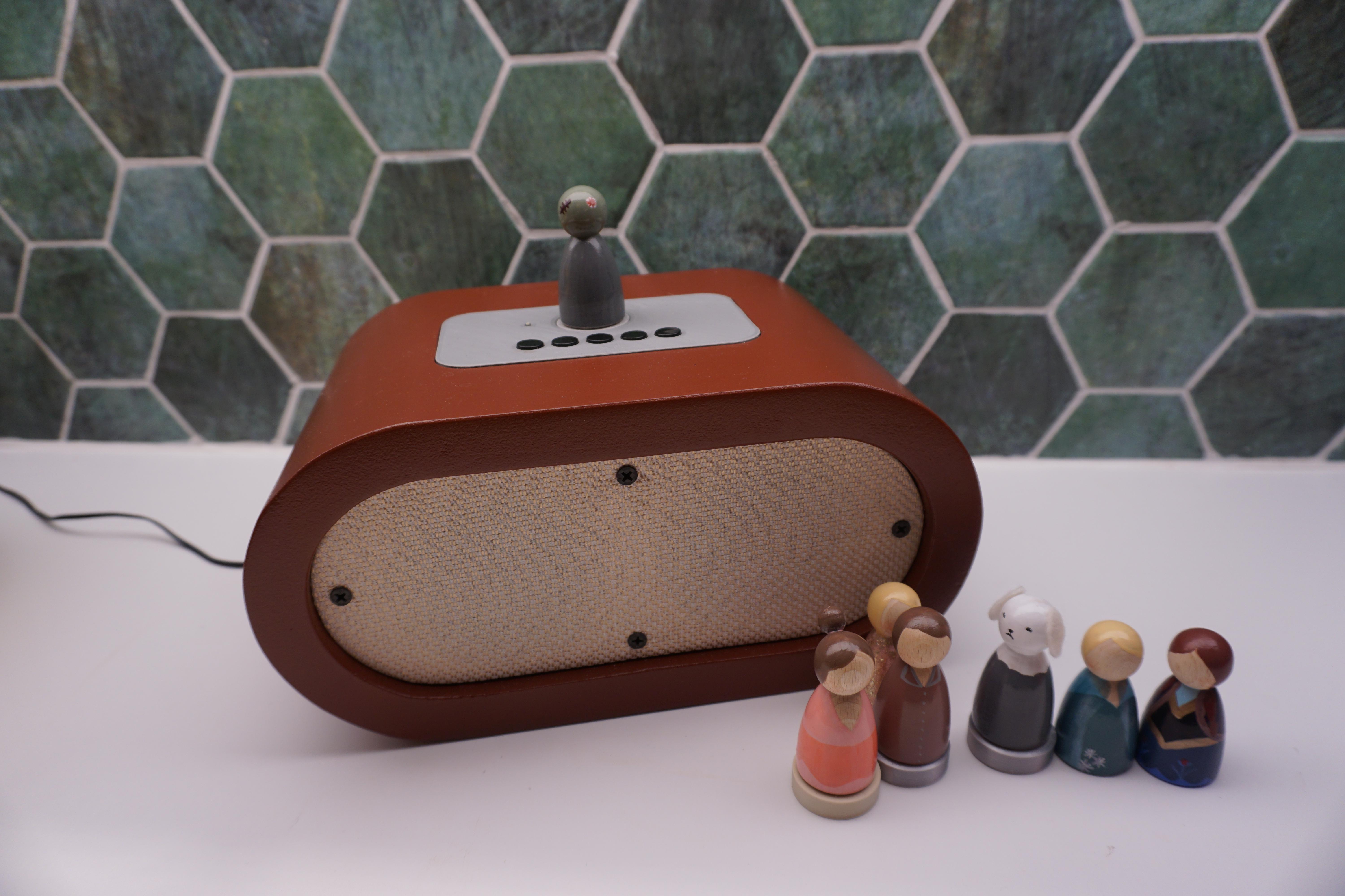
This Instructable describes how I made an RFID internet radio for my kids. They like to listen to music but since they're too young to start Spotify and cast to the TV themselves, I decided to make an easy and hopefully fun interface for them. This was a Covid-19 project so I took my time.
The player is built with a Raspberry Pi, a HiFi module and an RFID module. The tags are put in a base on which wooden puppets are glued which are easily identifiable for the kids as containing a certain playlist. I also designed and built a nice enclosure because it will be visible in our living room and therefore it has to look good.
I made a lot of personal choices during the development but because it's built around a Raspberry pi it's very customizable. I'll try to describe my progress and all the problems I encountered as detailed as possible.
I've already got a few upgrades in mind such as removing the (need for) buttons to make it even simpler, I'd like even better full-range speakers, playlist programming via a smartphone, maybe in the long run easier set-up of WiFi and Spotify for non-Raspberry-savvy family members...
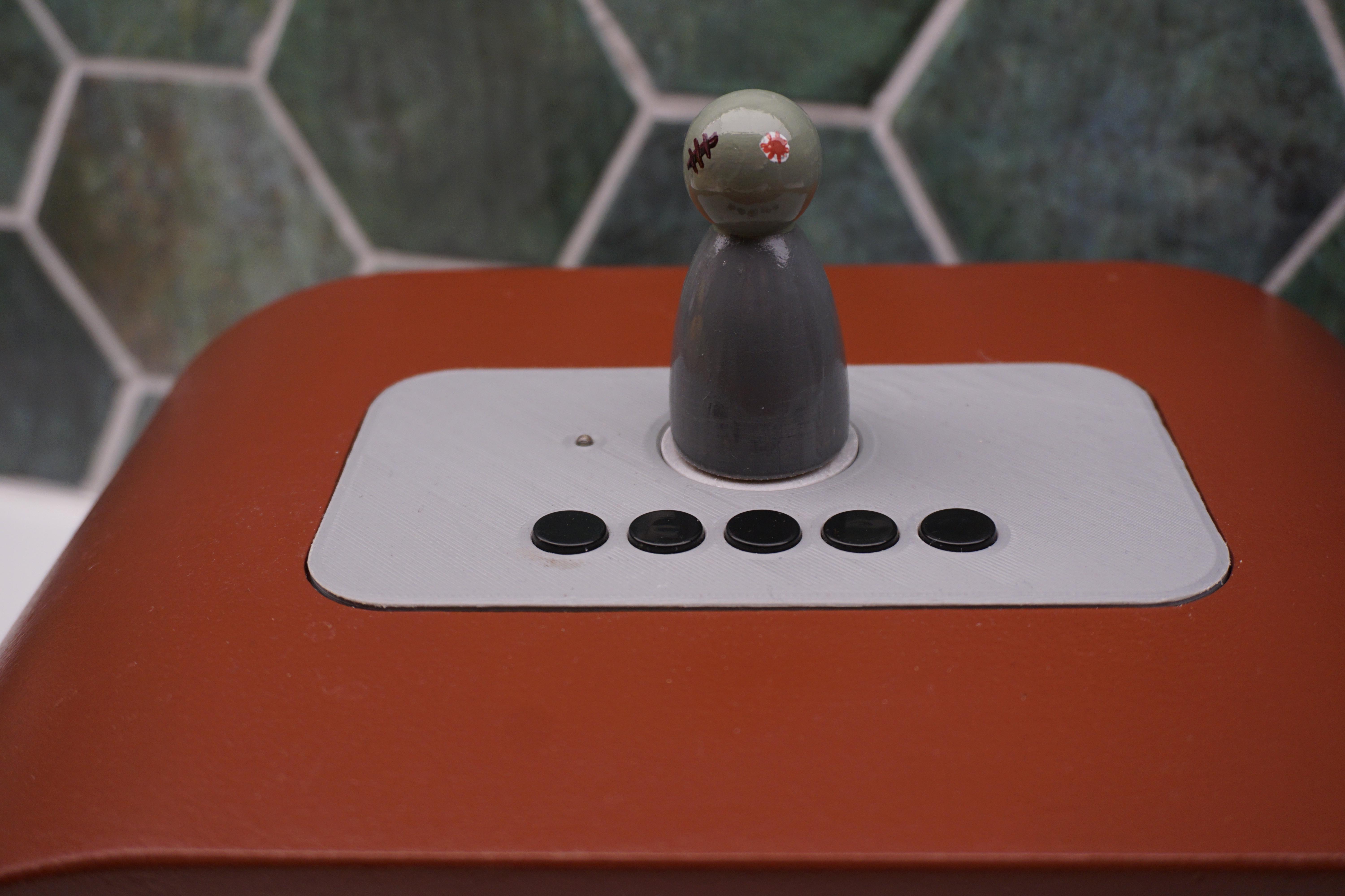
I'd love to see what others make of it! Can you guess which song the puppet on top is for?
Supplies
For the electronics:
- A Raspberry Pi. I developed this first on an old v1 but upgraded to a v3 because of the HiFi module's compatibility). The SD card should be big enough, I ran into storage problems with a 2GB one and I upgraded to 32GB because I had that lying around;
- A HiFi module. The one in this project is one from Banggood but there are alternatives like Justboom or Hifiberry. I'd have loved to try the Justboom module but it wasn't in stock at the time. You need access to the GPIO pins with the HiFi module attached. I saw after ordering that the manual of this module says they cannot be used anymore, but after testing they worked fine anyway;
- An RFID module. I got an RC522 with a few tags for testing, also from Banggood;
- Speaker(s) that match the output and resistance requirement of the HiFi module. I scavenged mine from a broken PC gaming surround set;
- A power supply that suits the HiFi module. Also rescued but this was from an old WiFi router;
- Buttons for play/pause, stop, next, volume up and down (in hindsight I've implemented too many but more on that below);
- An LED (+220Ohm resistor) as ready to play indicator;
- Some wire and connectors to wire everything together.
- A bunch of compatible (!) RFID tags. Mifare 1k did the trick for me.
For the casing:
- 25 mm MDF (1" for overseas maker colleagues)
- 4 mm plywood or MDF for the speaker plate (1/8"). I used scrap wood I had laying around
- Speaker fabric
- Hot glue gun
- Wood screws (I used matte black drywall screws because I liked their look better)
- MDF filler
- Wood laquer
The Electronics
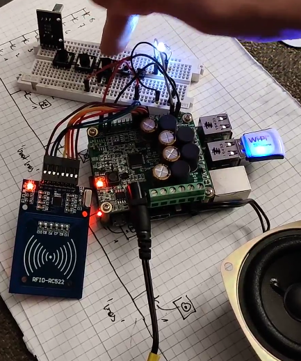
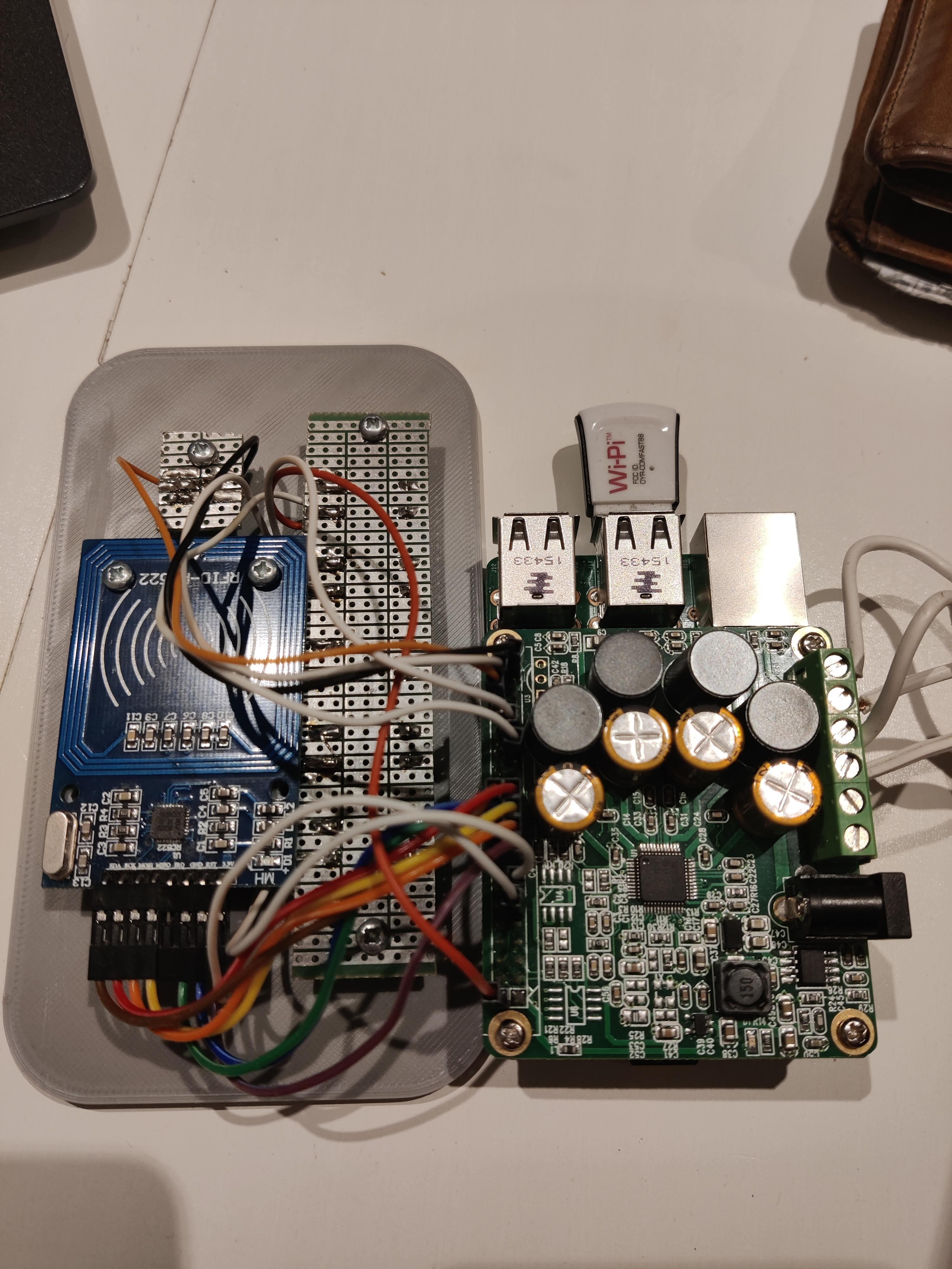
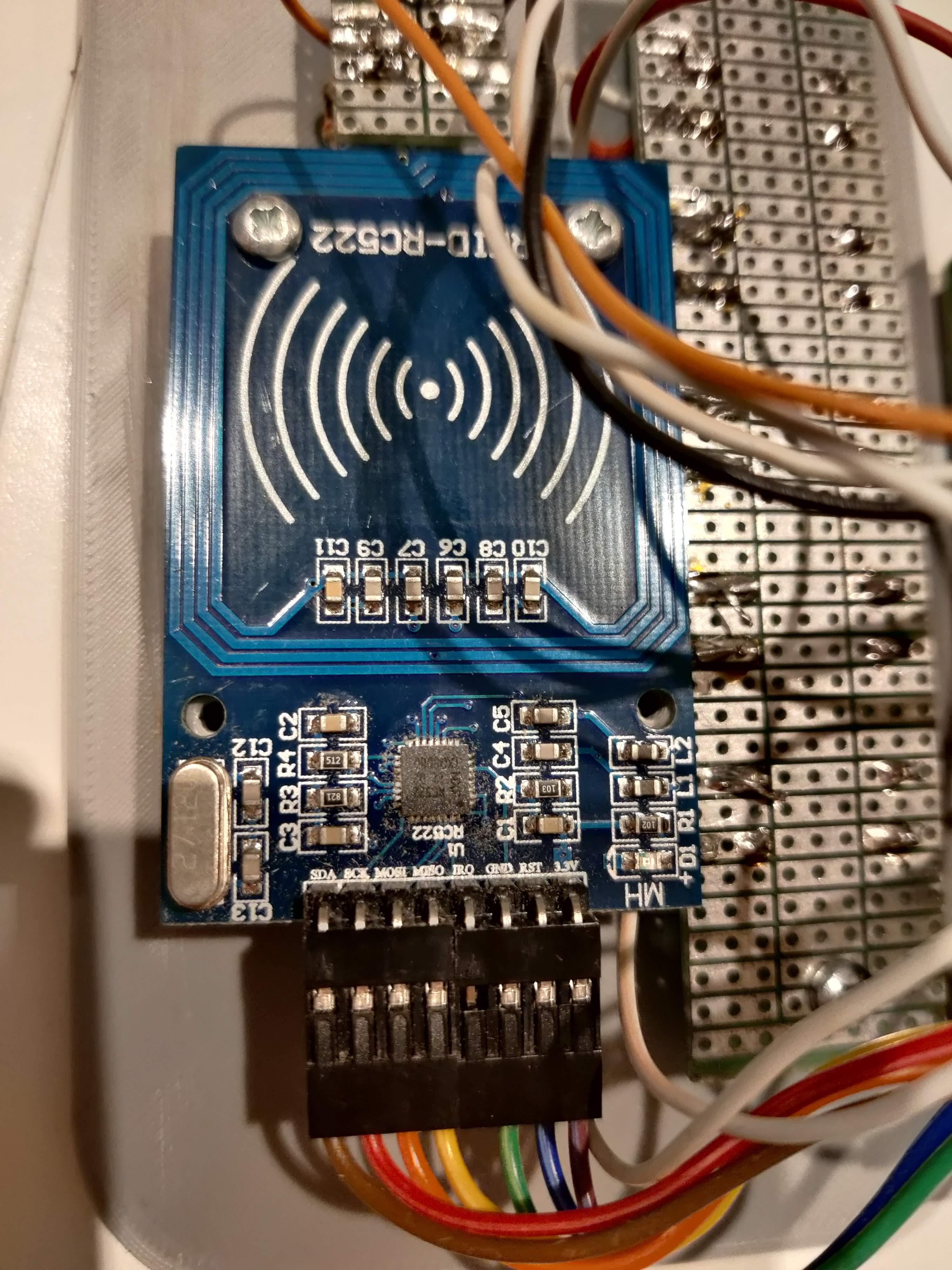
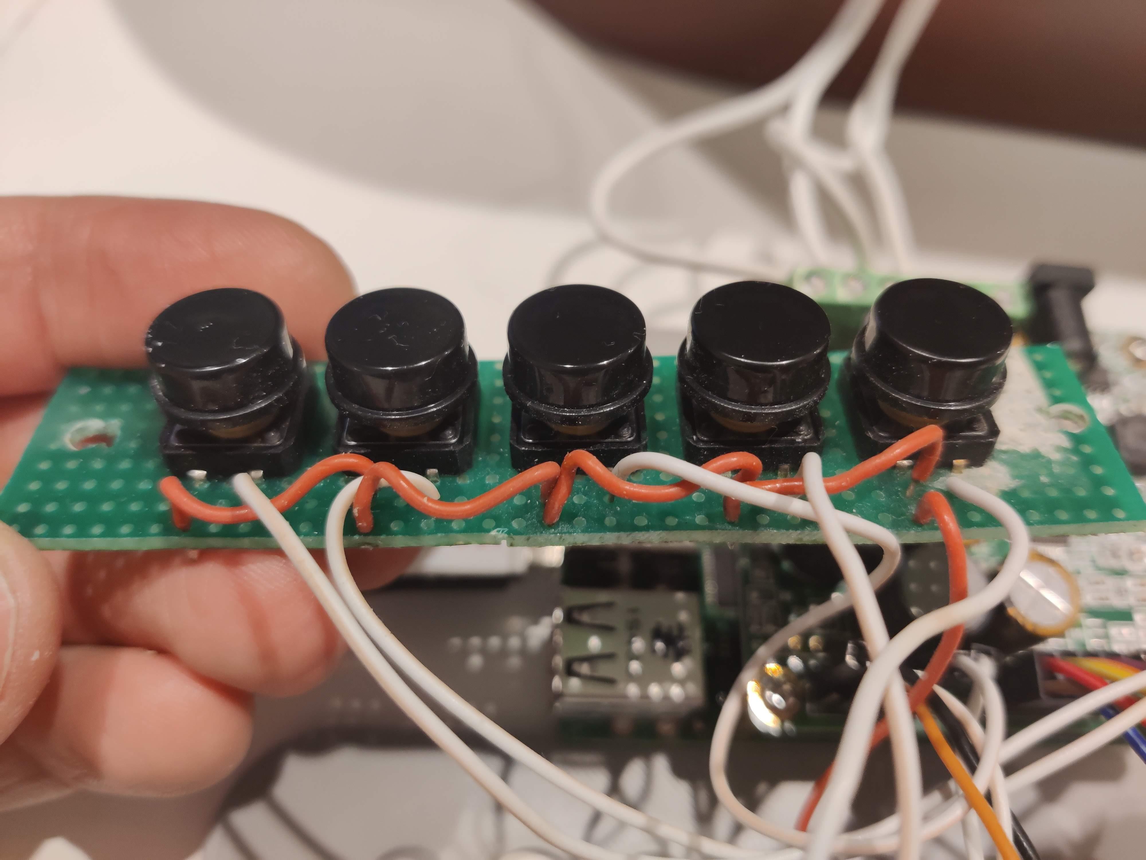
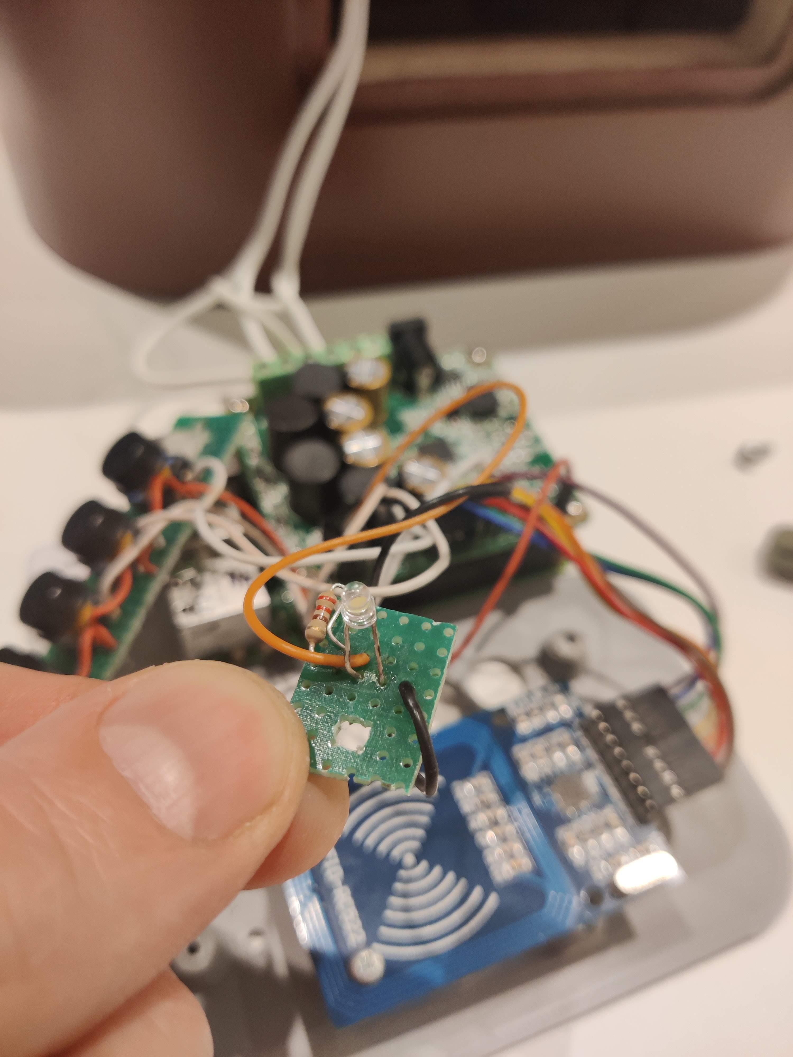
Once you have decided on the HiFi and RFID modules, you get to branch everything together for the first time. I think this is one of the most fun parts besides watching the kids play with their new toy when it's finished. Unless you release the magic smoke that is (never happens to me)...
The HiFi module can just be pressed on the GPIO header and it comes with metal standoffs for nice and sturdy attachment. As mentioned before, the HiFi module's manual says that it renders the GPIO pins unusable, but this has proved not to be the case. The module also powers the Pi which eliminates the need for more than one power supply and makes wiring a lot easier.
The NFC module requires some cabling, for which I followed this guide but I changed the 3.3V and GND pins to be able to use a single 4x2 connector on the Pi's side:
- GPIO 17 to 3.3V
- GPIO 19 to MOSI
- GPIO 20 to GND
- GPIO 21 to MISO
- GPIO 22 to RST
- GPIO 23 to SCK
- GPIO 24 to SDA
The buttons all use the internal pull-down resistors of the raspberry pi so they should be wired so that they provide 5V to the corresponding pin when pushed. For this I made a custom circuit board that spaces the buttons evenly, distributes the 5V of the Pi to all buttons and can be attached to a 3D printed controls plate (more on this later). This means:
- GPIO 2 or 4 to the first button and branched (with jumpers) to the other buttons (5V)
- Play/pause button to GPIO 38
- Stop button to GPIO 31
- Next button to GPIO 33
- Vol up button to GPIO 11
- Vol dn button to GPIO 13
And as an indicator that shows that the radio is ready to start playing I added an LED on a separate circuit board. It's attached to GPIO 36 and has a 220Ohm resistor connecting it to ground on the negative lead.
The Software
Okay, here we go... This took many nights (and some days) to complete since I had to learn a lot. I documented this on the go but I hope I can make this clear enough.
Starting with the basics:
1. Install Raspberry Pi OS Lite on an SD card with Win32DiskImager or an alternative for Mac or Linux. You can download the image here and find a description on how to install it, or you can use the Raspberry Pi imager. As I mentioned before, a 2GB SD card will not be enough, but 32GB isn't necessary either.
2. Enable ssh by placing a new empty text document called ssh but without extension on the root of the SD card. This method is described in step 3 of the linked page.
3. You can also make it connect to WiFi automatically by placing a text configuration file on the root of the SD card. The file has to be called wpa_supplicant.conf and you should add this text adjusted to your country code and network:
ctrl_interface=DIR=/var/run/wpa_supplicant GROUP=netdev
update_config=1
country=BE

network={
 ssid="YOUR_SSID"
 psk="YOUR_PASSWORD"
}
4. Log in via SSH with Putty. I use an app called Fing on my phone to find the IP-address of the Pi (DCHP is on, you could also give it a static IP address). Default user is 'pi' with password 'raspberry'.
5. Change the password for the main user. Since you'll connect to WiFi you'll want to change it so not just everyone can log in via ssh. Do this by typing the command 'passwd' when logged in as pi. Do not use 'sudo passwd' because you'll change the root password instead of the user password.
6. Expand the Pi's file system by typing 'sudo raspi-config' and selecting option 1 - expand filesystem. You should probably reboot the Pi afterwards by typing 'sudo reboot'.
7. Update and upgrade all packages by typing:
sudo apt update && sudo apt upgrade
Installing Mopidy, the Linux media player which serves as the base for our radio
8. The full guide to installing Mopidy can be found here. Raspberry Pi OS is based on Debian so you'll need to follow the steps for Debian (each line is a seperate command):
wget -q -O - https://apt.mopidy.com/mopidy.gpg | sudo apt-key add -
sudo wget -q -O /etc/apt/sources.list.d/mopidy.list https://apt.mopidy.com/buster.list
sudo apt update
sudo apt install mopidy
9. Install the Mopidy Spotify extension:
sudo apt install mopidy-spotify
10. Now we have to configure Mopidy and the Spotify extension. We'll configure Mopidy to start as a service on startup, which means we have to create a configuration file in /etc/mopidy/mopidy.conf. To do this type:
sudo nano /etc/mopidy/mopidy.conf
And add or change the following sections for HTTP and Spotify:
[http]
enabled = true
hostname = 127.0.0.1
port = 6680
zeroconf = Mopidy HTTP server on $hostname
allowed_origins =
csrf_protection = true
default_app = mopidy

[spotify]
enabled = true
username = YOUR_USERNAME
password = YOUR_PASSWORD
client_id = YOUR_CLIENT_ID
client_secret = YOUR_CLIENT_SECRET
bitrate = 160
timeout = 10
cache_dir = $XDG_CACHE_DIR/mopidy/spotify
We enable the http service because that's the way our script will send commands to the music player service. Of course you should enter your own Spotify user and password but beware, this will not be hashed and remains in the files as plain text. For the client_id and client_secret values, you have to authenticate Mopidy with Spotify which can be done here. The webpage will then show you the correct values.
11. Make Mopidy start on boot of the Pi by typing the command:
sudo systemctl enable mopidy
Audio hardware setup
12. The following step is heavily dependent on the hardware you've chosen. I can only describe the necessary steps for my hardware but I assume they're quite similar for other amps. I wrestled a lot with this but eventually I found the solution in the manual; the module I bought has to be configured like a HiFiBerry. To do this, open /boot/config.txt:
sudo nano /boot/config.txt
Remove the line:
dtparam=audio=on
And add the line:
dtoverlay=hifiberry-amp
13. Reboot the Pi with 'sudo reboot'.
Testing Mopidy and http commands with Postman
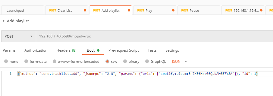
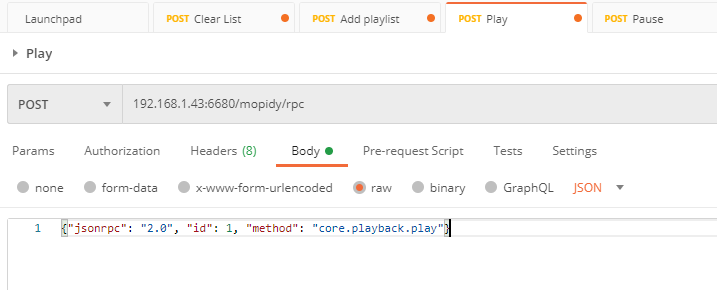
14. If you have done everything right and attach a speaker to the module, you should now be able to start playing some music remotely. For testing, and getting to know http post commands really, I used Postman. I really had to dive into the core API description of Mopidy in order to get the commands to work because I had no experience with this kind of thing. But eventually I figured it out with some help from my brother. Watch the images for the correct settings, I added examples for adding to Mopidy's tracklist and for starting playback.
As soon as you add songs to the tracklist, you should get a response from Mopidy containing all the tracks you added. And when you send the play-command the music should start playing almost immediately. There are already a lot of links in the chain so troubleshooting can take a while. If you get no sound, be sure to check the amp hat's configuration by playing a test sound. Maybe try with something plugged in the Pi's audio jack too.
If you don't get '200 - OK' response codes in Postman, there is a connection error and you should check the IP address, port and Mopidy's config file.
If you do get an '200 - OK' response code but an error in the feedback, there might be a problem with the post command or the format it's in.
Setting everything up for the RFID reader and the Python script
I leaned heavily on the PiMyLifeUp blog for this part. Credit where it's due.
15. Enable SPI on the GPIO pins by typing 'sudo raspi-config' and selecting 5 Interfacing Options - P4 SPI.
16. Reboot the Pi with 'sudo reboot'. If the RFID module is connected correctly it should now be detected by the Pi. If you enter the next command you should see a device 'bcm2835' present:
Lsmod | grep spi
17. Install Python because we need to run a script that checks the RFID reader and sends the correct commands to Mopidy:
sudo apt-get install python3-dev python3-pip
18. Install SPI libraries for Python:
sudo pip3 install spidev
19. Install the RC522 libraries for Python:
sudo pip3 install mfrc522
The script
20. This is the magic part that links everything together. I'm giving you the code in one go, I added some comments to make it clear and if you really want to know more about what's happening, send me a message and I'll be glad to explain the details later. I don't know if this is the best way to program this but I just went with something that works. I'm sure someone with more experience can make it more efficient, more stable, launch race cars into orbit, ... but for my first applied Python script I'm pretty frikkin' happy with it.
You should put the script in a location that makes sense. I put mine in /home/pi/RFID_Radio/. You create it with your favourite text editor, such as nano:
sudo nano /home/pi/RFID_Radio/RFID_Radio.py
You get an empty text document in which you can paste the following script:
#!/usr/bin/env/ python

#imports
from time import sleep
import RPi.GPIO as GPIO
import requests
from mfrc522 import SimpleMFRC522


#variables/instances
reader = SimpleMFRC522()
previoustext = ""
text = ""
url = "http://localhost:6680/mopidy/rpc"
volume = 30

btn_play = 38
btn_stop = 31
btn_next = 33
btn_vol_dn = 13
btn_vol_up = 11
led_active = 36


#function definitions
def play_pause(channel):
        #get current playback state first
        r = requests.post(url, json={"jsonrpc": "2.0", "id": 1, "method": "core.playback.get_state"})

        if r.text.find('playing') == -1:
                #not playing, go to play
                requests.post(url, json={"jsonrpc": "2.0", "id": 1, "method": "core.playback.play"})

        else:
                #playing, go to pause
                requests.post(url, json={"jsonrpc": "2.0", "id": 1, "method": "core.playback.pause"})

def next(channel):
        #play next track
        requests.post(url, json={"jsonrpc": "2.0", "id": 1, "method": "core.playback.next"})

def stop(channel):
        global previoustext

        #stop playback, clear tracklist
        requests.post(url, json={"jsonrpc": "2.0", "id": 1, "method": "core.playback.stop"})
        sleep(0.1)

        #Clear existing tracklist
        r = requests.post(url, json={"jsonrpc": "2.0", "id": 1, "method": "core.tracklist.clear"})

        previoustext = ""

def vol_up(channel):
        global volume

        #increase volume but not higher than 100
        if volume == 0:
                volume = 1
        elif volume == 1:
                volume = 10
        elif volume == 100:
                volume = 100
        else:
                volume += 10

        print(volume)
        #set volume
        r = requests.post(url, json={"jsonrpc": "2.0", "id": 1, "method": "core.mixer.set_volume", "params": {"volume": volume}})

def vol_dn(channel):
        global volume

        #decrease volume but not lower than 0
        if volume == 10:
                volume = 1
        elif volume == 1:
                volume = 0
        elif volume == 0:
                volume = 0
        else:
                volume -= 10

        print(volume)
        #set volume
        r = requests.post(url, json={"jsonrpc": "2.0", "id": 1, "method": "core.mixer.set_volume", "params": {"volume": volume}})

def new_playlist(uri):
        #Is URI a playlist or an album?
        URITypePlaylist = uri.find('playlist') != -1

        #Pause playback first
        r = requests.post(url, json={"jsonrpc": "2.0", "id": 1, "method": "core.playback.pause"})
        sleep(0.1)

        #Clear existing tracklist
        r = requests.post(url, json={"jsonrpc": "2.0", "id": 1, "method": "core.tracklist.clear"})
        sleep(0.1)

        #Add URI to tracklist
        r = requests.post(url, json={"method": "core.tracklist.add", "jsonrpc": "2.0", "params": {"uris": [uri]}, "id": 1})
        sleep(0.5)

        #If the URI is a playlist, set shuffle ON, else set shuffle OFF
        if URITypePlaylist:
                r = requests.post(url, json={"jsonrpc": "2.0", "id": 1, "method": "core.tracklist.set_random", "params": {"value": True}})
                sleep(0.1)

        else:
                r = requests.post(url, json={"jsonrpc": "2.0", "id": 1, "method": "core.tracklist.set_random", "params": {"value": False}})
                sleep(0.1)

        #Start playing tracklist
        r = requests.post(url, json={"jsonrpc": "2.0", "id": 1, "method": "core.playback.play"})


#I/O setup
GPIO.setup(led_active, GPIO.OUT)

GPIO.setup(btn_play, GPIO.IN, pull_up_down=GPIO.PUD_DOWN)
GPIO.add_event_detect(btn_play, GPIO.RISING, callback=play_pause, bouncetime=500)

GPIO.setup(btn_next, GPIO.IN, pull_up_down=GPIO.PUD_DOWN)
GPIO.add_event_detect(btn_next, GPIO.RISING, callback=next, bouncetime=500)

GPIO.setup(btn_stop, GPIO.IN, pull_up_down=GPIO.PUD_DOWN)
GPIO.add_event_detect(btn_stop, GPIO.RISING, callback=stop, bouncetime=500)

GPIO.setup(btn_vol_up, GPIO.IN, pull_up_down=GPIO.PUD_DOWN)
GPIO.add_event_detect(btn_vol_up, GPIO.RISING, callback=vol_up, bouncetime=100)

GPIO.setup(btn_vol_dn, GPIO.IN, pull_up_down=GPIO.PUD_DOWN)
GPIO.add_event_detect(btn_vol_dn, GPIO.RISING, callback=vol_dn, bouncetime=100)


#set consume for tracklist off
r = requests.post(url, json={"jsonrpc": "2.0", "id": 1, "method": "core.tracklist.set_consume", "params": {"value": False}})
sleep(0.1)

#set initial volume to 30
r = requests.post(url, json={"jsonrpc": "2.0", "id": 1, "method": "core.mixer.set_volume", "params": {"volume": volume}})
sleep(0.1)


#infinite loop (on purpose!)
try:
        while True:
                GPIO.output(led_active, 1)

                id, text = reader.read()

                if text and text != previoustext:
                        print("Starting new playlist")

                        #Get the URI
                        uri = text.rstrip()

                        new_playlist(uri)

                        previoustext = text

                        sleep(1)

                else:
                        sleep(1)

finally:
        GPIO.cleanup()
You can test the script by running:
sudo python3 /home/pi/RFID_Radio/RFID_Radio.py
Creating a service from the Python script
Of course now we want the script to run automatically when the Pi boots up. I used Linux's systemd for this and I must say it's very reliable. Granted, it takes some time (30 - 40s) to boot but I haven't seen it fail in the last 10-15 times I plugged the Pi in.
21. Create a file for the service:
sudo nano /lib/systemd/system/RFID_Radio.service
And add in the following text:
[Unit]
Description=RFID tag activated Spotify player
Wants=network-online.target
After=network-online.target network.target mopidy.service

[Service]
Type=idle
ExecStart=/usr/bin/python3 /home/pi/RFID_Radio/RFID_Radio.py > /home/pi/RFID_Radio/RFID_Radio.log 2>&1
Restart=always
RestartSec=3

[Install]
WantedBy=multi-user.target
The 'Wants' and 'After' lines define the pre-requisites to start running our service, which are when the Pi has an internet connection and the Mopidy service has started.
The 'Restart' line makes the service automatically restart whenever it crashed (within given limits), and the 'RestartSec' line is important so it doesn't try to start 10 times per second and then times out anyway.
22. Once the file has been closed and saved, its permissions have to be set correctly:
sudo chmod 644 /lib/systemd/system/RFID_Radio.service
23. Reload the configuration and enable our brand new service for automatic restart:
sudo systemctl daemon-reload
sudo systemctl enable RFID_Radio.service
24. Reboot and check if the service has started:
sudo reboot
sudo systemctl status RFID_Radio
If the service has started the last line will be a timestamp with the log 'raspberrypi systemd[1]: Started RFID tag activated Spotify player.' but if you have added the indicator LED you'll already know if it has started. If it fails you can see in this log why it failed and how many restarts the Pi attempted.
The Enclosure - Part I, the Design
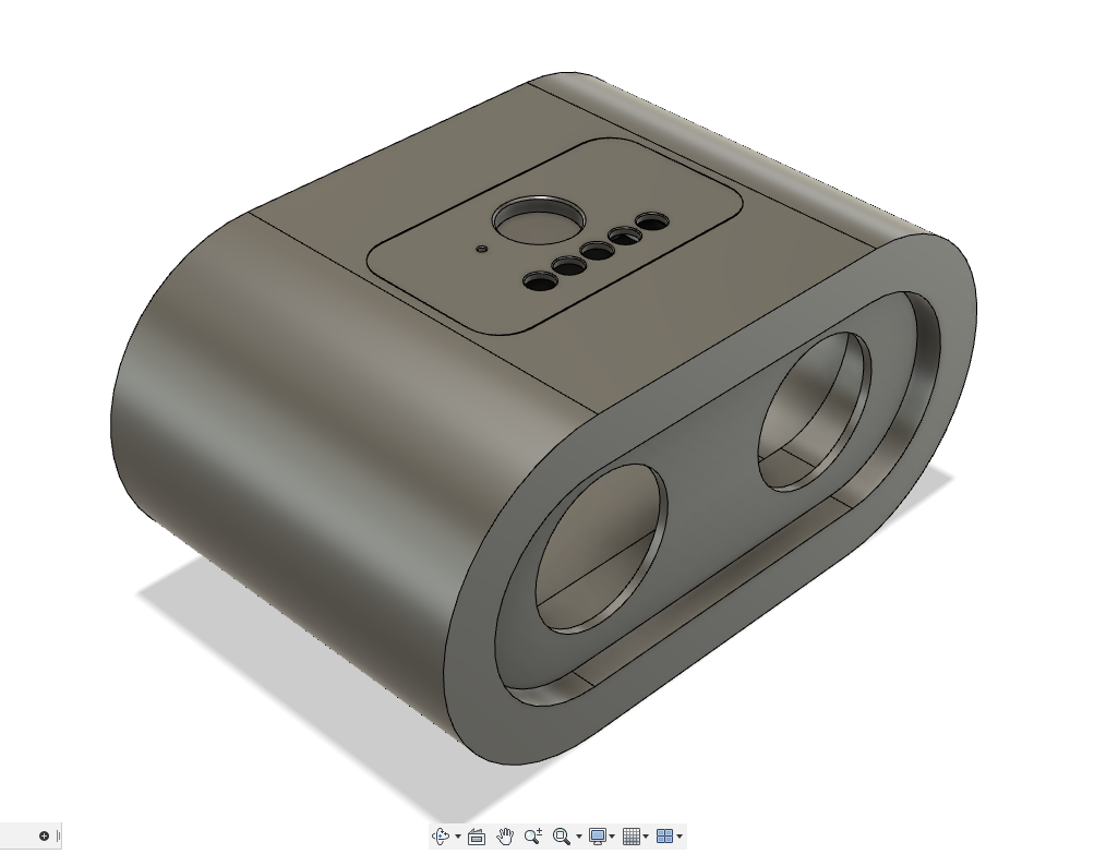
The enclosure was also going to be lot of work and I wanted it to be good. I started from the idea of a vintage bakelite radio but I didn't see how to do that easily. Then I found this (very useful!) video on MDF 'kerfing' and the idea on what it should look like started to form.
I started by drawing the radio in Fusion 360 (which is free for personal use) which allowed me to make the idea I had more specific and to see where the problems would lie. Some iterations were needed because of the limitations of the machines I have available. I designed it so it can be made with a circular saw and a simple hand router, although that didn't prove easy.
Once I was happy with the general look I drew it in detail. First I designed the control panel so it could hold breakout boards containing the necessary electronics. Then I drew the shell with a cutout for the control panel. (There seems to be a slight problem with importing the assembly in Tinkercad, sorry for the faults in the design. The STL should be fine though).
The Enclosure - Part II, Outer Shell and Control Plate Cutout
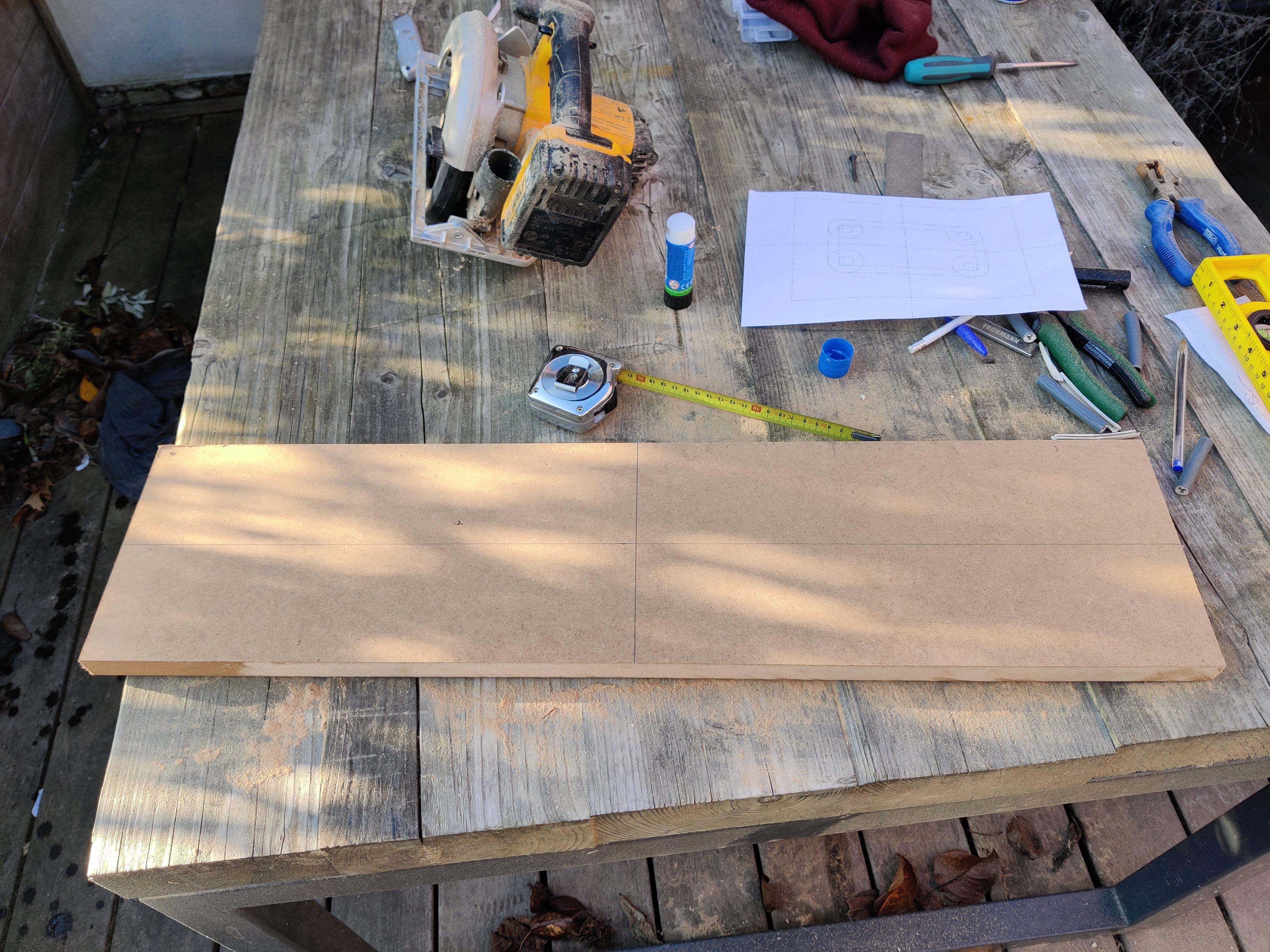
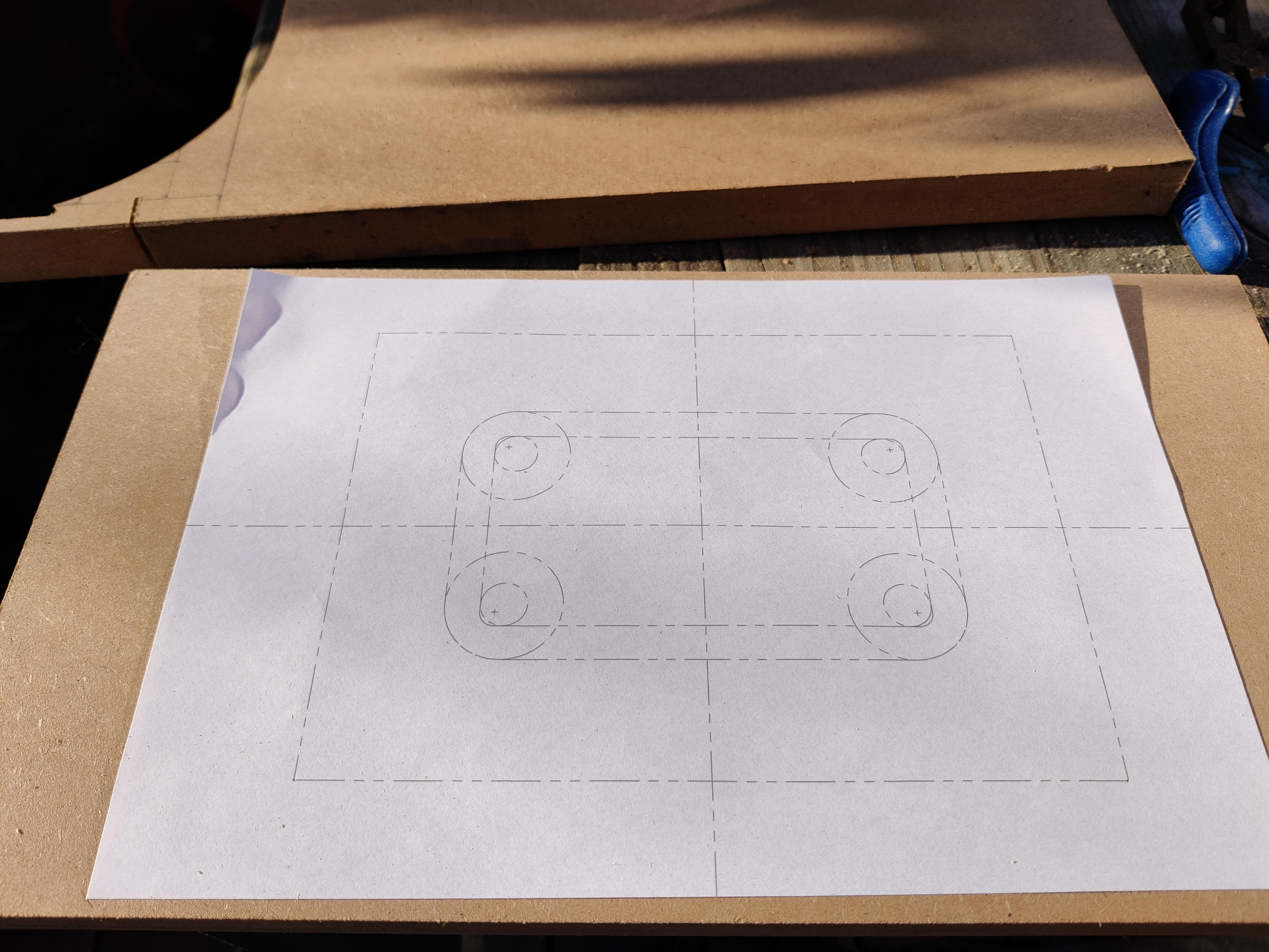
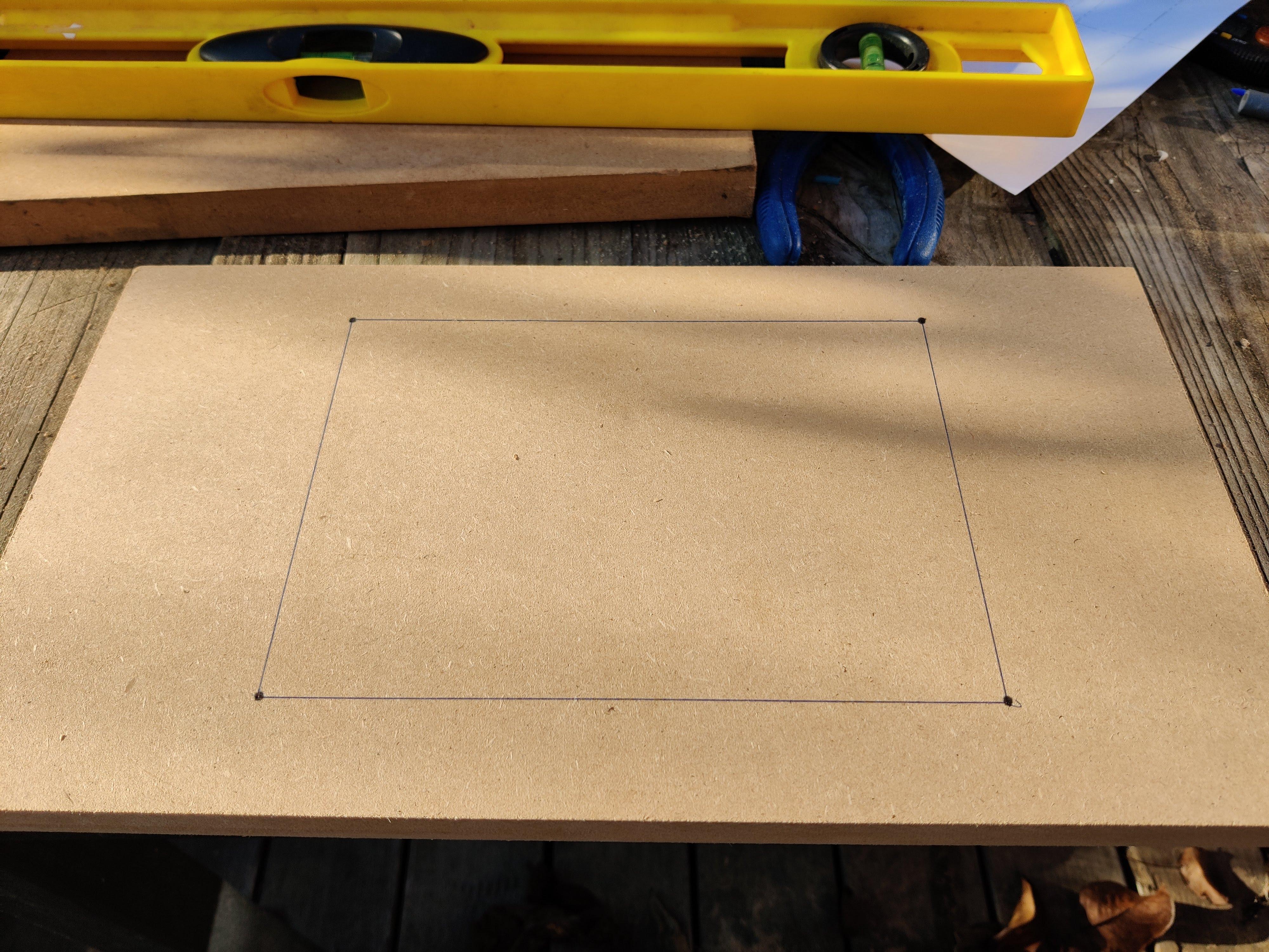
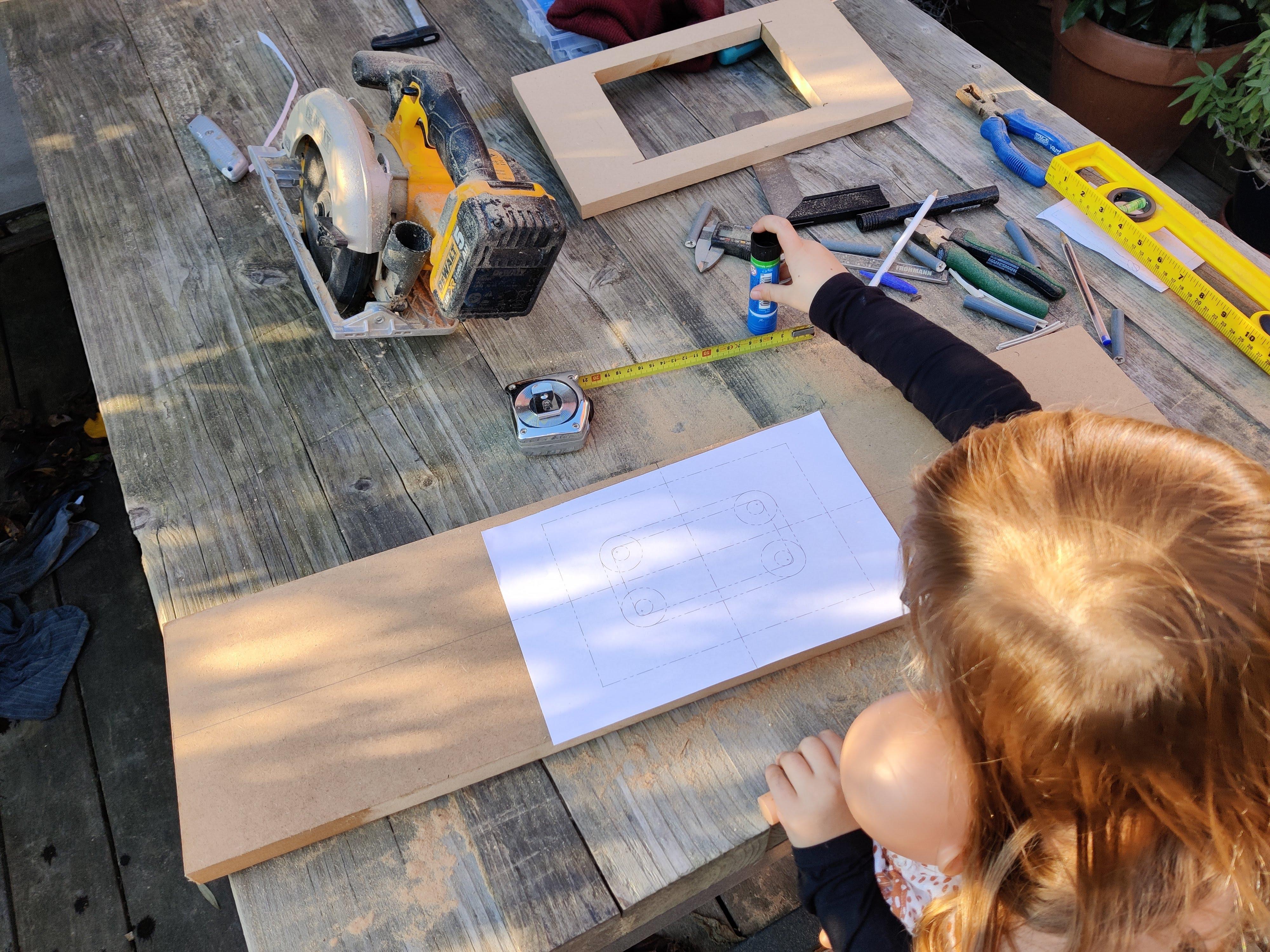
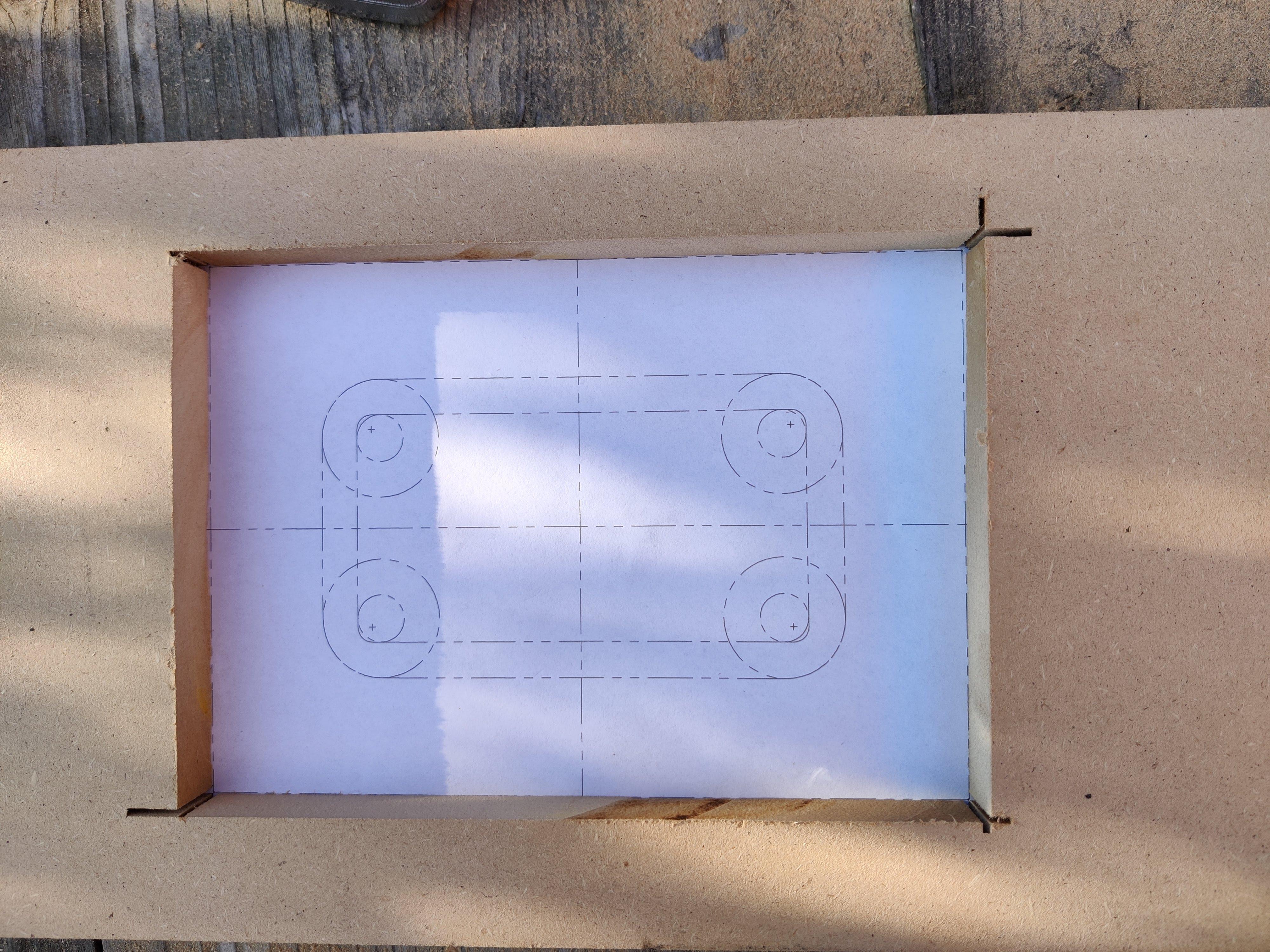
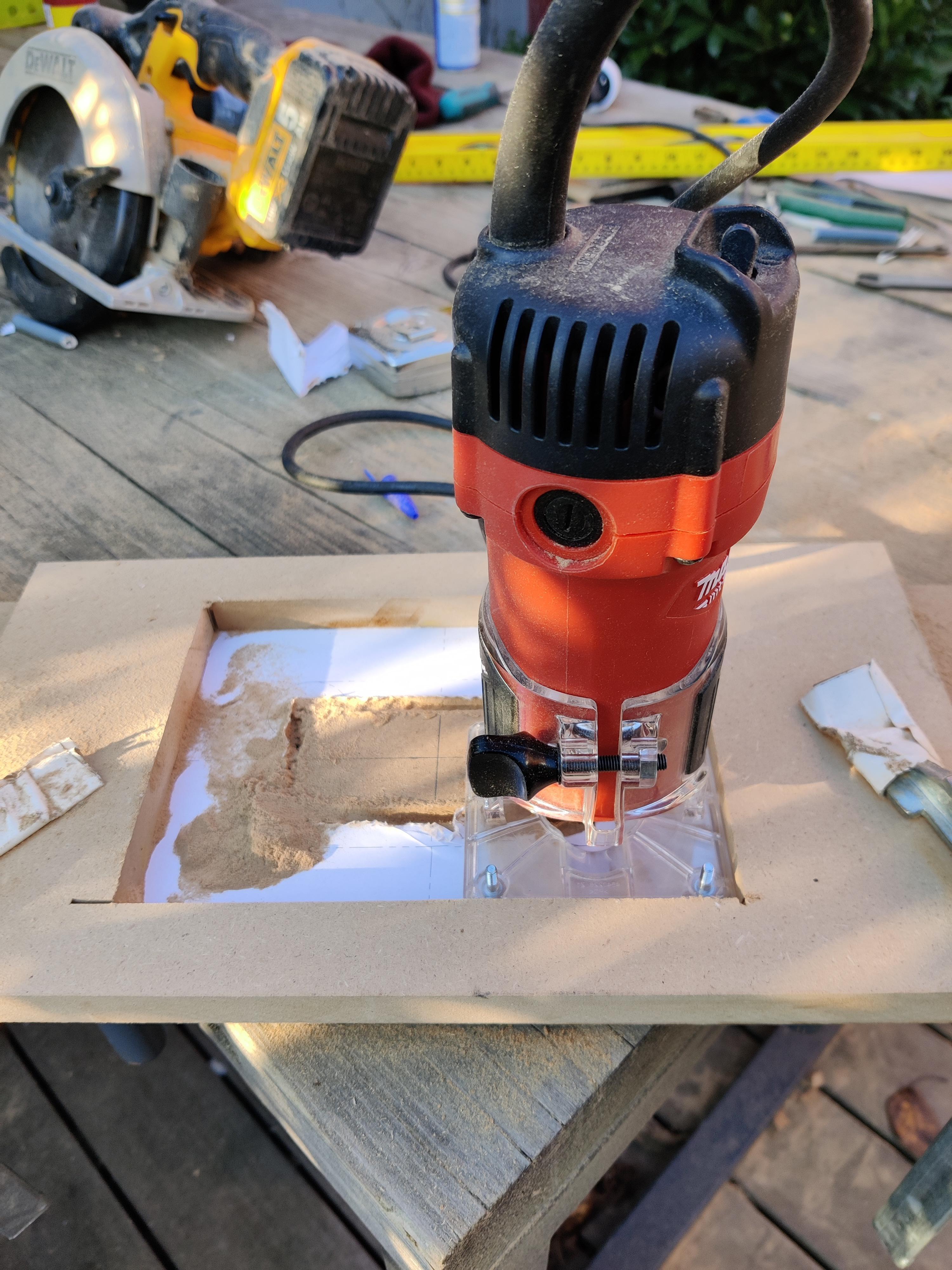
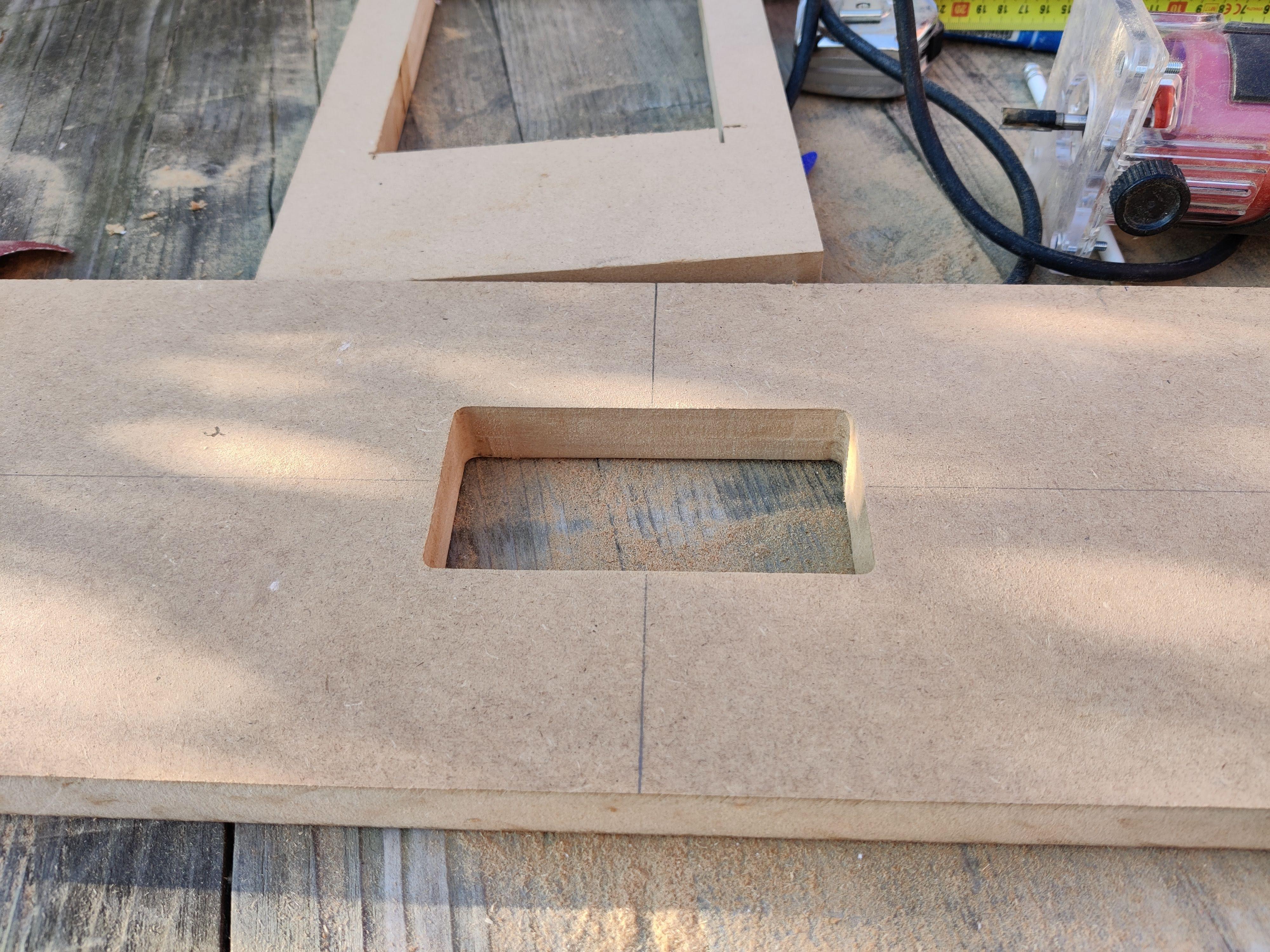
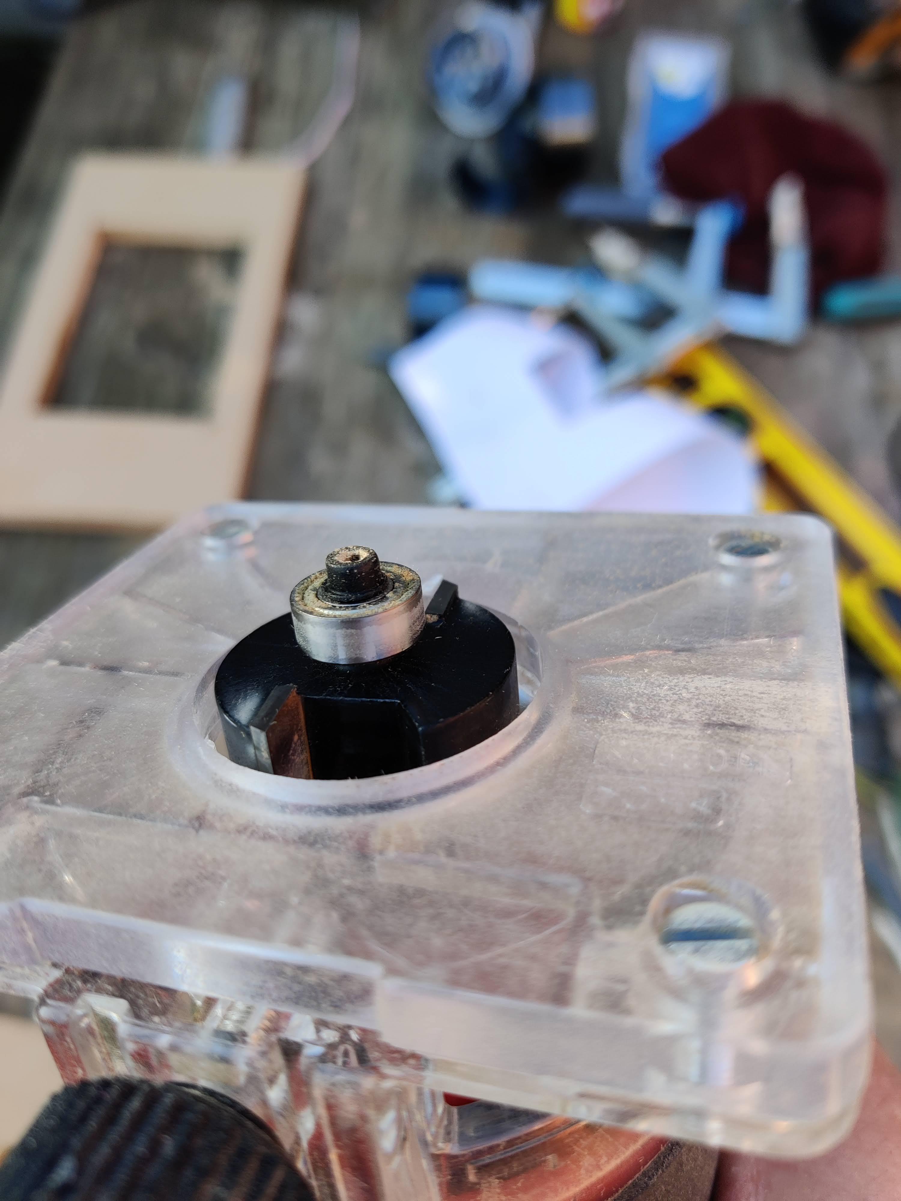
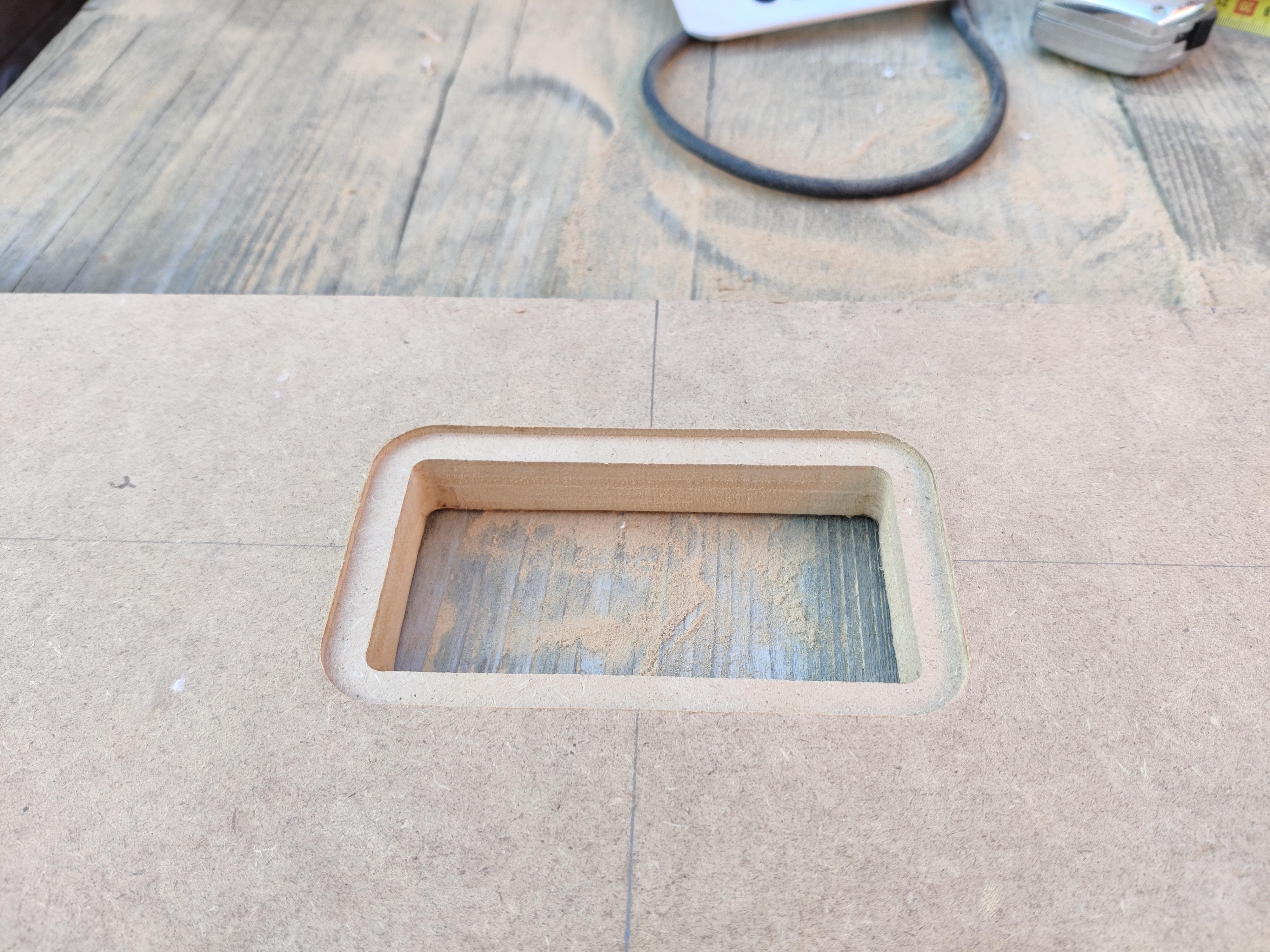
From the finished model I was able to derive the dimensions for the plate I had to cut for the shell and the front and back ribs.
The shell plate length would have to be the total outer circumference of the model. I'd have to cut away enough material so that the remaining material would not be more than the circumference of the inner corners. All the following dimensions could be derived from the fusion model:
- The outer circumference of a 180 degrees corner is 232.5mm
- The inner circumference of a 180 degrees corner is 157.1mm
- This means I have to cut away at least 75.4mm at the inner corner
- This means 38 cuts with a 2mm sawblade equally spaced over 232.5mm
- The total length of the shell should be 232.5 x 2 + 150 x 2 mm = 765mm
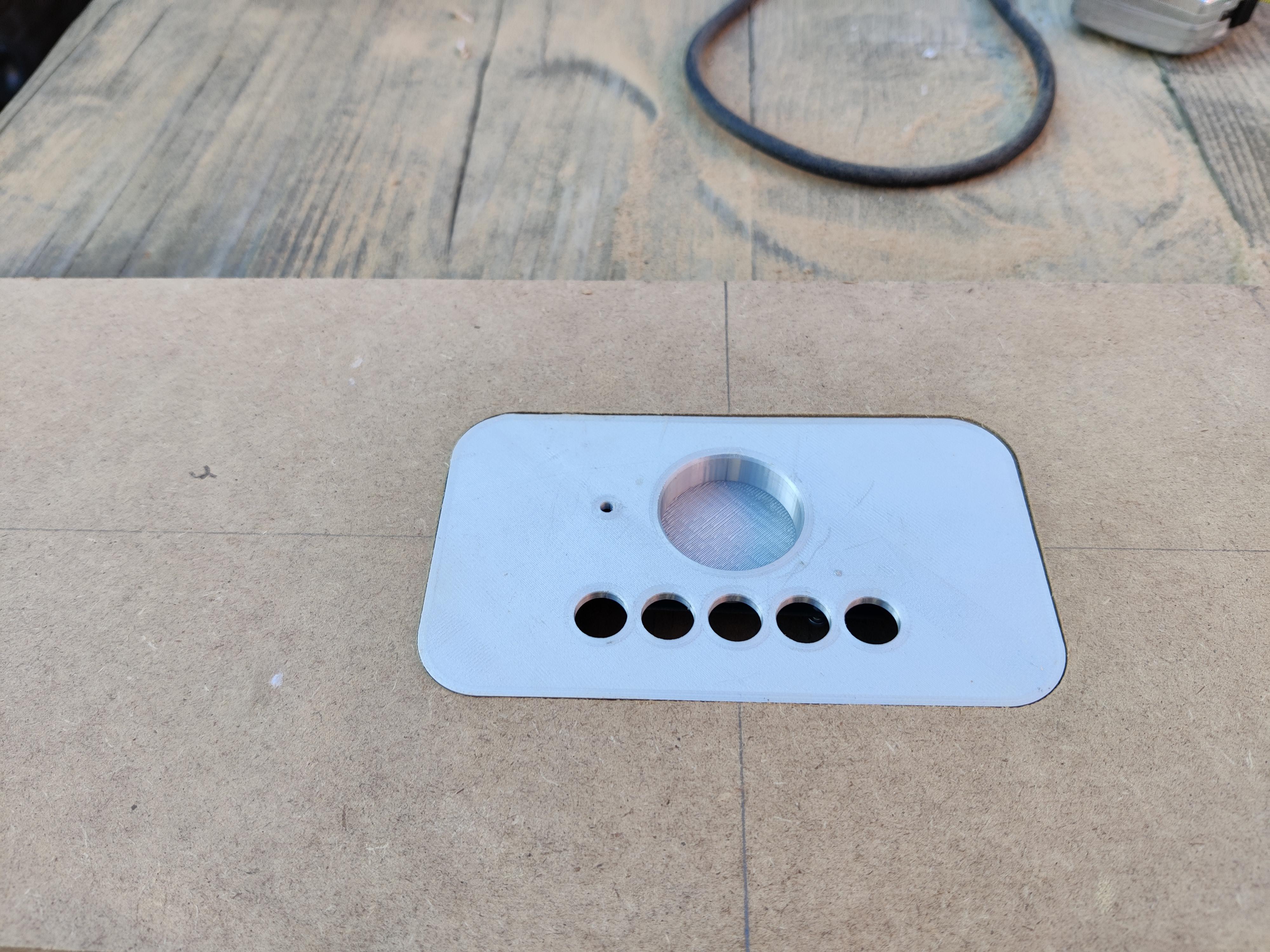
Then I made a template for the cutout for the control plate. This was a lot of thinking and some printing and fitting, and eventually it will only work for my router, but I'll add all files in case you want to use them as guidance anyway.
In the pictures you can see the progress cutting the plate, marking where the cutout would be, making a template for the router while making the cutout, and the bit I used for making the recession for the control plate to sit flush. The cutout turned out to be absolutely perfect from the first try though! Looks like doing the thinking beforehand can sometimes make execution just 'walking the talk'!
Downloads
The Enclosure - Part III, Ribs and Slots
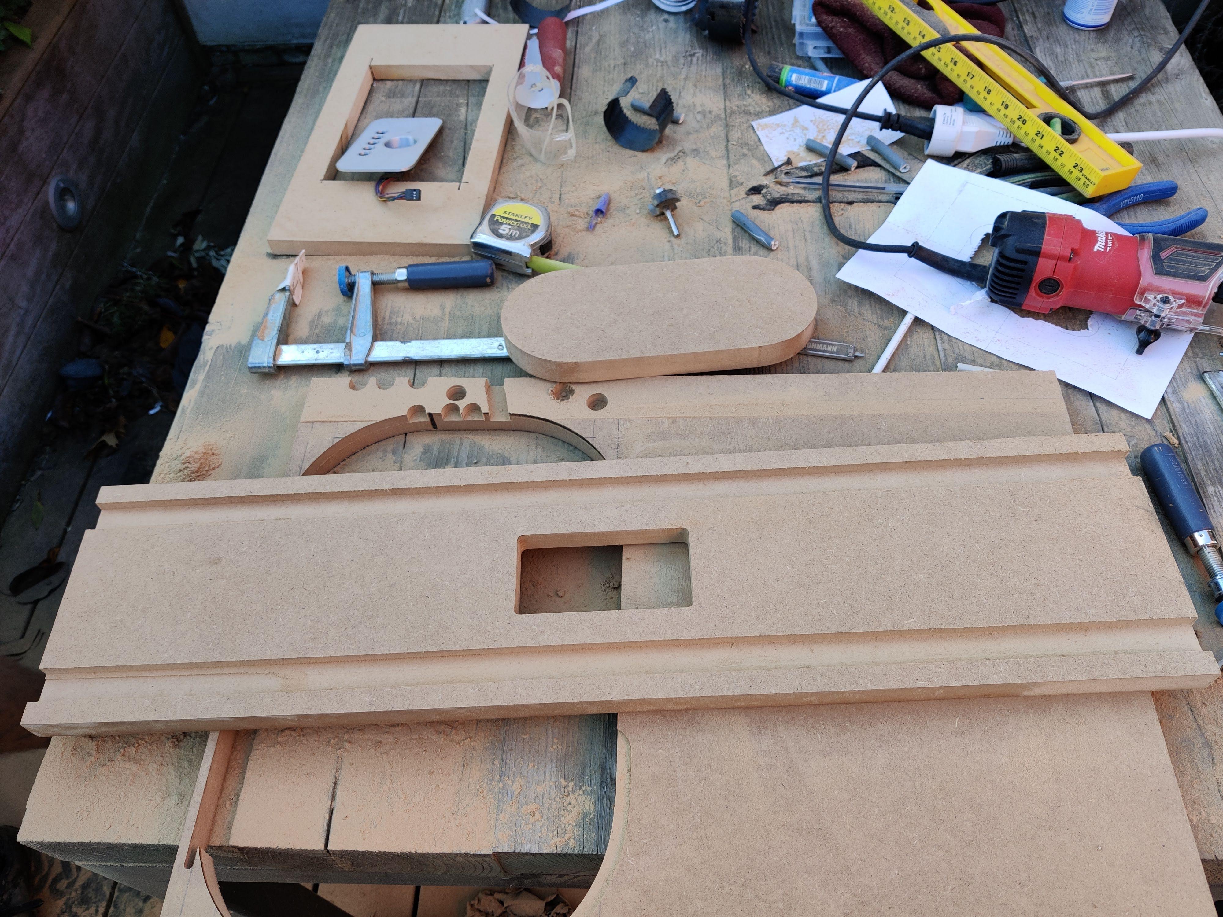
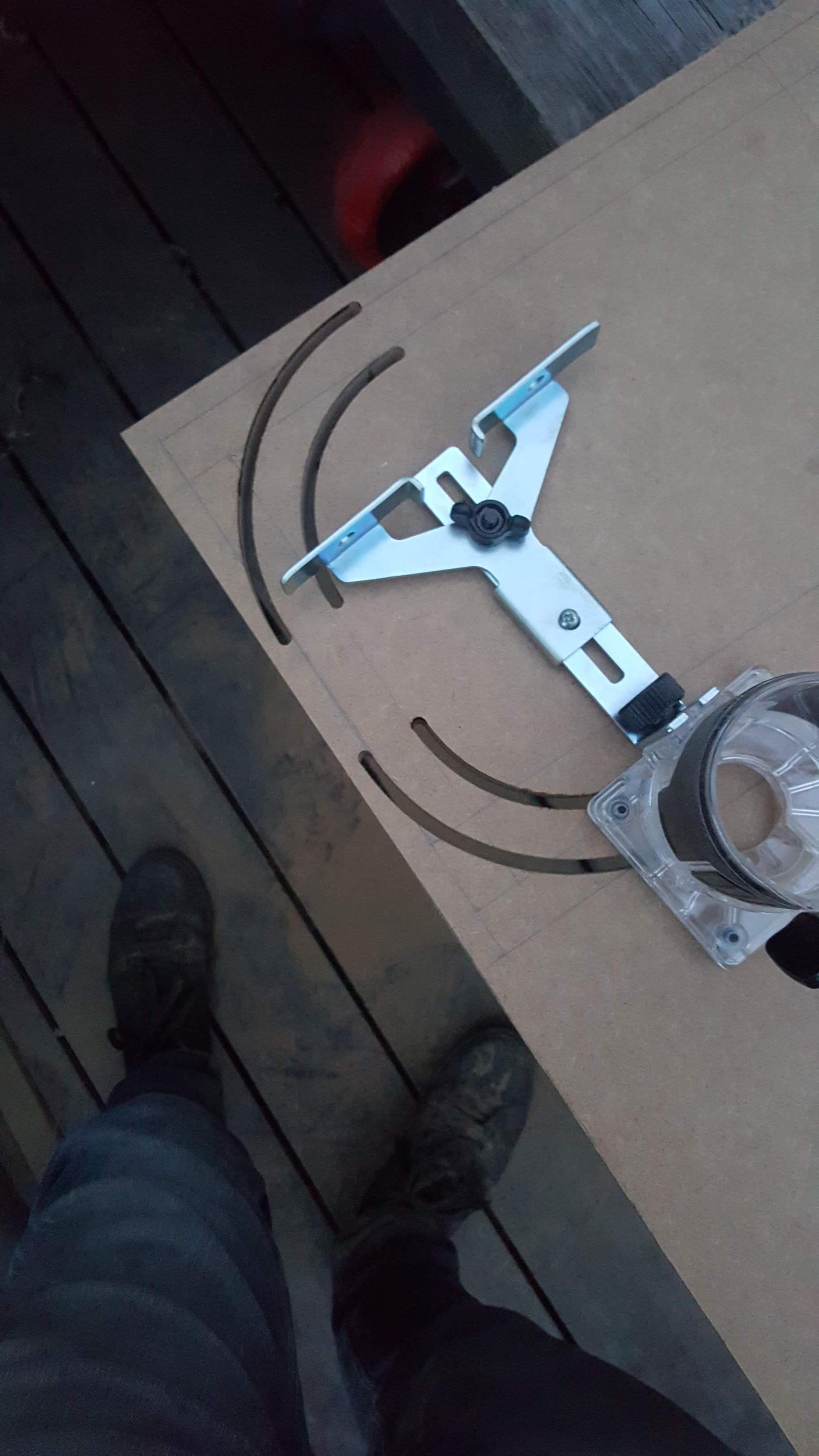
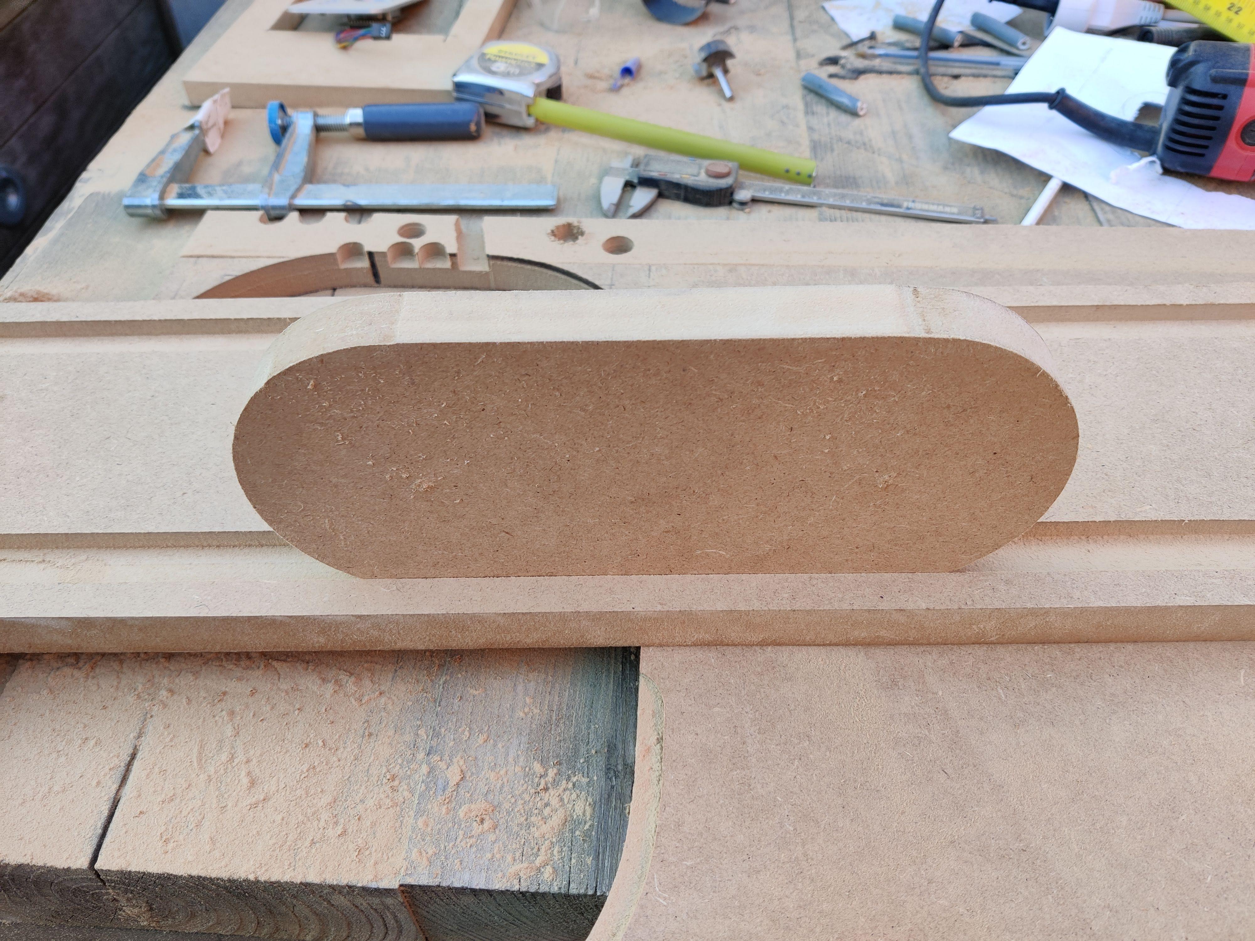
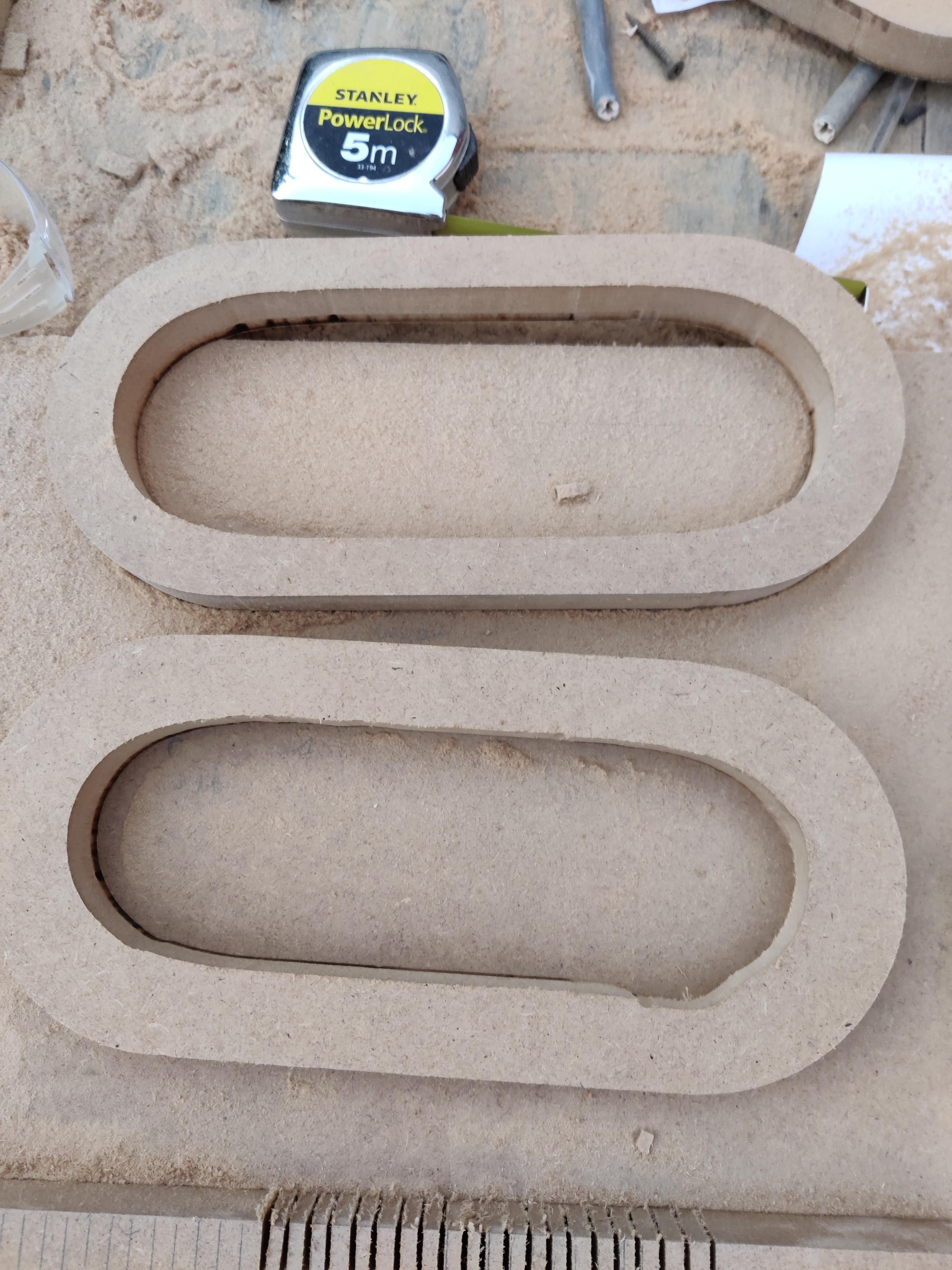
The ribs were cut by making a rectangle first and the rounding the corners with the router and a circular guidance tool. I didn't have a picture of this step but I included one of the tool so you get the idea. I then 'hollowed them out' with a offset tool which was kind of a bad idea, you can see in the pictures that I made some errors because the tool wasn't right for it. This will not matter in the end since there will be a cover plate so you can't see them. The outside of the ribs is the only important shape to bend the shell around.
The Enclosure - Part IV, the Kerfing
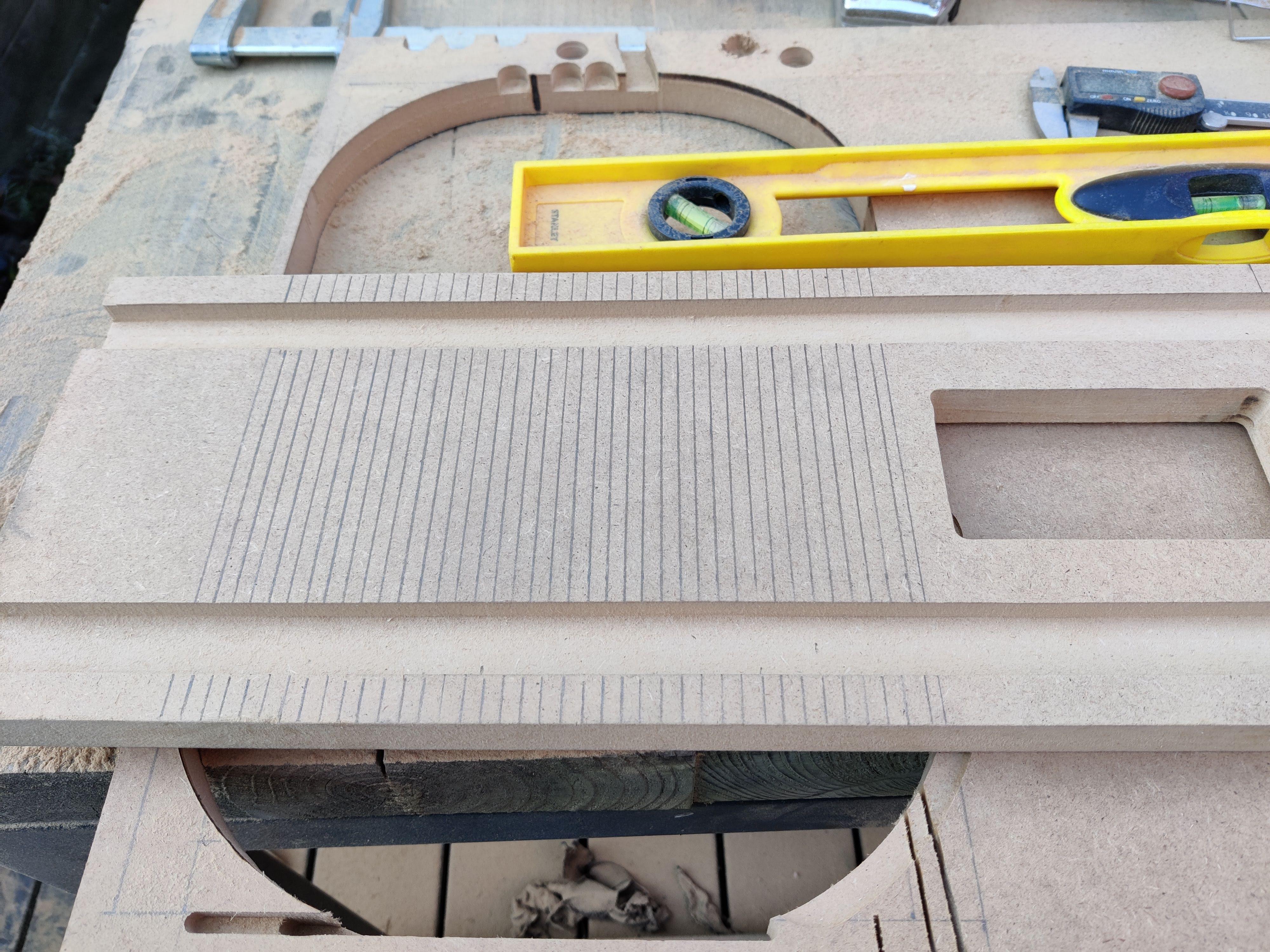
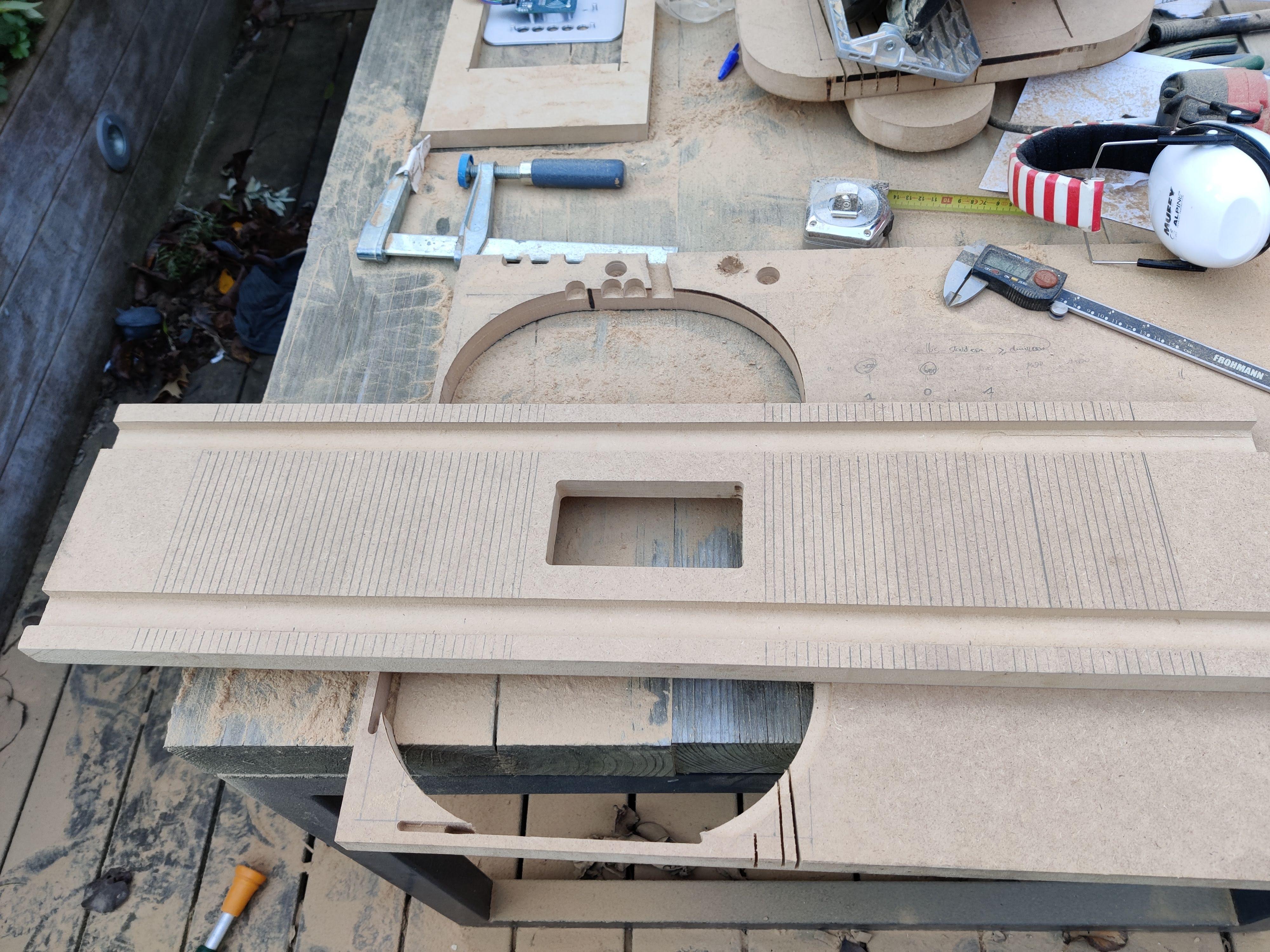
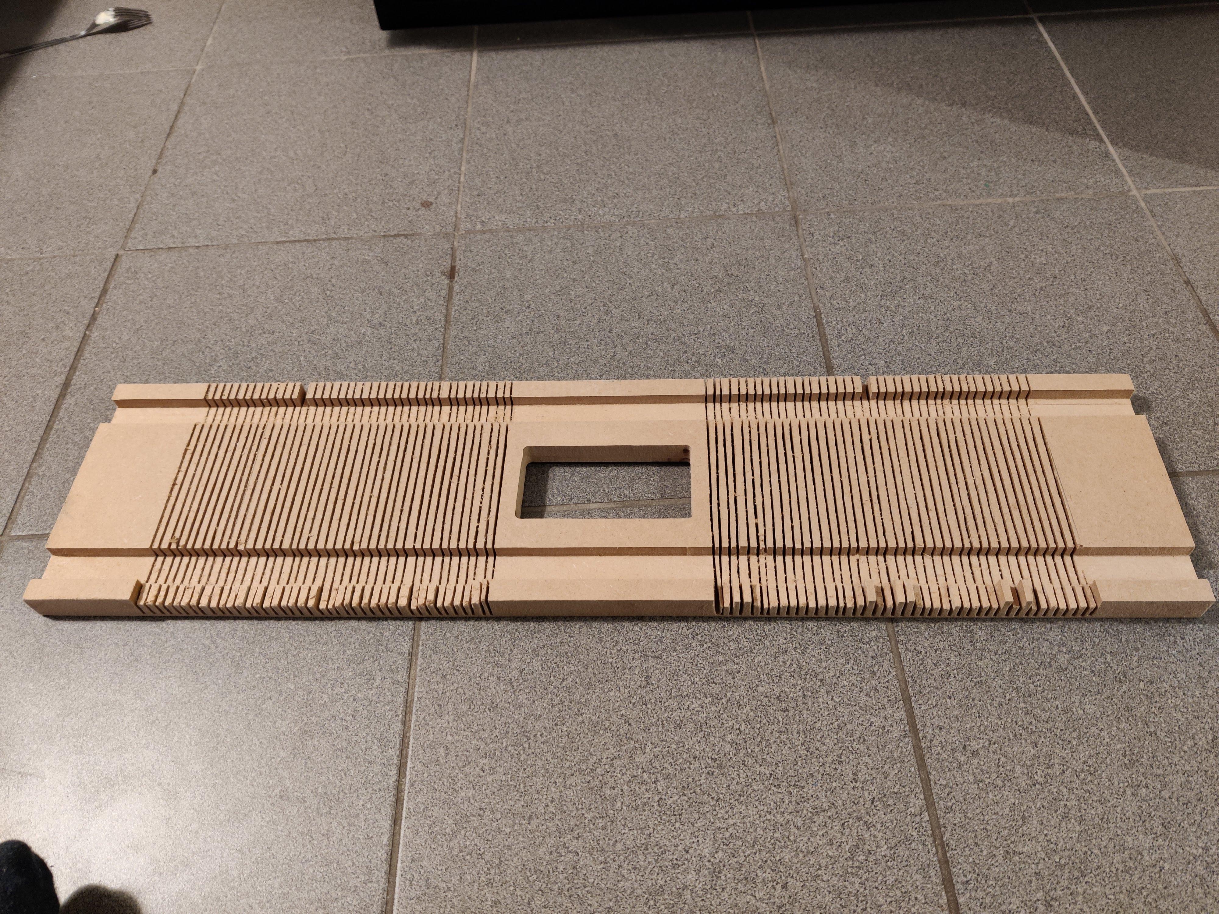
In order to start the kerfing process, I have to measure a lot first and make all the marks for where to cut. I was kind of scared of this step because if I went too deep, I would have ruined all the work I'd already done.
While kerfing the battery of my circular saw was dead every 10-ish cuts so this took a long time. Better borrow a corded saw if I do it again.
Because of the upward motion of the saw at the back of the blade, a lot of the teeth at one side broke off. This was a bummer but I figured I could fix it with a lot of MDF filler.
The Enclosure - Part V, Assembly
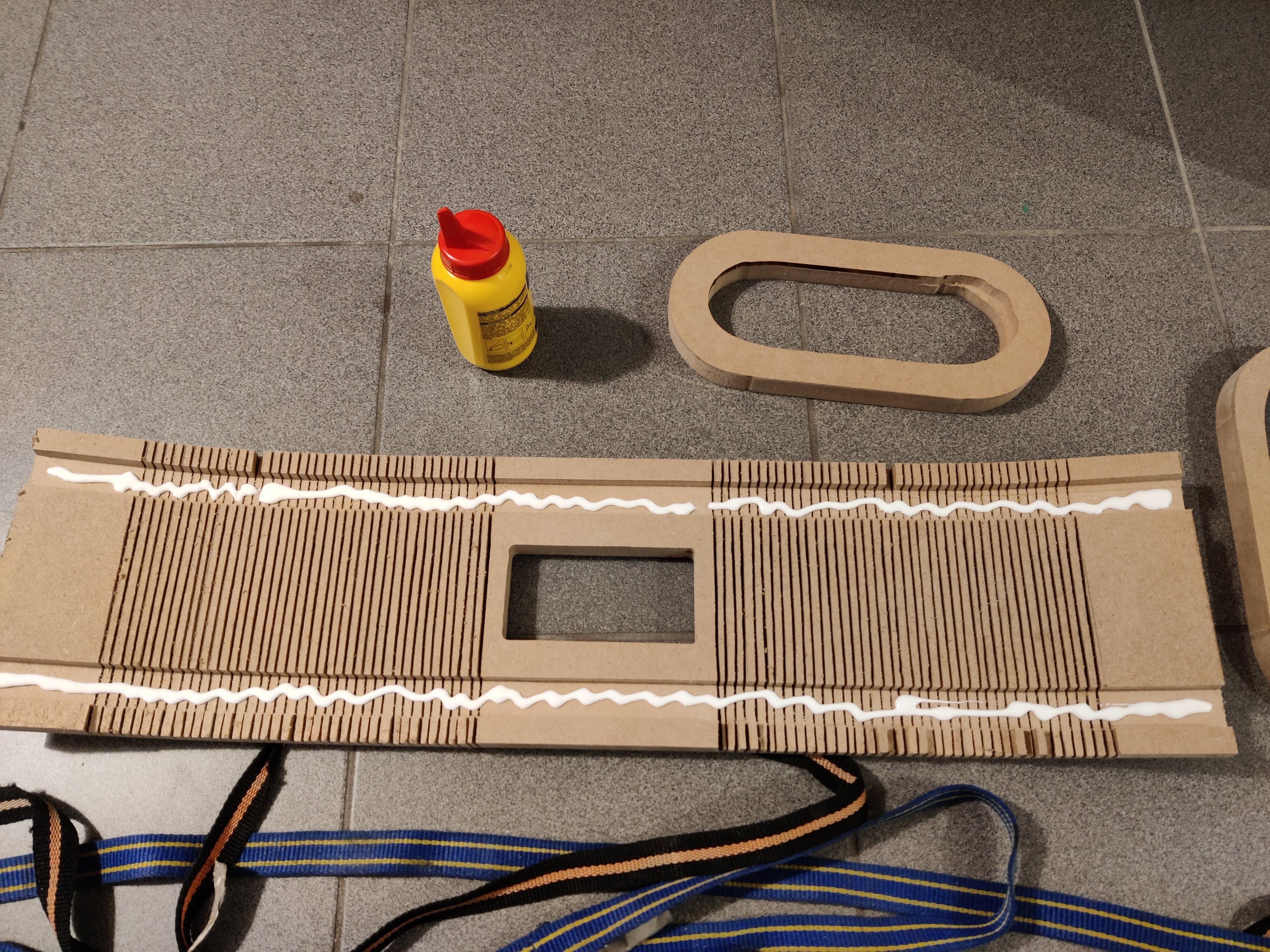
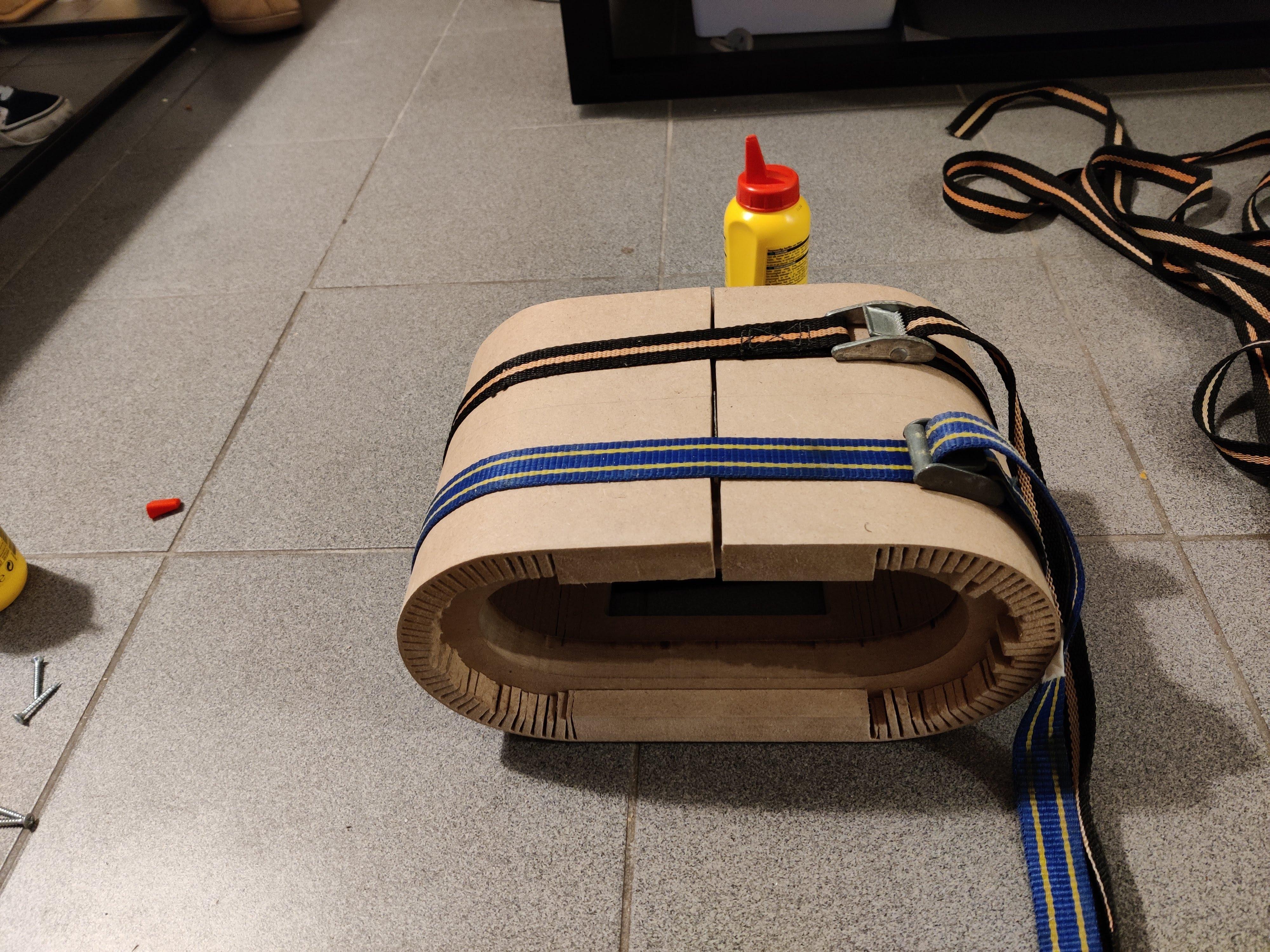
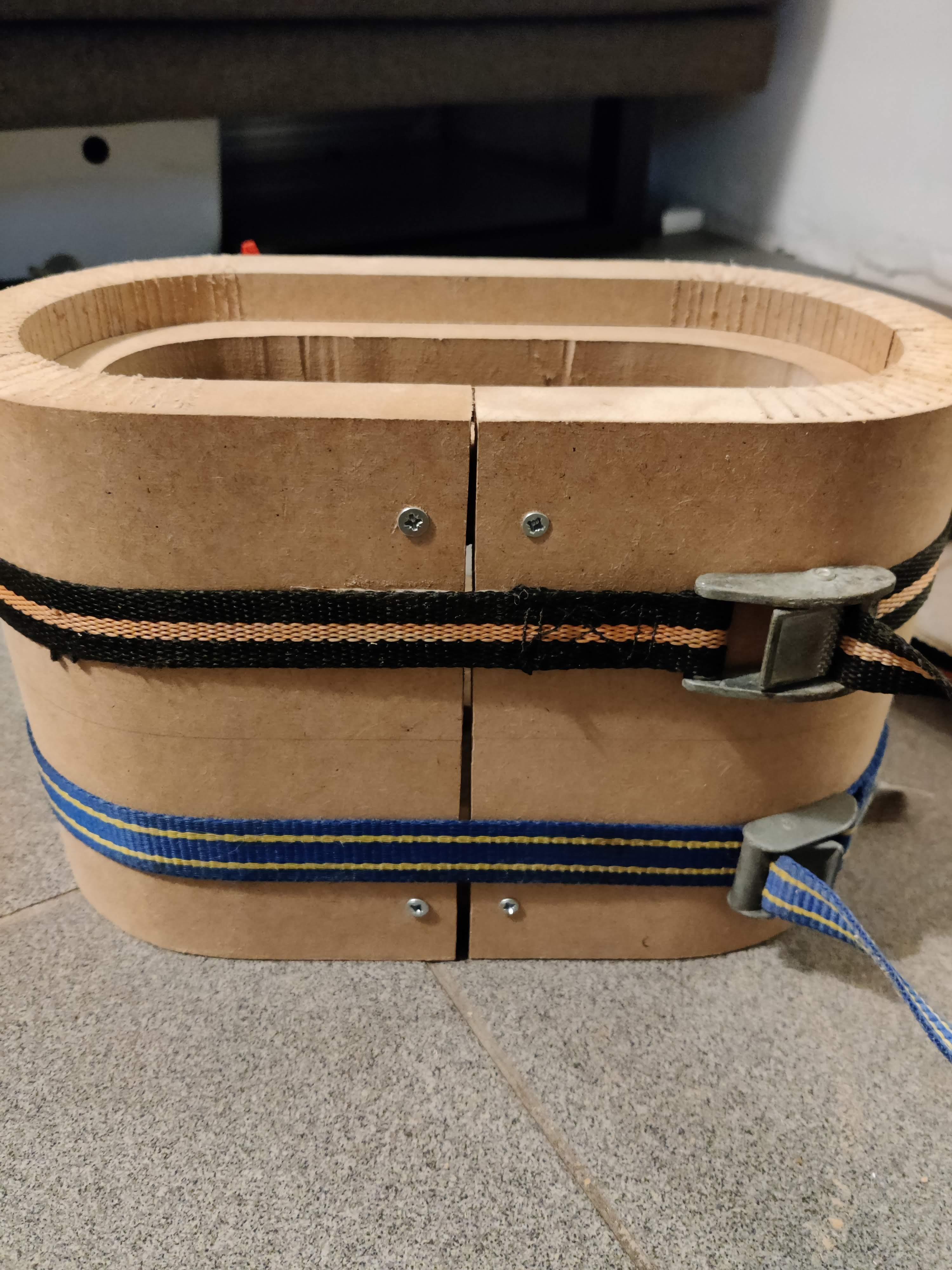
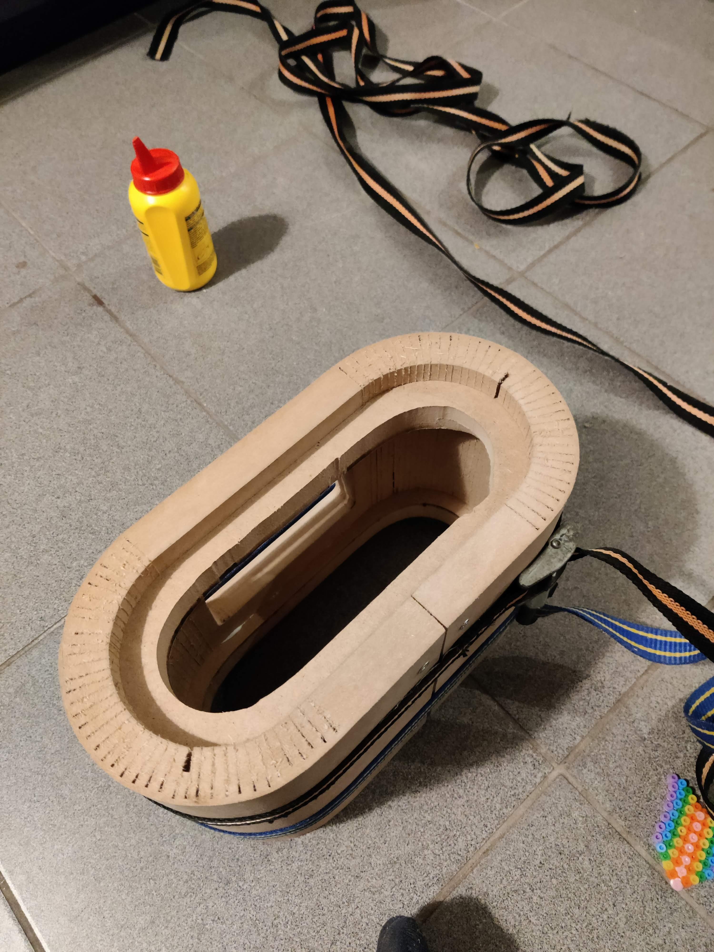
An exciting step! It seemed immediately after kerfing that I had done everything right. Except for the fact that the shell turned out to be a little too large, but I figured this was easlily fixable...
I made them overlap at the bottom, drew a line where to cut so they would fit perfectly, and after cutting they were too short, which resulted in a gap. It was late by then but I figured I'd fill this with MDF filler anyway.
Then I had to glue the shell to the ribs, carefully bending it and squeezing everything together with straps so the glue could dry nicely. I added screws at the ends to be sure the shell would never loosen by itself again.
The Enclosure - Part VI, MDF Filler and Paint
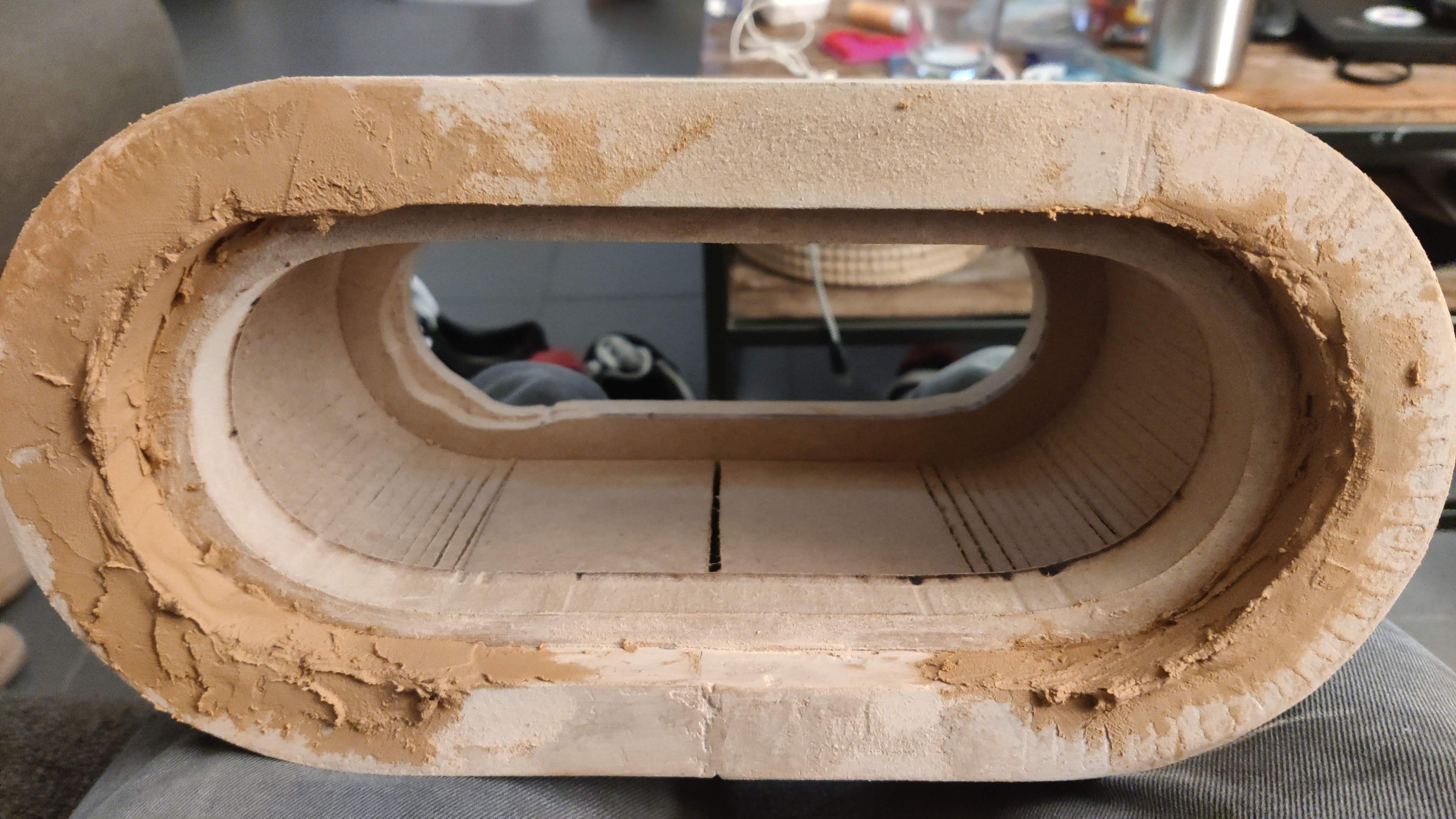
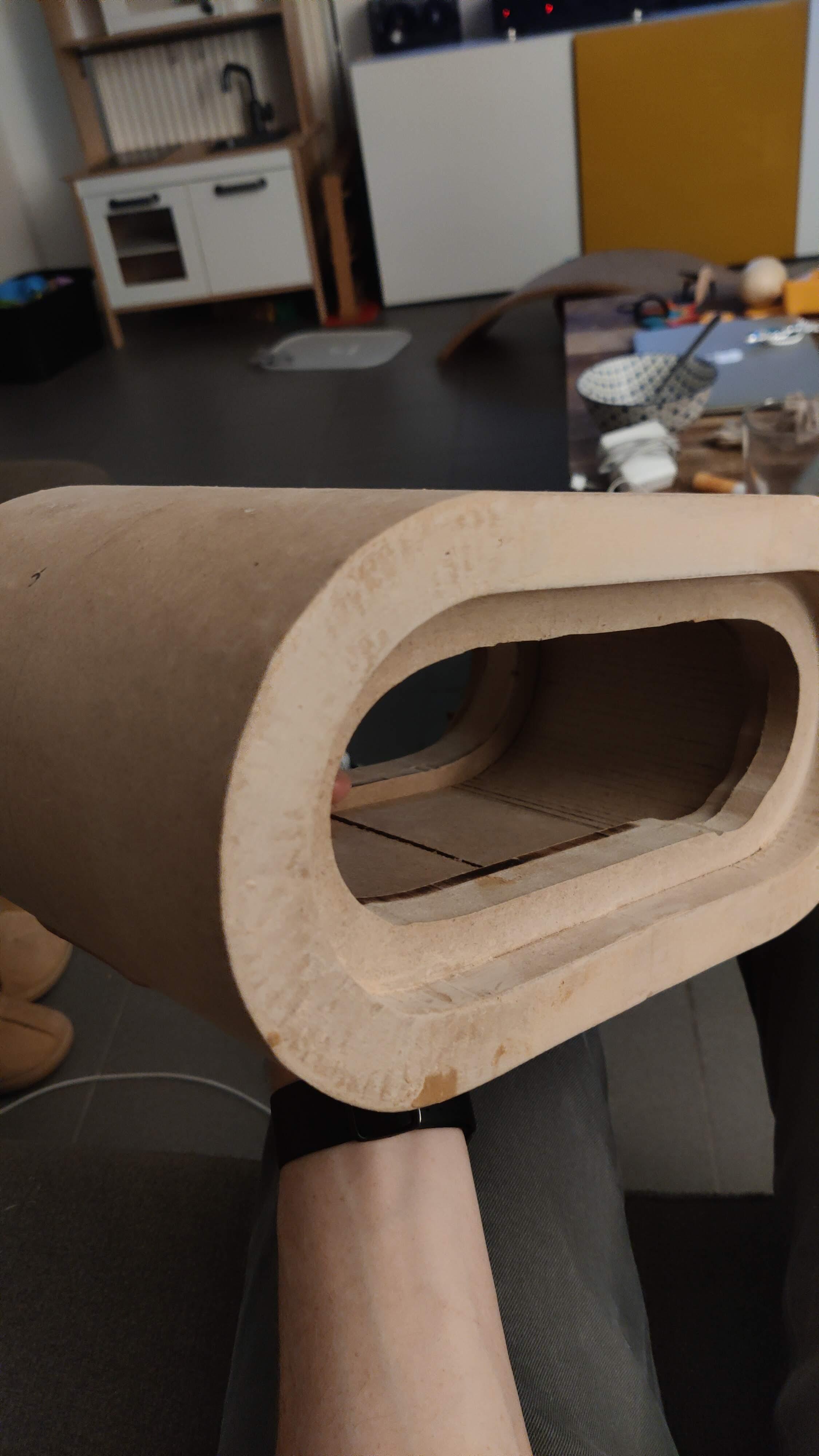
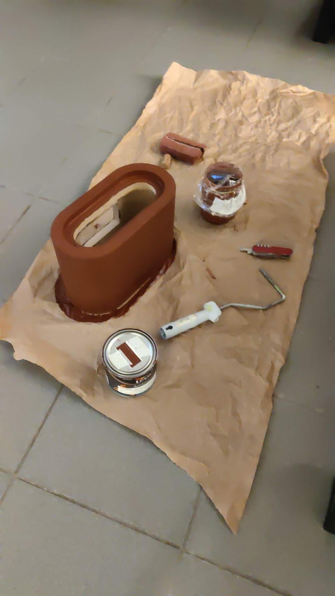
You saw in the previous step which state it was in after assemble. The missing 'teeth' and the gap would have to be filled up in order for the result to look clean and smooth.
This happened in a lot of different iterations. Filling the gaps generously with the filler, letting it dry and then cutting away pieces and sanding everything like a true sculptor. I really took my time, it took me maybe a week in total because of the drying time. But I'm very happy with the result.
After the shape was to my liking, it was time for a final sanding and then 5 layers of paint with sanding between layers. Again more than a week because the paint took long to dry fully, especially after a few layers.
The Enclosure - Part VII, the Speaker Plate
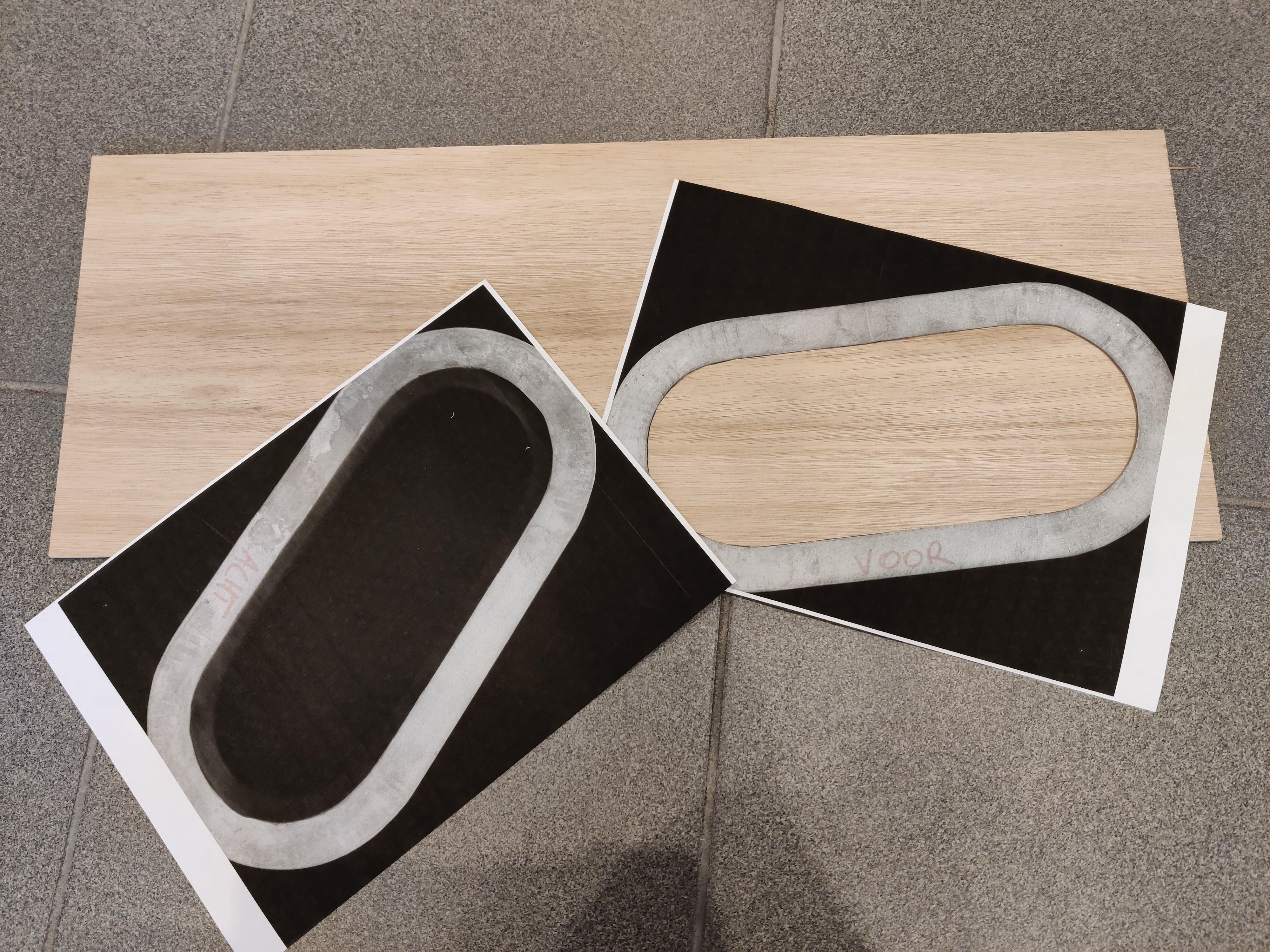
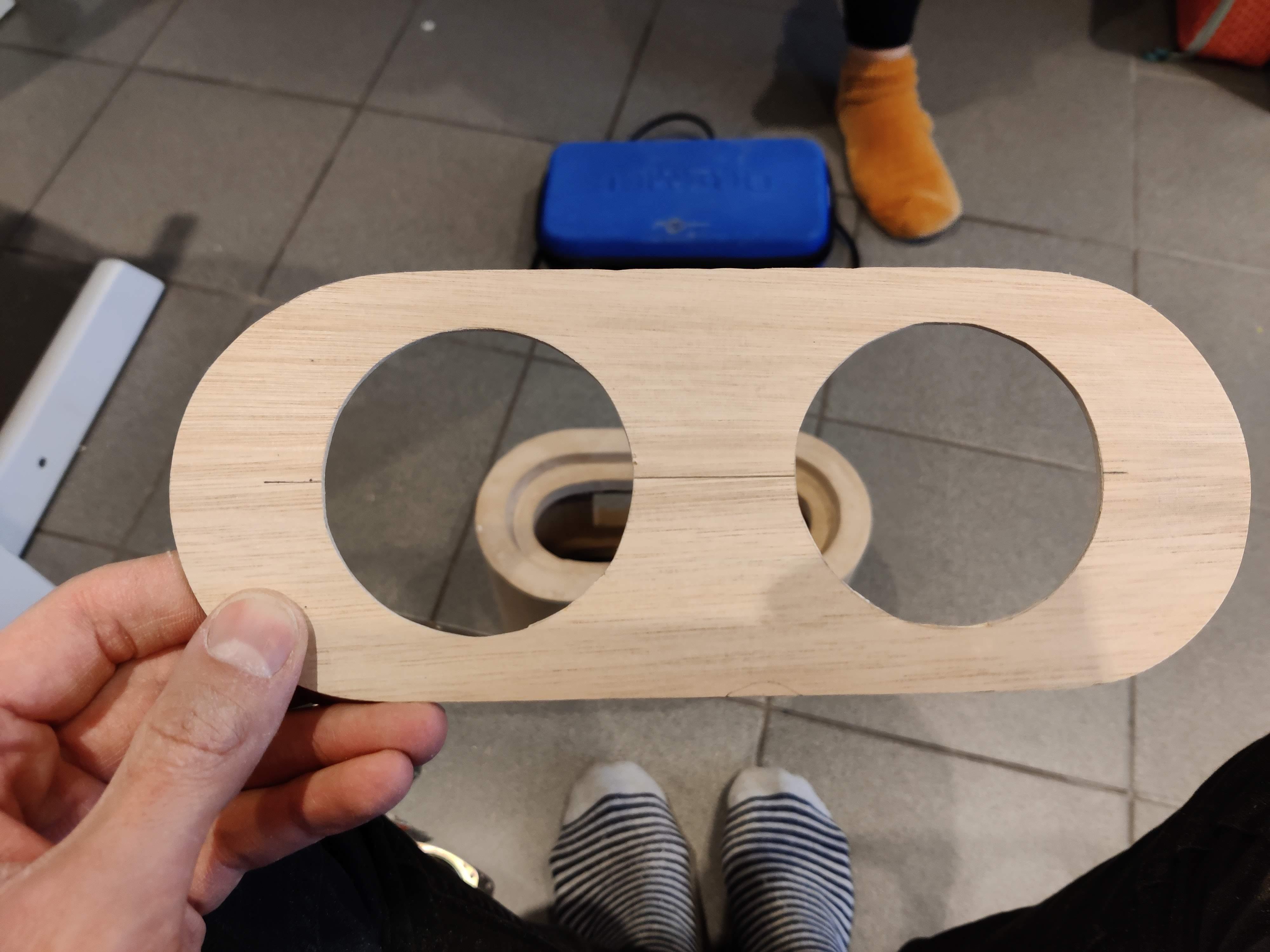
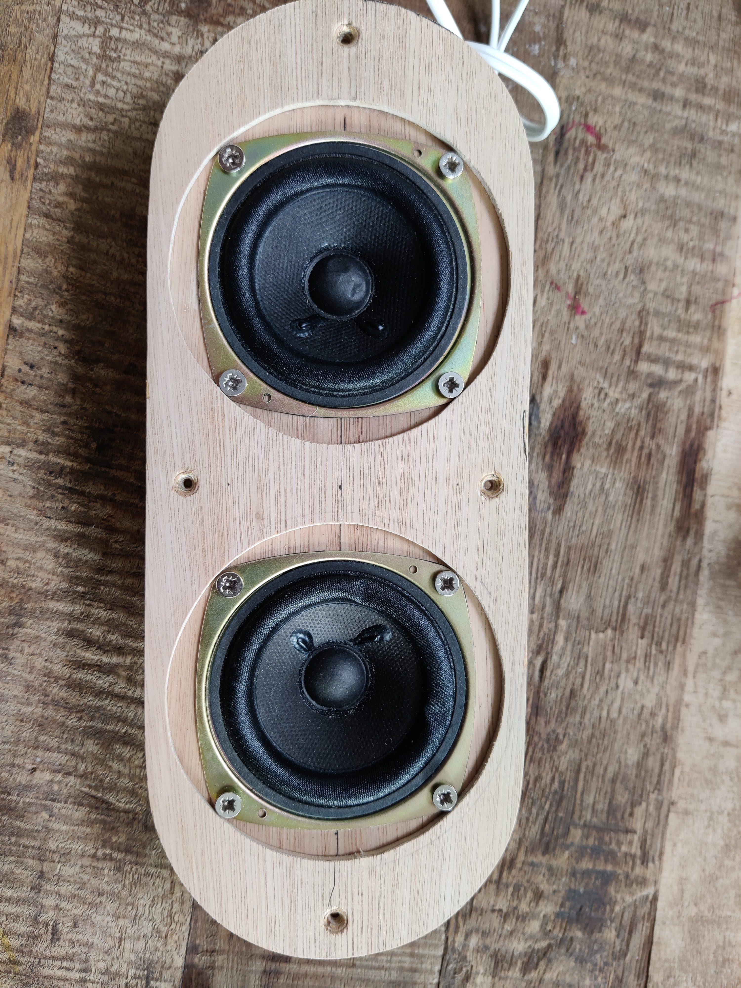
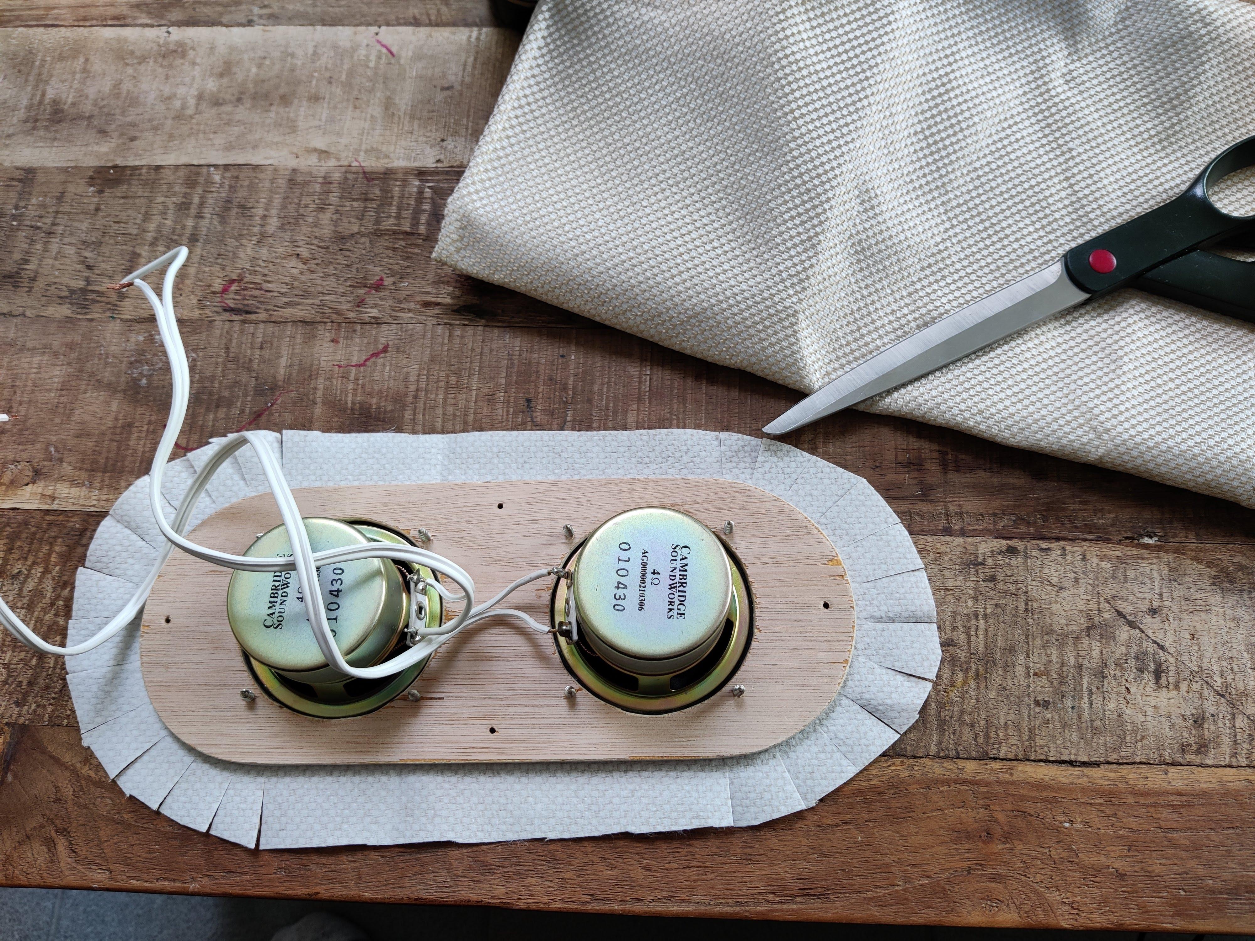
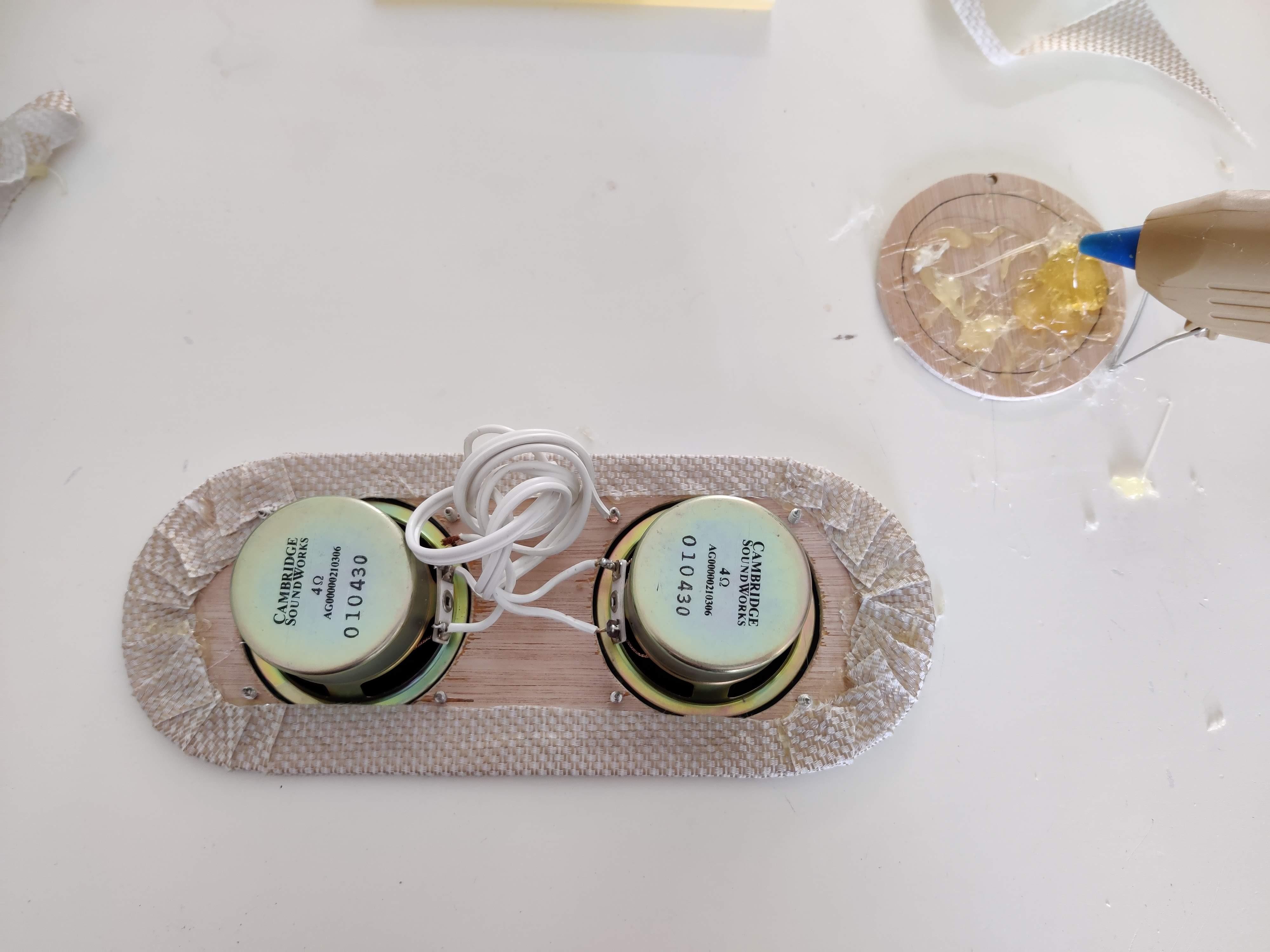
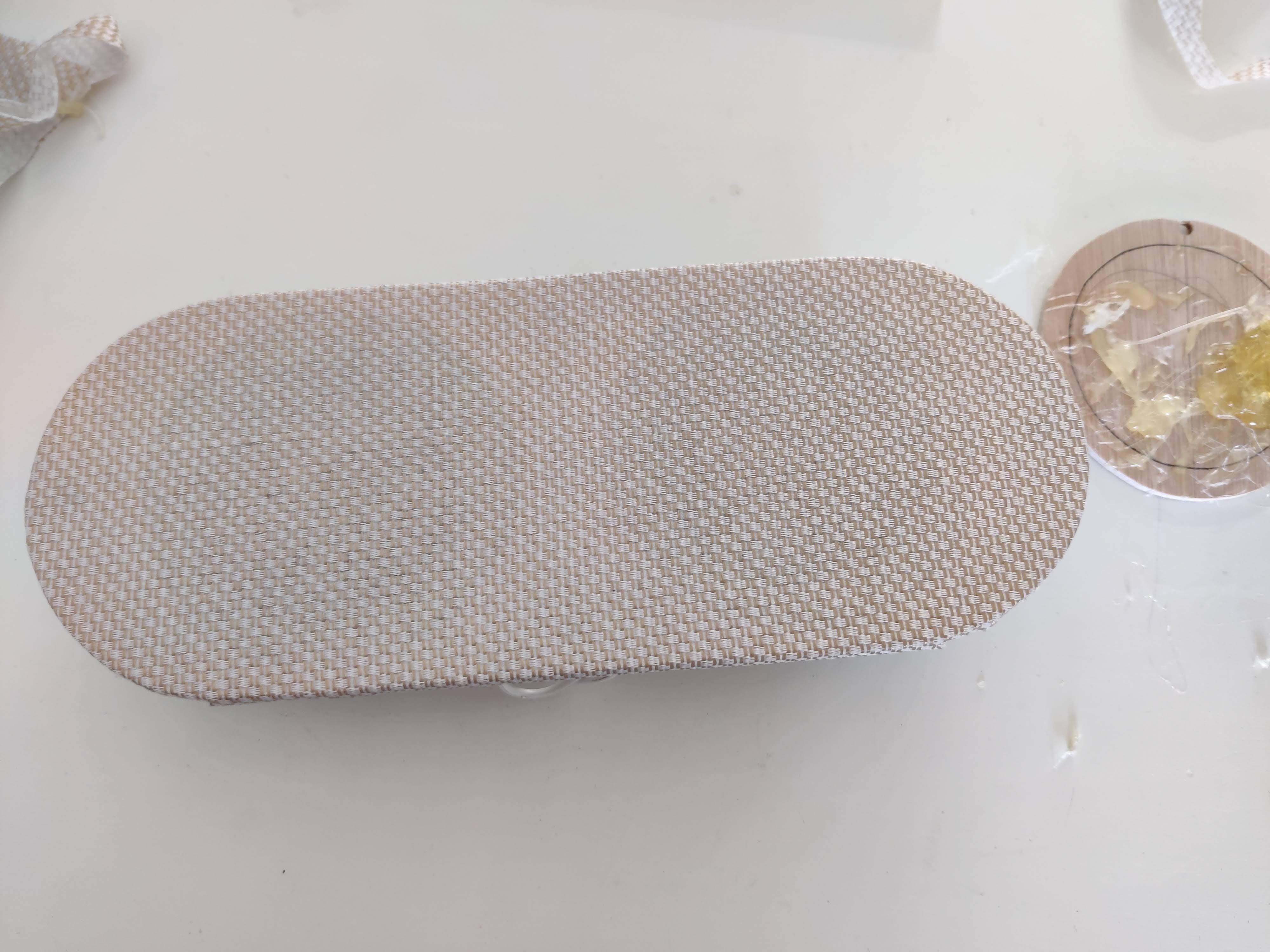
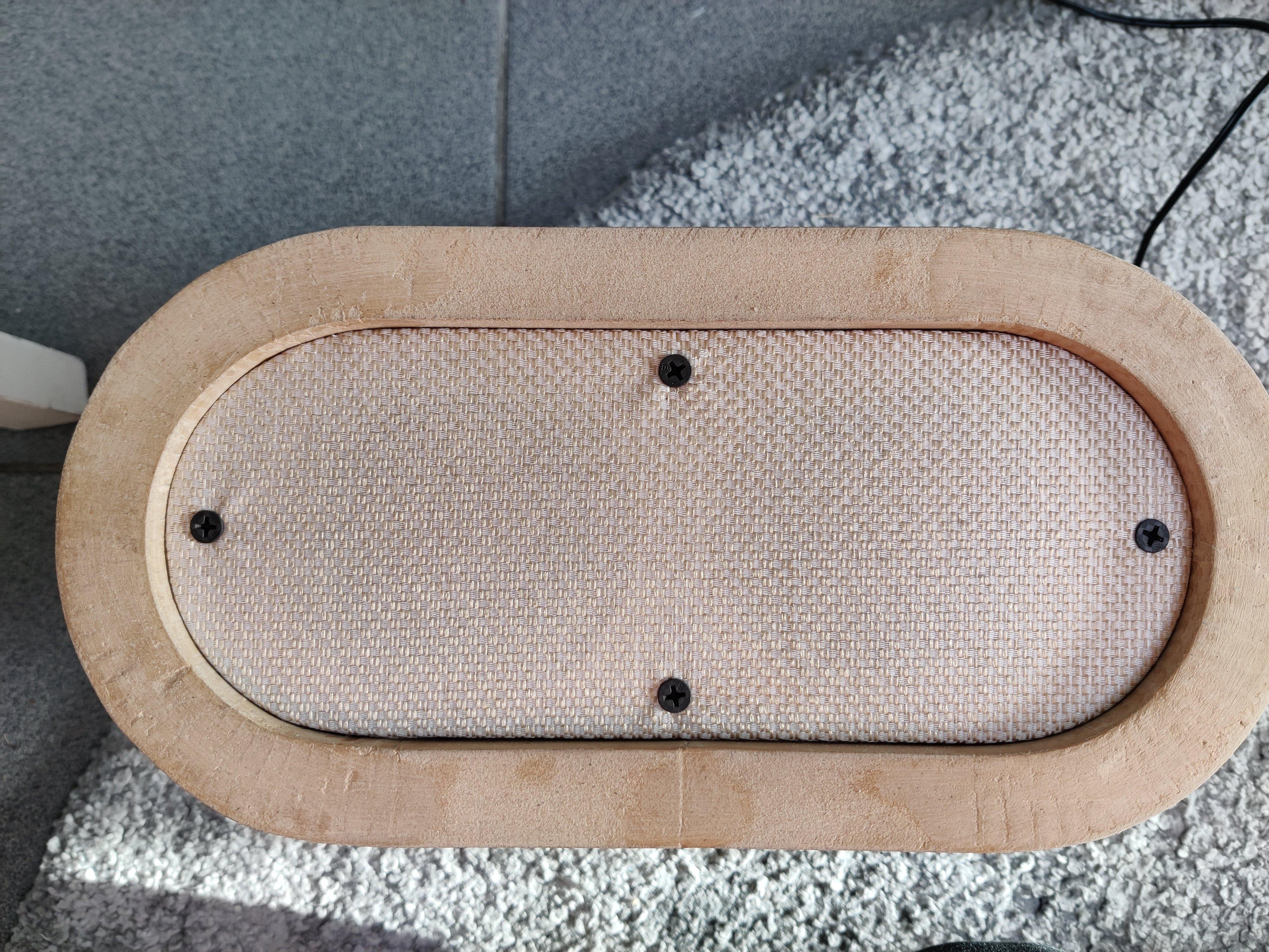
For the speaker plate, I put the whole thing in a scanner in order to be able to cut pieces of wooden plate to the exact shape. I wasn't sure the front would be exactly as designed in Fusion 360 because I made it by hand and after all the scultping of the MDF filler, so I thought this was the best way to make exactly the right shape. I've been sanding to make it fit after all so perhaps this was an unnecessary extra step.
I cut two plates and glued them together because this was scrap wood I had lying around. I could have used thicker MDF and made a recession for the speaker as with the control plate too.
The fabric is specific speaker fabric I bought for the restoration of a vintage radio once, of which I had a lot left over.
The pictures speak for themselves I think. This step actually happened somewhere between the MDF filler scuplting and the painting. The idea for the back cover is exactly the same but instead of speakers, there will be a hole for the cable. Possibly I'll add another barrel jack connection later.
The Enclosure - Part VIII, Raspberry Pi Mount
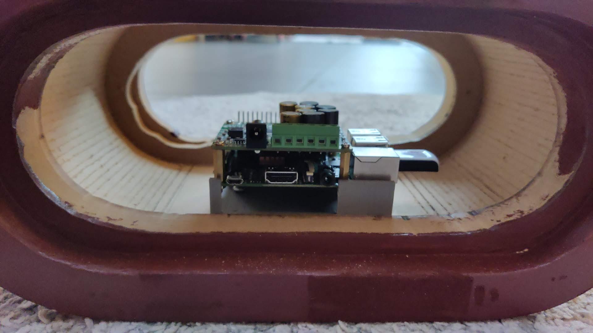
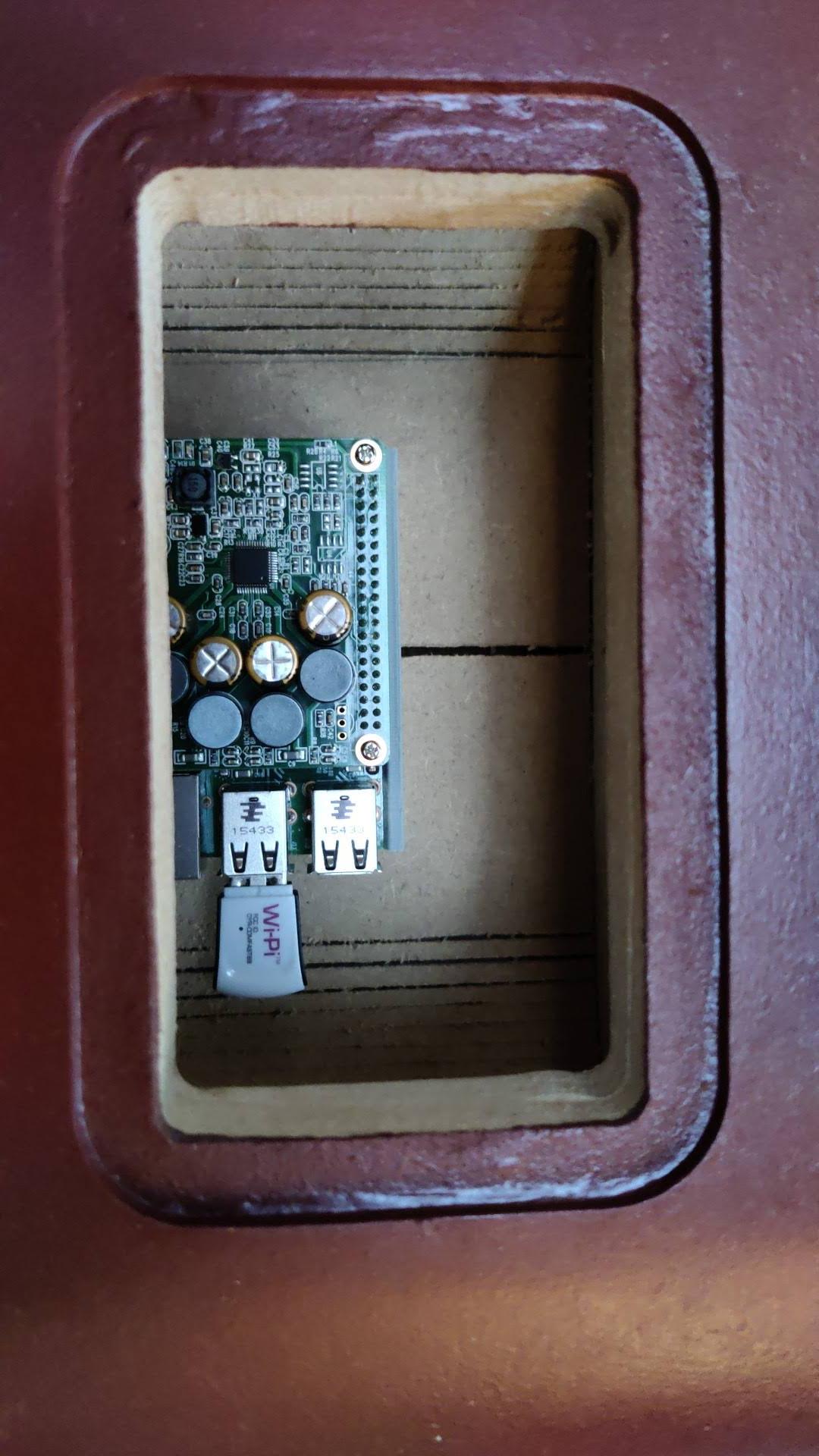
One thing I had postponed as long as possible was the mounting of the Raspberry Pi. I had been looking at threaded inserts for wood to screw the standoffs directly in, but couldn't find them. I'd thought about making a mounting plate to which I could bolt the Pi. I even thought about just gluing it in with hot glue, but that gave me a very unpleasant feeling.
In the end I came up with a clamp so the pi sits a little elevated so I can reach the SD-card easily, the power and speaker terminals are reachable, and the Pi as a whole is easily removable.
The Enclosure - Part IX, Completion
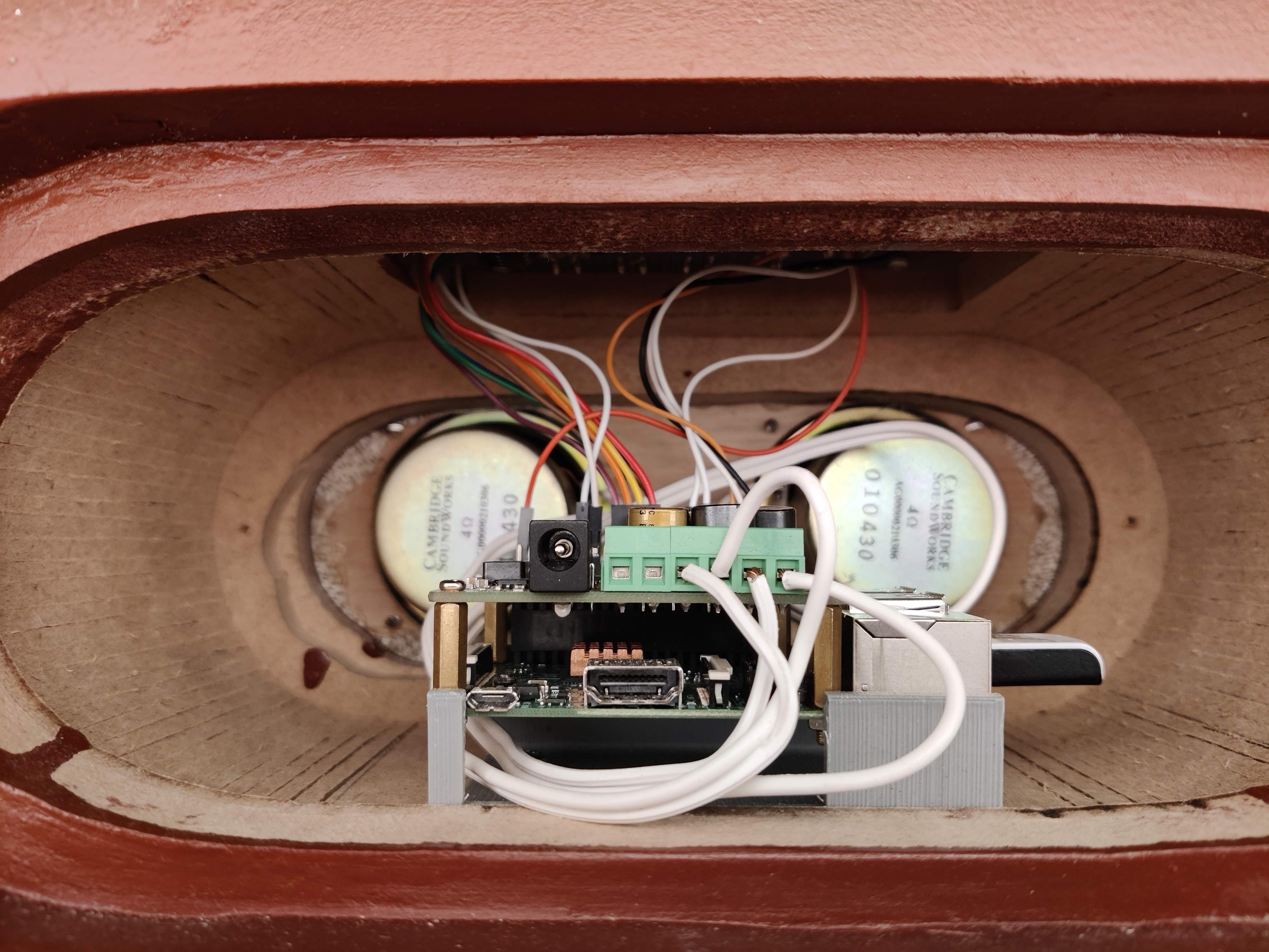
The final step for the enclosure: assemble everything!
This is straightforward. I made everything with simple connectors. I just had to branch all components of the control plate up to the pi correctly, put the plate in its spot, wire up the speakers and click the pi into its clamp.
The Puppets
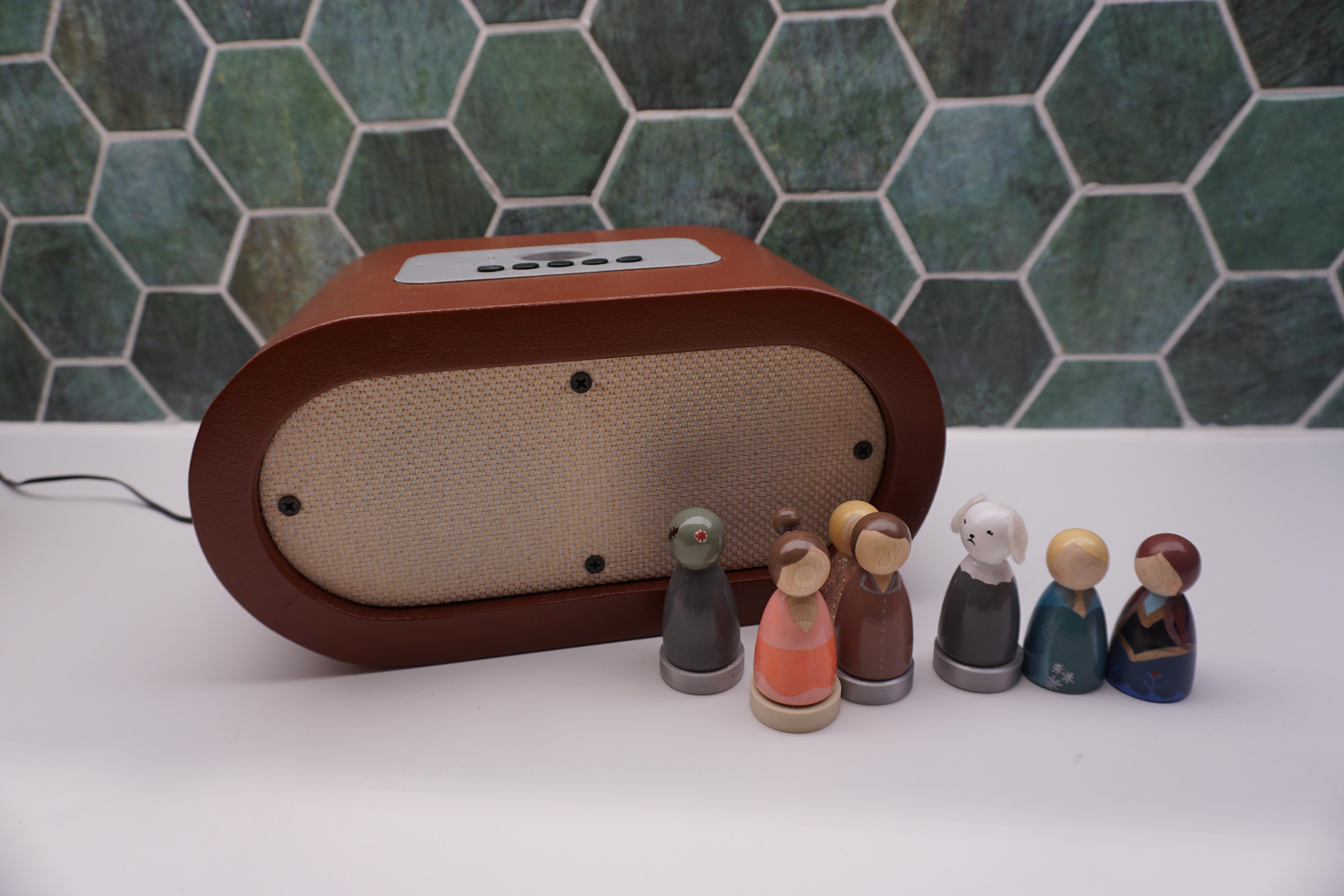
The last thing to do is choosing or making puppets that represent the playlists and appointing the playlists to them.
The puppets in the pictures were handmade by a family friend. I wanted all the puppets to represent the singers or movie or the song, yet all of them to be in the same style. So after a lot of searching and even trying to design some with Fusion (big fail), we had the idea to ask her, since she makes and sells families of puppets made to look like your own family. She made Elsa and Anna to represent the Frozen I and II soundtracks, a little Zombie for the Cranberries (the kids absolutely love Zombie), a ballerina for the Ballerina movie soundtrack, Samson (a Belgian singing TV dog) and a little feller in pajamas for Umberto Tozzi's Ti Amo (pa-jaaah-mah.... you get the picture). The possibilities are endless, use your imagination here!
I chose to write a full Spotify URI on an RFID tag in the puppet's base, which has also been added as a printable file, because of customizability. The idea is that you can write it with an app on your phone, but for now my phone formats them in such a way that the Pi script cannot read them anymore. This is because I use the simplified libraries for the RC522 module. I will expand this later but it is what is is for now.
For now you have to use Mifare 1k tags with this program, in the factory format and with factory keys, and only write playlists to them using the Pi itself. If for some reason you accidentally format the tags wrong, the only app that I've found that can undo this is Ikarus Projects' MIFARE Classic Tool. You can use it to reset all the keys if necessary.
For writing tags, you'll need to create and run another script:
sudo nano /home/pi/RFID_Radio/Write_tag.py
And add the script, again thanks to PiMyLifeUp:
#!/usr/bin/env python

import RPi.GPIO as GPIO
from mfrc522 import SimpleMFRC522

reader = SimpleMFRC522()

try:
        text = input('New data:')
        print("Now place your tag to write")
        reader.write(text)
        print("Written")
finally:
        GPIO.cleanup()
If you now execute this script:
sudo python3 /home/pi/RFID_Radio/Write_tag.py
You'll be prompted for an input. Input a spotify URI which can either be a song, album or playlist URI in this format:
spotify:playlist:37i9dQZF1E8EjOu4PXKY8q
After hitting enter, touch the tag to the RFID module or if you've built a radio, insert the puppet into the socket, and the script will output 'Written'. Your puppet now contains music!
The Conclusion
There it is. After all these steps I have a reliably working radio and the kids love it. Granted, they switch playlists all the time but at least they can put on the music they want now.
I have already thought that it's a shame that I don't have a remote to turn the volume down or turn it off... How did people do this in the old days with their phonographs and record and cassette players and who knows what!?
While explaining the progress a few limitations and possible improvements surfaced, and I'll list them up here so I can look back if I'm really bored for things to improve.
- The design of the control panel can be improved upon. It wasn't too easy to attach all the electronics and connect everything to the Pi. I attached the individual printable files, but I can give you the whole project if you send me a message.
- The script should work with all kinds of RFID tags, not just the factory formatted MIFARE 1k. I should upgrade it so it doesn't use the SimpleMFRC522 library but the full one. Normally they should be smartphone-programmable then as well.
- The kids don't want to use the buttons. When a puppet is docked, it should start playing, when it is remove, stop playing. Volume should be a knob (add I2C ADC module) and not be controller via the http service because there's too much lag for volume control. So no pushbuttons, 1 volume knob.
- Maybe I can improve the sound quality by adding some baffle inside of the enclosure and making separate left and right chambers.
- Easier setup of WiFi and Spotify account for less tech-savvy people.
- Possibly add bluetooth or WiFi casting capabilities to be able to use it without the puppets? Mopidy is certainly capable of this.
So, that concludes my thesis. I'd like to thank my wife, my kids, my mom, ...
No really, a big thanks to all the people who create and maintain the tons of open source projects on which I'm able to build my little projects. I've tried to link to them as much as possible, my sincerest apologies to the ones I forgot. And also thanks to my brother for helping me understand what an API is and how to use it and for his excellent 3D printing services, and our friend for the brilliant puppets!
Please let me know if you make one and if you have or had any trouble! I'm very curious!