Quick Tips and Tricks When Making Fritzing Boards
5852 Views, 20 Favorites, 0 Comments
Quick Tips and Tricks When Making Fritzing Boards
If you haven't heard of Fritzing before then it might be time to check it out. Fritzing is an open source hardware program that allows the user to create a schematic based on components that companies have made such as the widely popular Arduino. It is very user friendly and can be very helpful when creating a circuit before actually making the circuit.
Fritzing has great option where you can add your own board you just have to create. There are three views that are required to make a board. You need the normal bread board view where it shows the entire board and all of its components. There's schematic view that has just the connectors and is black and white. The final view is creating a printable circuit board view.
The way I create some circuit boards is through the program Adobe Illustrator. While there are multiple ways of creating and editing the views I just prefer Illustrator. I have found some handy tips when using Illustrator for designing your board.
Simply Enough: Saving
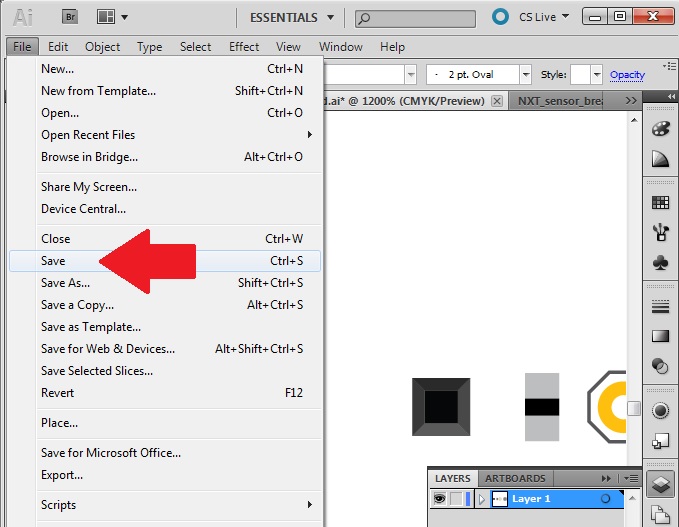

Always remember to save your work. You will save yourself a lot of potentially lost time if your computer crashes or if some other unexpected event occurs. But one of the main things to help with saving time is saving frequently used parts. any pin holes, connectors, or parts you've made will most likely be used again. I would be help to create a separate document that contains these parts. I would just copy the part created and paste it in this file and save it. Bring it up whenever you start making another board.
Also it might be best to save multiple copies of your work just in case. Maybe even put other copies on different devices like a flash drive.
Getting the Right Sizes (Bread Board View)
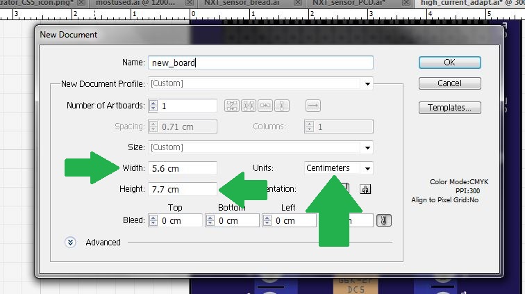
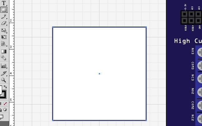
When creating a circuit board for Fritzing it is best to have measurements for the physical board or a board you plan on making. The Fritzing program will use the actual sizes of the document. Measure the perimeter of the board you will make and set size of your Illustrator file to that. Of course you can always make the size of the work area bigger it is just handy to know what sizes you are working with. Also sometimes it's difficult to get ride of white space
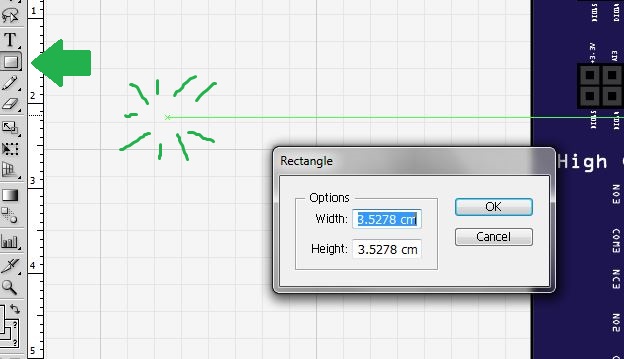
Make sure you measure your parts and the distance between the parts of your board. You want the most accurate representation of the board as possible. When creating a rectangle or other shape to use in your project it is best to use the tool then do a single click. This will prompt a window where you can input the size you want the shape to be. Try to make all the spaces between pins as similar as possible. The best way to do this is the transform options.
Transforming
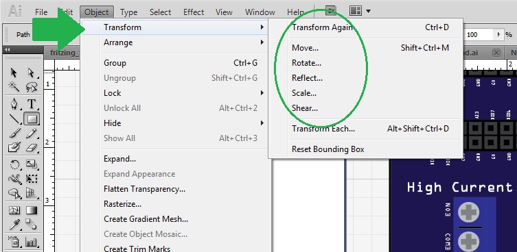
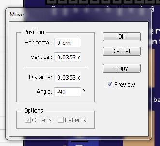
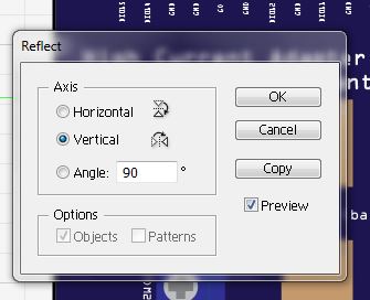
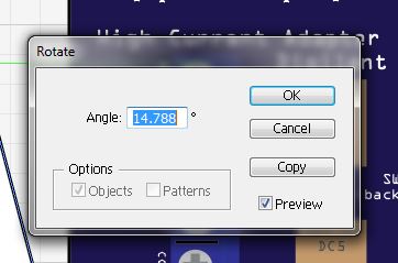
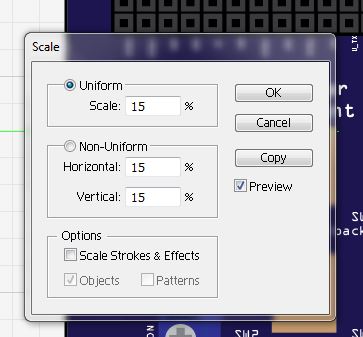
When you want to adjust an object's position, reflection, shear, scale, or angle you can click on the transformation option under the objects menu. One of the most useful things about this is that you can create a copy and transform that object at the same time.
If you want to make a row of pins that are equal distance apart can use the move function. Just start by clicking the object you want to copy and use ctrl+shift+M or cmd+shift+M for mac users. Once you have put how far you want to move the new object hit copy. Once you've done this command once you can pres ctrl+D to transform the copied object the same way you did to the first object. It's a very efficient way to create multiple objects at set distances.
Rotating is nice for rotating objects at exact angles as it is often hard to be accurate when using your mouse. Reflecting is great for flipping the orientation of that object. Scaling is perfect for keeping the shape of the object and just making it smaller or bigger.
Getting the Right Sizes (Schematic View)
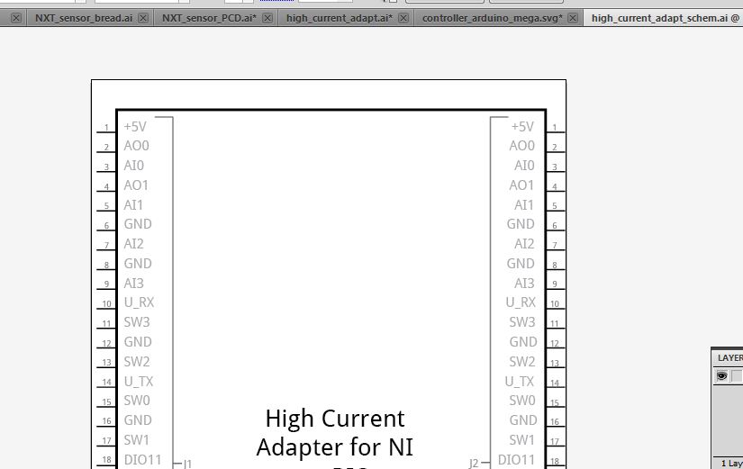
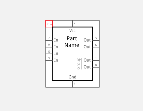
One of the other files that is needed is the schematic view. When creating the schematic view it is important to remember the correct spacing between the leads. The Fritzing website states that connectors should be about 0.1 inches (.254 cm) apart from each other. The connectors should also be about 0.1 inches long. Use the Move option to copy a single connector to multiple spots. Be sure to label all the connectors and number them correctly.
You'll want your work area to have enough room for all the connectors. What I like to do is figure out how many pins I want on one side of the schematic and then do some math. If I want 20 pins on the left side of the schematic then I'll need about 2 inches of space on that side. I would add a couple of .1 inches to that to make sure you have enough room for text.
Getting the Right Sizes (PCB View)
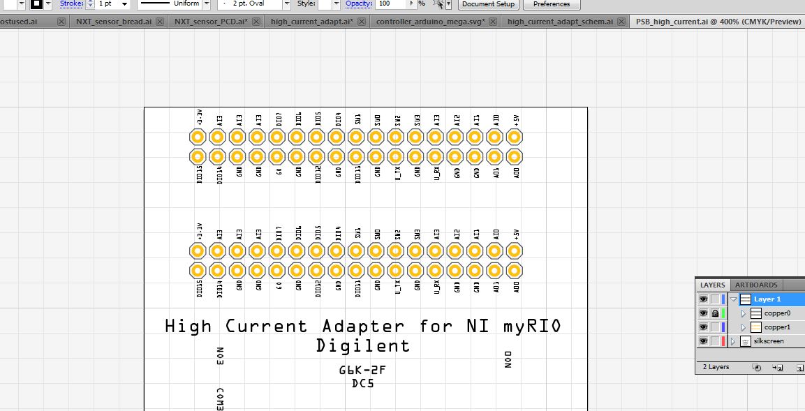

The final view that is needed for the program is the printable circuit board view (PCB). When creating the PCB view it is best to use the same size as the bread board view. Here the pins should be roughly the same spot as where the pins are on the bread board. On the Fritzing website it states that the pin holes should be about 1.5 millimeters in diameter. This means from the edge of the ring to the opposite edge. The hole in the ring is about 1 millimeter. The distance between each pin should be around 2.5 mm(.25 cm). I like to put a octagon around my holes because It looks just a tad bit cleaner. I use the polygon tool to create the octagon. If you use the arrow keys while making a polygon or just click once you can edit the number of sides the polygon has.
Text

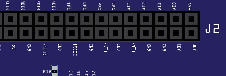

You will need to use the fonts provided by Fritzing for your text. You can download them here. After that just right click on them and hit install. The Droid Sans font goes on the schematic while OCR A font goes on the bread board.
One of the things I like to do that isn't required is put the name of pins on the PCB to make sure I don't loose track of my pins. I usually will just copy the text from one view to another file. Since the PCB layout should be the same or close to the same as the breadboard the text should fit nicely into place. Final step would be to make the text darker on the PCB view.
Layers
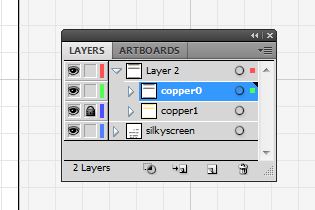
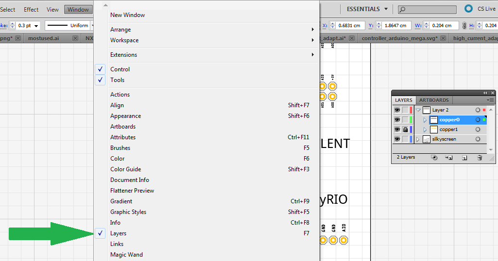
Use layers. This will be very helpful when trying to just work with a specific group of objects.
On the breadboard view it is best to have a layer for all of your text, a layer for all of the pins or holes you will be using, and a layer that will just be used to make the board look nice.
On the schematic I use two layers. One for all of the text and labels and another used for the connectors.
On the PCB i have two layers also but also sub-layers. I keep all the copper circles in one sub-layer and then the octagons in a different sub-layer. All the text will go into a layer called silkscreen. Name your layers how ever you please just make sure you understand what layer is what.
Final Step
I hope this is worthwhile and helpful. I will edit and add anything in the future. If you feel like I missed anything that could be helpful please let me know. Feel free to comment and give feedback. This is my first Instructable so I hope it was helpful. I am using the CS5 version of Illustrator so keep that in mind.
Go check out the Fritzing website when you get a chance. It's a great program to help you design your circuit before you build it.
Take a look at this Intro Fritzing Instructable for a better understanding of how to use the program. Also check of their other guild of how to Create Your Own Parts in the program.