Quick Start Guide for ESP32-S3 2.8inch Capacitive Touch Display Development Board
by Flameling01 in Circuits > Arduino
5985 Views, 6 Favorites, 0 Comments
Quick Start Guide for ESP32-S3 2.8inch Capacitive Touch Display Development Board

The Waveshare ESP32-S3-Touch-LCD-2.8 is a 2.8-inch touchscreen development board with a resolution of 240x320.
The ESP32-S3 chip gives us Bluetooth 5 (LE) and WiFi (2.4 GHz) connectivity.
The onboard touchscreen can run GUI applications, which can be made comfortably using EEZ studio.
The complete list of features can be found on the official website:
https://www.waveshare.com/esp32-s3-touch-lcd-2.8.htm
https://www.waveshare.com/wiki/ESP32-S3-Touch-LCD-2.8
This guide aims to aid you in setting up the development environment for this board in Arduino IDE by simplifying the official instructions.
Note: Waveshare has removed the libraries from their website (Step 4 of this instructable). You can find them in my GitHub repository: https://github.com/dipenarathod/ESP32_Waveshare_2.8in_display under 'Display Libraries.zip'
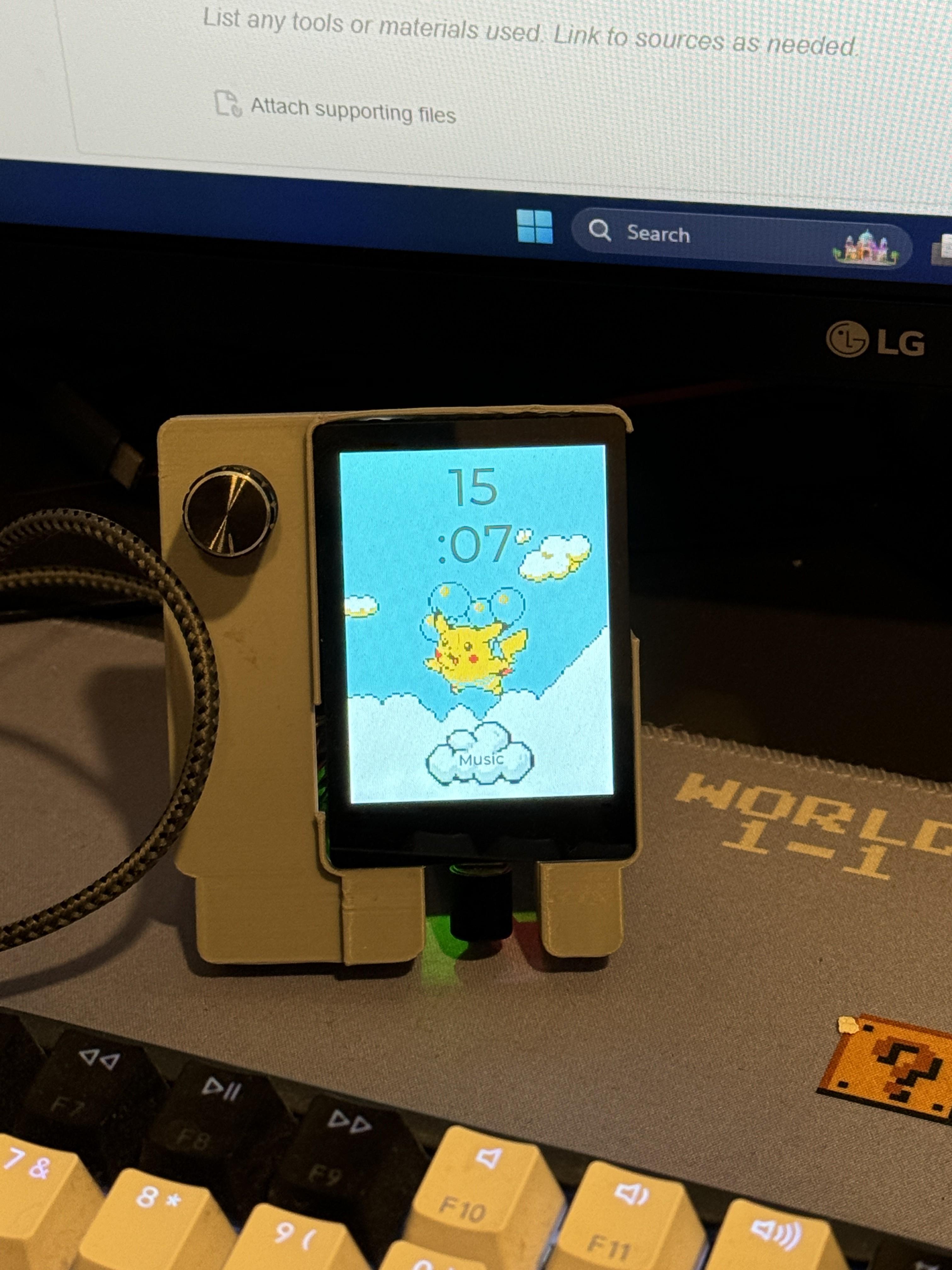
Completed: I may make a short tutorial using EEZ studio to make multi-page GUI applications with animated backgrounds. The floating Pikachu animated clock face was made using EEZ studio.
Link: https://www.instructables.com/ESP32-Touch-Display-Multipage-Macropad/
The board can also send keyboard strokes to the connected computer via HID. The rotary encoder controls the volume of my PC.
Supplies
- Waveshare ESP32-S3 2.8inch Capacitive Touch Display Development Board
- A machine with Arduino IDE installed. I am using a Windows 11 PC, so the instructions here may not apply directly to Linux and MacOS users. My Arduino IDE version is 2.2.1
Selecting a New Project Folder Location
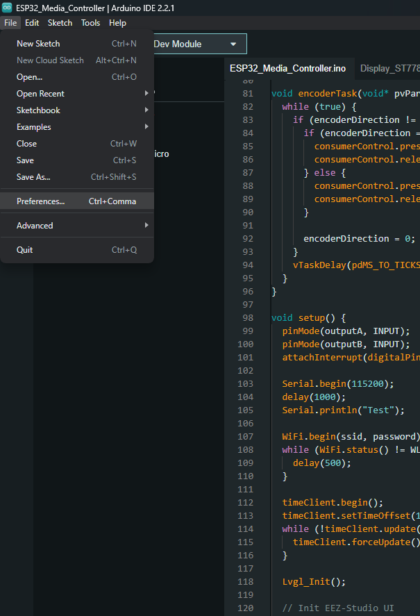
- Open the Preferences menu (refer to image 1 of this step)
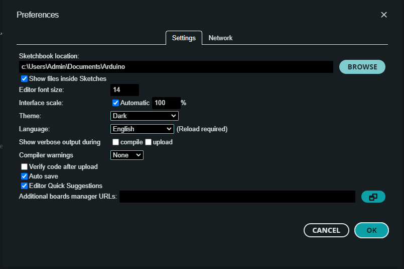
- Press Browse to select a new Sketchbook location (refer to image 2 of this step)
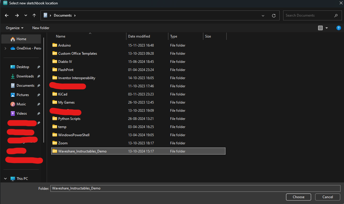
- Create a new folder for your Sketchbook. I created a new folder called Waveshare_Instructables_Demo in my Documents folder (refer to image 3 of this step)
- Select that folder and press OK to exit the preferences menu.
Adding ESP32 Via the Boards Manager
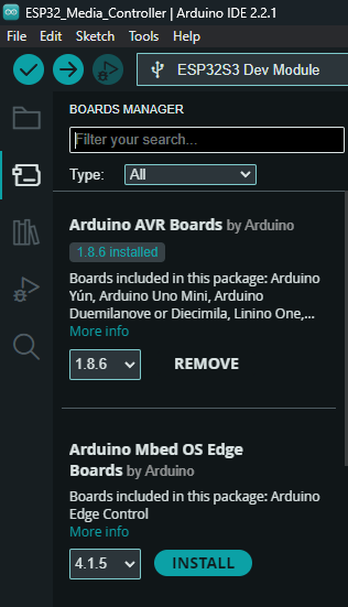
- Select the Boards Manager from the left side menu (refer to image 1 of this step)
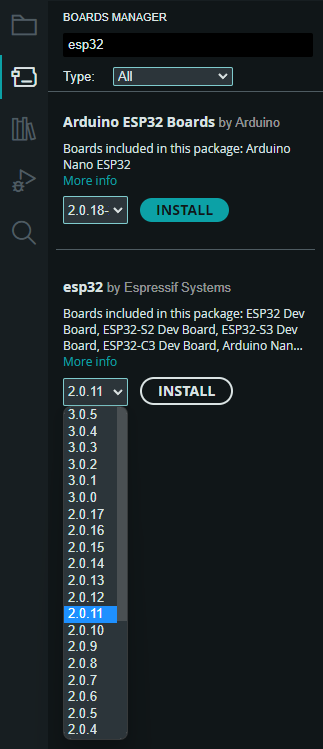
- Search for ESP32 and download version 2.0.11 (refer to image 2 of this step)
Installing Libraries
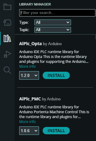
- Select the Library Manager from the left side menu (refer to image 1 of this step)
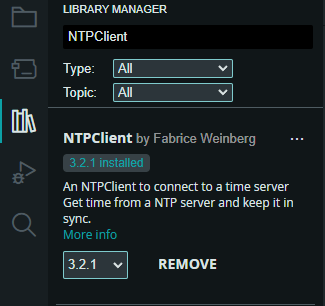
- Install the NTPClient library by Fabrice (Version 3.2.1) (refer to image 2 of this step)
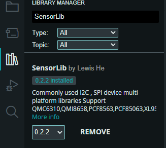
- Install the SensorLib library by Lewis(Version 0.2.2) (refer to image 3 of this step)
Downloading and Saving the Waveshare Libraries
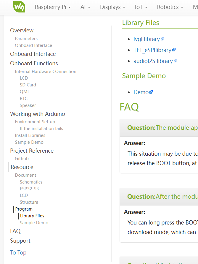
- Download the three libraries shared by Waveshare (refer to image 1 of this step)
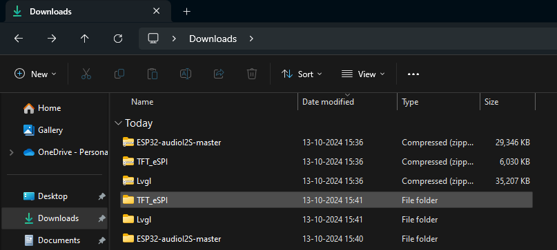
- Unzip the three libraries (refer to image 2 of this step)
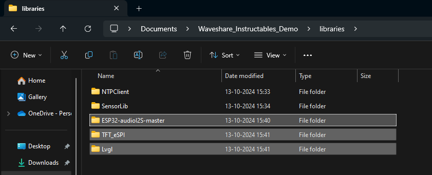
Navigate to the Sketchbook you created in Step 1. There should now be a libraries folder containing the two libraries installed in Step 3.
- Copy the unzipped library folders into this 'libraries' folder (refer to image 3 of this step)
Downloading and Saving the Sample Demo File
- Download the sample demo file shared by Waveshare (refer to image 1 of the previous step to see that the demo file is just below the libraries)
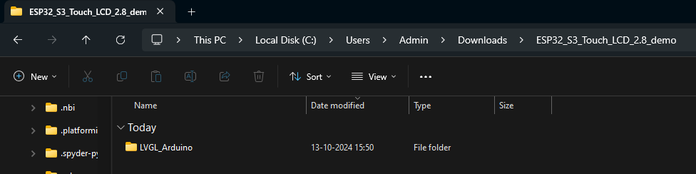
- Unzip the demo file folder and there must be one folder called LVGL_Arduino inside it (refer to image 1 of this step)
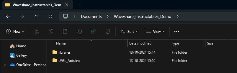
- Copy the LVGL_Arduino folder to your Sketchbook (refer to image 2 of this step)
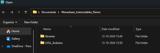
- In your Arduino IDE, select File -> Open -> (navigate to your sketchbook location if necessary) -> Open the LVGL_Arduino folder (refer to image 3 of this step) -> Select the LVGL_Arduino Sketch
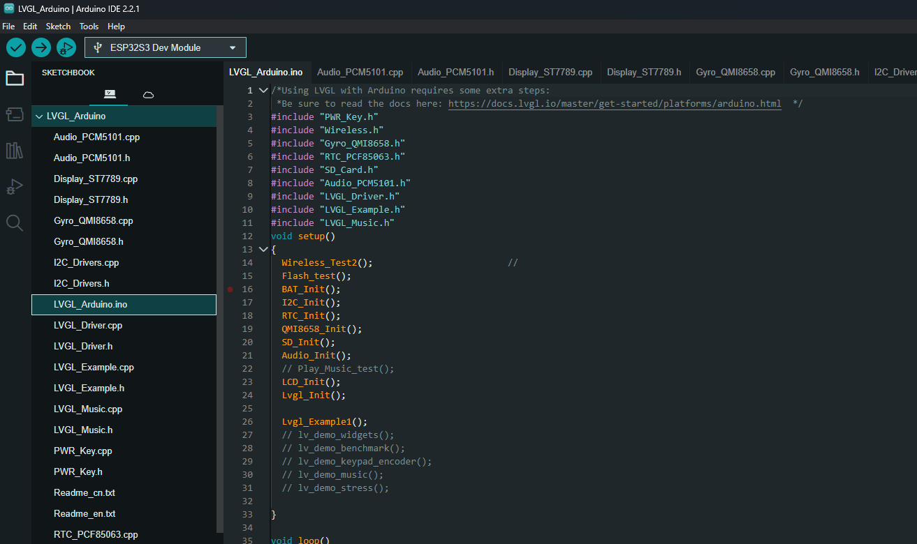
- All relevant .cpp and header files must open along with the LVGL_Arduino.ino file (refer to image 4 of this step)
Selecting the Board and Its Settings
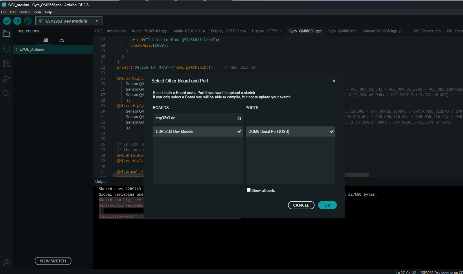
- Select ESP32S3 Dev Module as the target board (if it is not selected automatically after connecting the device) (refer to image 1 of this step)
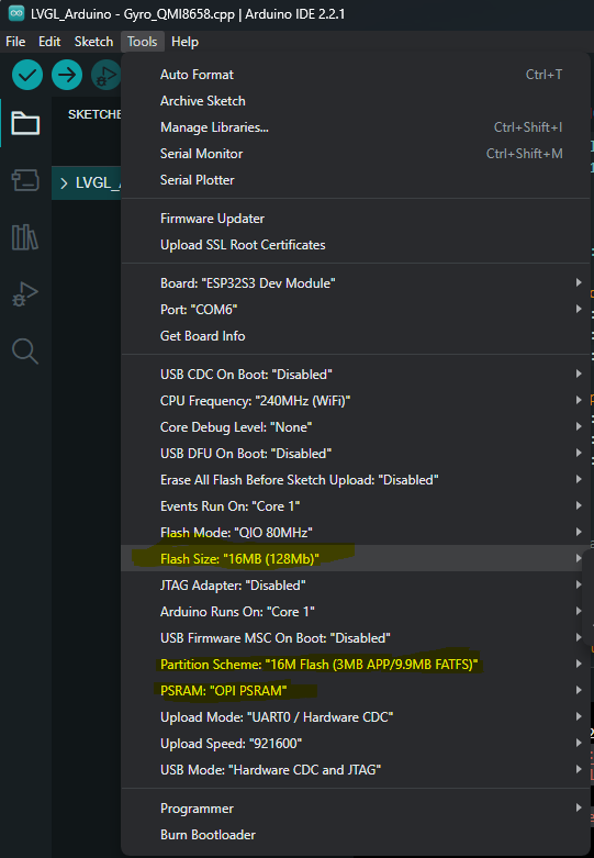
- Set the correct board settings.
- Go to Tools and make the settings match the ones in image 2 of this step. Pay more attention to the settings highlighted in yellow.
Verifying the Code and Solve Potential Errors
Set the correct Board Settings.
Press the Verify Button to verify the code (Tick mark button on the upper west side)
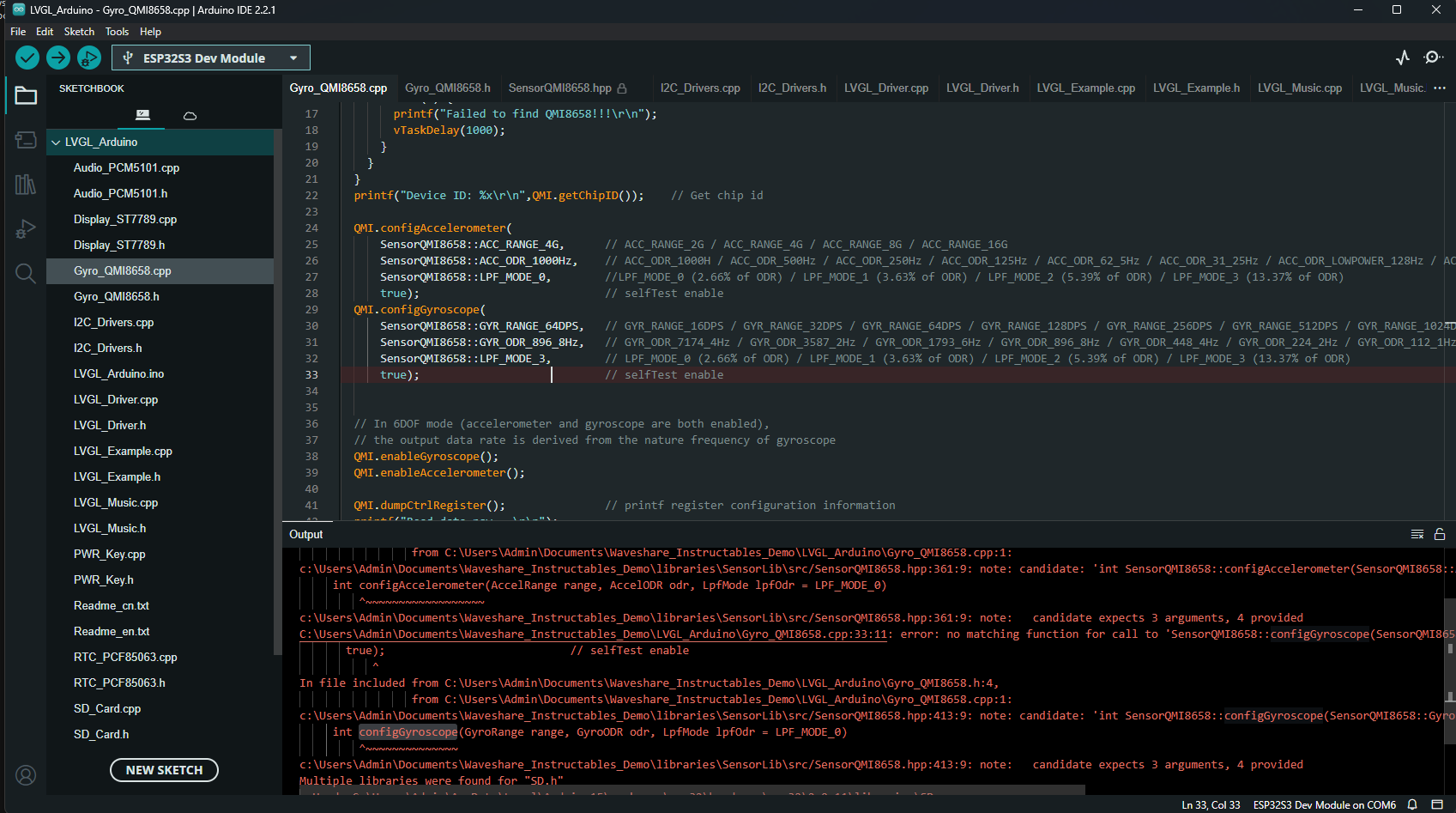
I got a few errors while compiling. All of them were due to the configAccelerometer and configGyroscope method calls in Gyro_QMI8658.cpp (refer to image 1 of this step)
Removing true (the last argument to these functions) fixed the problem for me. You can go to the function definition to see that these functions do not have a fourth argument.
Uploading the Code
Put the device into programming mode:
- Press and hold the RESET button
- Press and hold the BOOT button
- Release the RESET button
- Release the BOOT button
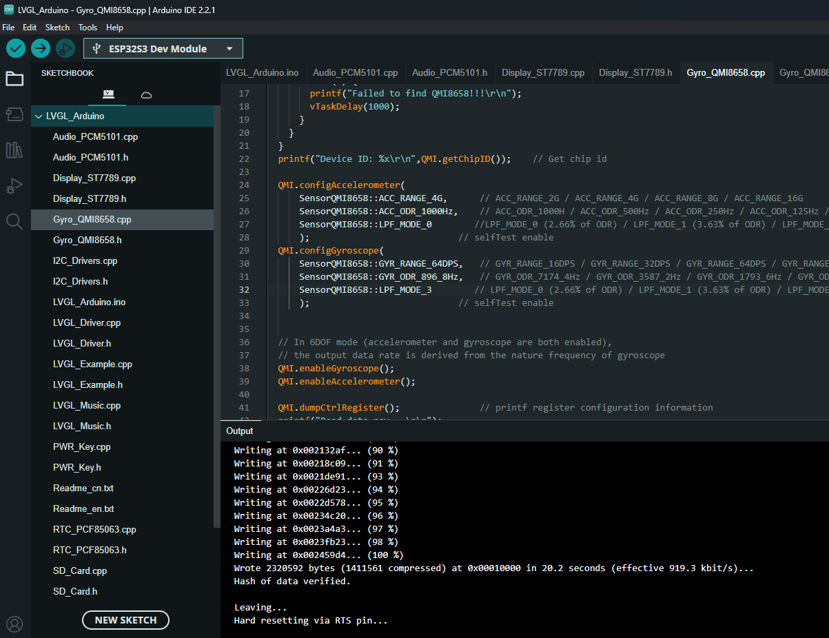
Select the COM port your device is connected to and upload the code.
You should get an output in the terminal similar to the one in image 1 of this step.
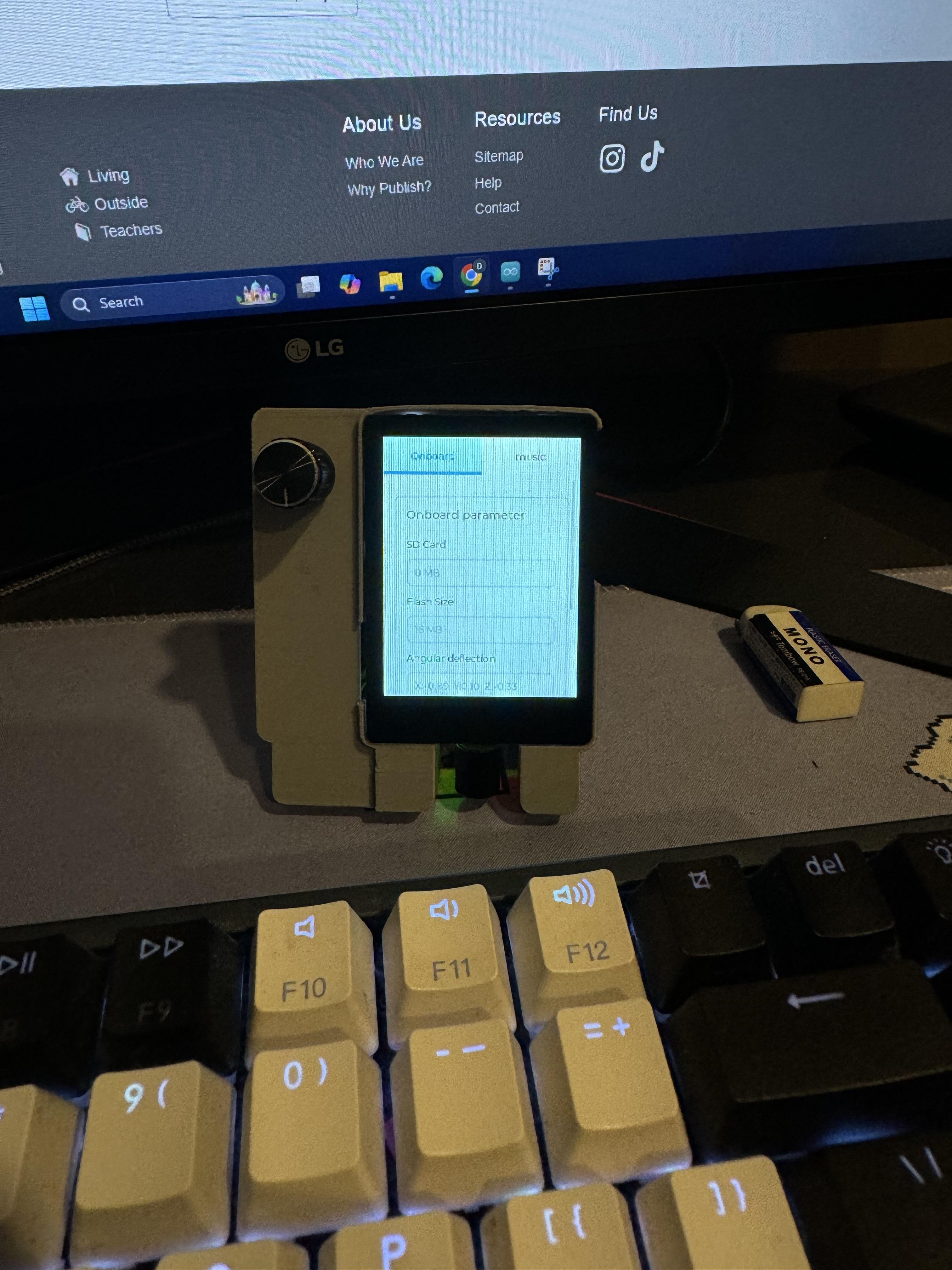
The screen may stay off. Press the RESET button in case it is.
You should see the same thing as shown in image 2 of this step