Quick & Easy Wood Backed Neon Signs Using EL Wire
4890 Views, 62 Favorites, 0 Comments
Quick & Easy Wood Backed Neon Signs Using EL Wire

Hello fellow makers,
In this Instructable I will be showing you how I make these neon signs. They are really quick to make, consume very little electricity and I personally love the wood backing of the signs instead of the clear acrylic usually used.
Most of the neon signs available today is made from LED neon strips and while they can look great they are a little too "harsh" for me, whereas EL wire has the same beautiful glow as real neon tubes and can be formed much more freely.
One issue I ran into with EL wire is the inverter used to power them, while you do receive one with your wire and there are a lot of them available for dirt cheap they all have a very annoying problem....they SQUEAL!
To solve this issue I started making my own inverters to power them, it consists of only 4 parts and is really easy to make plus they are way brighter compared to the ones I got included with my EL wire.
Let's get making!...

You Will Need:

To replicate this Instructable you will need:


- Wood planks
I used some reclaimed pine floor boards that I planed on both sides but you could even use old pallet planks.
- Access to a CNC machine
- EL Wire
Amazon - EL wire with inverter
- Linseed oil
- Sandpaper
Amazon - Sandpaper pack various grits
Optional:

- Access to a 3D printer
- Paint
For the inverter:


- Inductor/choke
I get mine from discarded CFL bulbs.
- Insulated copper wire
- NPN transistor
Amazon - High current NPN transistor
- 1K resistor
- Capacitor
*As an Amazon Associate I receive a small percentage from sales made through provided links at no cost to you, this helps fund future projects.
What Is Electroluminescence?

Electroluminescence (EL), production of light by the flow of electrons, as within certain crystals. Electroluminescence is one of the few instances in which a direct conversion of electric energy into visible light takes place without the generation of heat, such as occurs in the incandescent lamp.
There are two distinct mechanisms that can produce electroluminescence in crystals: pure or intrinsic and charge injection. The principal differences between the two mechanisms are that in the first, no net current passes through the phosphor (electroluminescent material) and in the second, luminescence prevails during the passage of an electric current.
In intrinsic electroluminescence, thermal activation and the electric field liberate atomic electrons (from donor levels) into the conduction band. Many of these conduction electrons are accelerated by the field until they collide with luminescent centres, ionizing them (i.e., ejecting electrons from their atoms). Light is emitted in the normal way as soon as an electron recombines with an ionized atom of the centre. Because the effect dies away when constant voltage is applied, an alternating voltage may be used to create a sustained light emission.
Electroluminescence can also result from charge injection, as when an electrode contacts a crystal to provide a flow of electrons or holes (electron extraction) or a voltage is applied to a p–n junction causing a current to flow; i.e., electrons flow from the n-type material into the p-type material. In both cases, the electrons lose energy when recombining with centres or positive holes accompanied by the emission of light.
Source: Britannica
Design Your Neon Sign:

First thing we will need to do is to design our neon sign.
When I'm busy with my CNC jobs I use Aspire as I'm familiar with the interface but you can also use Fusion 360 for all of your CAM needs.
For the design we'll basically just need to type the word or phrase for our sign and add a cutout around it, this can be any shape you want.
I also like to add a drill point to the start and end of my word/phase, that way it hides the start of the EL wire and you can also feed through the end to the back of the board.
For the neon signs I use the following font: NEON (download, extract and double click to install)
I size the lettering so that it is 3mm wide and my CNC can machine it in a single pocket cut with a 3mm cutter and 3mm deep.
Time to Carve:


With the sign design and gcode generated we can get cutting.
The best way for me to attach the wooden planks to the machine is by sticking painters tape onto the back of the plank and also onto the machines bed, then using 2 part CA glue simply stick the plank onto the machine bed.
When you're done the plank can simply be peeled off with no damage to the wood or machine.
To carve the sign I used a 3mm 2 flute upcut bit.

As I'm using a homebuilt DIY CNC that is built from 3D printed it is not the sturdiest and I had to go slow but it still only took 30 minutes to complete the sign.
Refine the Board:

After carving there will be some imperfections that will need correcting.
Due to the wood I used I had quite a lot of splintering that needed to be sanded away.
I used some 220 grit sandpaper to sand down the entire piece before applying a light coat of linseed oil to protect the wood.

I try to not get the oil into the carved grooves as it will prevent the glue from adhering to the wood when inserting the EL wire.
Building Your Own EL Inverter:


This step is completely optional and you can use the inverter that is included with the EL wire, but if you are sensitive to high pitched sounds I would highly recommend making your own.
First we are going to have to disassemble the choke, start by removing the tape that is wrapped around the dark grey core.

The core consists of two "E" shaped pieces that can be pulled apart and away from the winding, if there is glue holding them together you can soak it in a bit of IPA to loosen. With the coil exposed you need to wrap a new coil around the existing one with the enameled copper wire, start with twenty turns make a tap and then another twenty turns.

You can now re-wrap your new coils in some kapton tape or just drop some CA "super glue" onto the windings to keep them in place.
Now that you have your high voltage blocking oscillator transformer we can assemble the circuit as shown in this schematic.

Insert the EL Wire:

We can now start assembling our neon sign.
Apply a drop of two part CA glue to the end of your EL wire and insert it into the hole on either end of your lettering (depending on which side you want the inverter to be).
Now start laying the EL wire into the channel that has been carved, I have found that the bends hold the EL wire in place very well and I only have to apply some glue on long straight parts where the wire tends to bulge out.

When you're done laying down the wire feed the end through the second hole and leave about 10cm out the back of the wood panel before trimming the excess.

How to Solder EL Wire:

Soldering new connection wires onto your EL wire can be quite tricky with the thin corona wires, here's how I do it.

First we'll need to remove the outer coating. They usually have two protective layers over the wire, the first one (this is usually the coloured one, clear in my case as I ordered white ones) is easy to remove with your wire stripper but the next layer protects the two fine corona wires. This is the hardest part of the process so don't be disappointed if it takes a few tries to get it right.
If you accidentally cut off one of the corona wires (or both) cut the core and try again. Upon success you should have three wires sticking out.

Cut a 5mm or so piece of copper tape.
Unwrap the tape from the backing and stick it right next to the edge of the stripped EL wire. Fold the two thin corona wires onto the copper tape.
Heat up your soldering iron and make sure its hot by melting solder onto the tip, it should melt easily. Now press the tip of the iron to the two wires and copper tape and quickly dab some solder in. Then remove the iron. This should not take more than a second or two or the EL wire casing will melt.
Now that the corona wires are soldered we can work on soldering to the middle wire. First we must remove the phosphor, by scraping it off. I like to just scrape it with a razor until we have a clean copper wire. Only clean about half of the exposed wire, we dont want to scrape it back all the way to the corona wires.
Now tin the wire by heating it up with the soldering iron tip and melting solder onto the wire.

Finally you can solder on some wires and slip over a piece of heat shrink to protect your connection (I highly recommend using heat shrink with hot melt glue inner as it reinforces your connections).
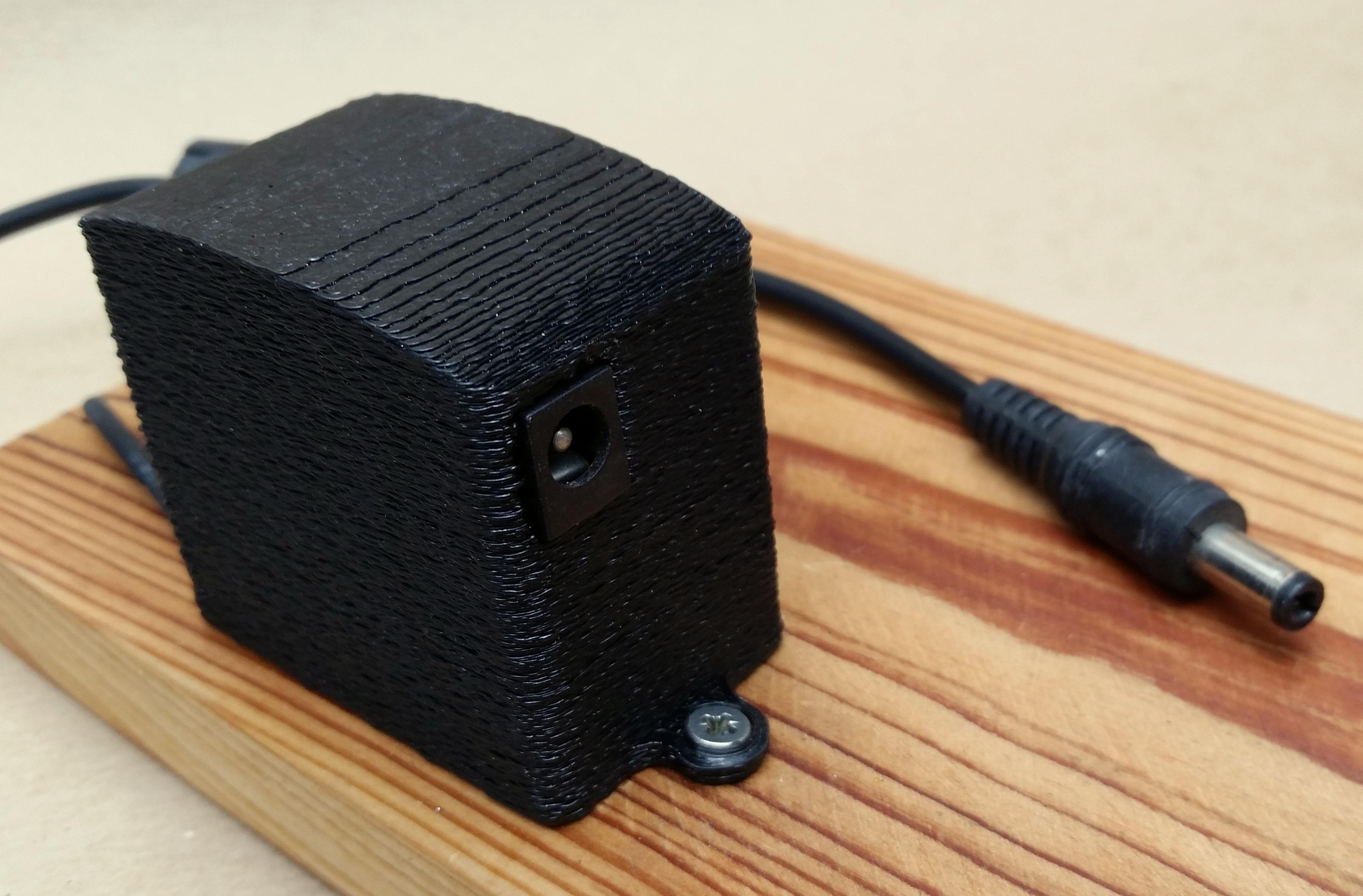
Inverter Enclosure:

To protect our inverter and also create a stand for the sign I headed over to Tinkercad to design an enclosure.
The enclosure is oversized to fit a wide veriety of inverters and you can also easily modify the design on Tinkercad.
I printed the enclosure with SBS filament as it will be exposed to the sun and also enabled "fuzzy skin" to hide the layer lines.

To power the sign I added a 2.1mm DC socket to the inverter as they are widely available and you probably already have some power adaptors lying around at home.
Downloads
Additional Information:

- To make the EL wires output brighter you can paint the inside of the carved channel white to reflect the light as pictured above.
Enjoy Your New Sign:


You can now go ahead and plug in your beautiful new neon sign and let it glow!

I hope you guys find this Instructable useful and if you have any questions please feel free to leave me a message or comment bellow.
Please share your own creations with us by clicking the "I Made It" button below.
Happy making!
---