Quick 3D Topographical Site Map CNC
by eliwilliams1337 in Workshop > CNC
5649 Views, 24 Favorites, 0 Comments
Quick 3D Topographical Site Map CNC

This is a quick how-to on creating a site topographical model and prepare it for fabrication using a CNC machine.
Software used: Sketchup (Free), Fusion 360 (Free to Students, Start-ups and Educational Institutions)
Topographical Models have a long legacy in the fields of Architecture and Design and can be great tools to communicate either a certain love of place or an idea that can not be shown in 2D. This process bypasses the use of Topographical Lines extrusions and jumps straight from an exported Mesh to a CNC ready file.
This tutorial assumes no knowledge of the use and functions of CAM and 3D modelling software and requires the assistance of Shop Techs to help reach conclusion
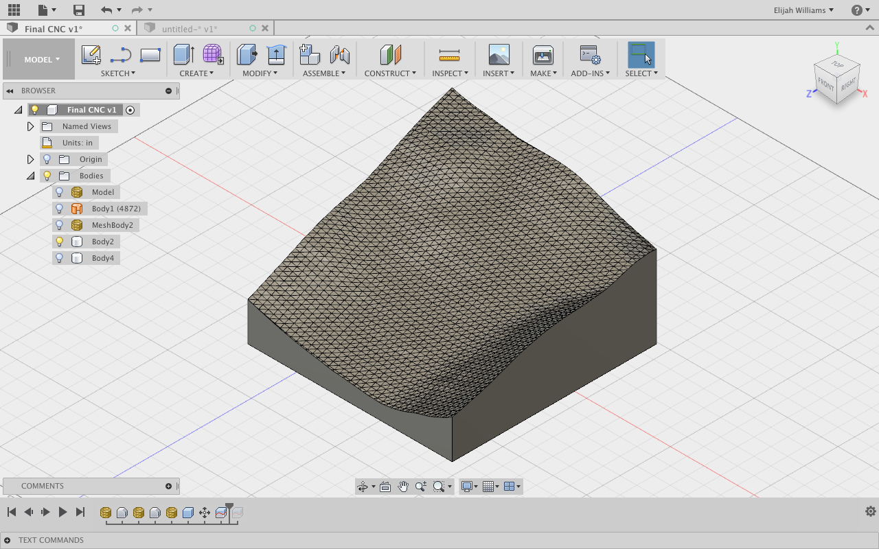
3D Topographical Final Model example on Step 6!
Exporting Topographical Mesh From Sketchup
Our first step is using a quick trick in the free version of the modelling software Sketchup:
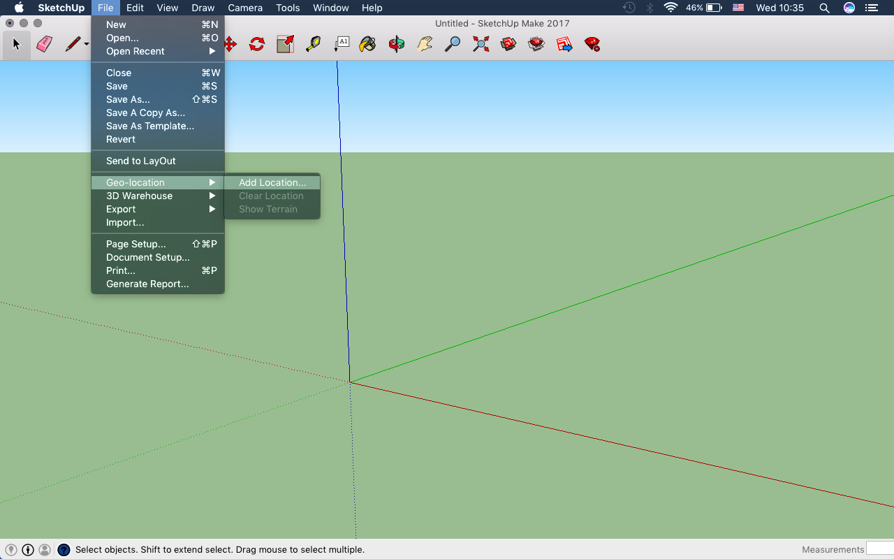
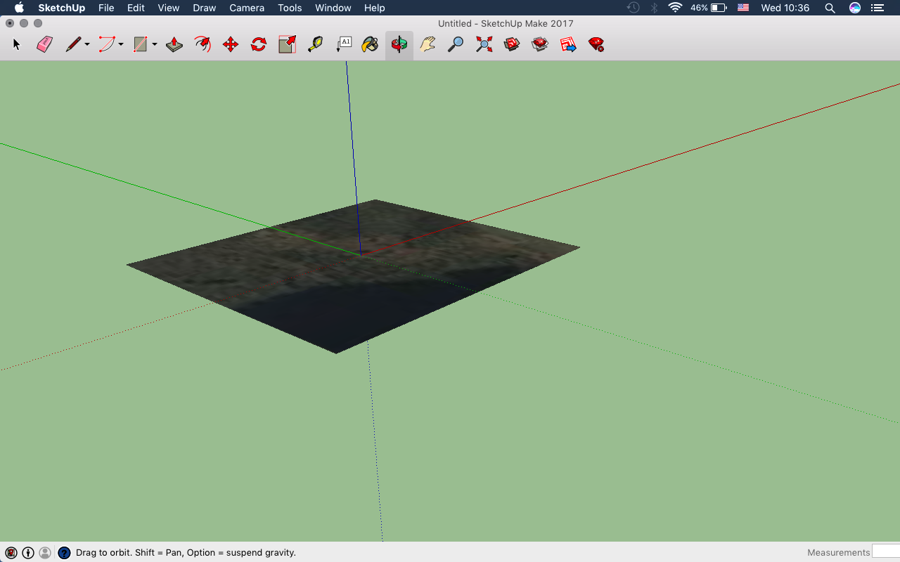
Open Sketchup, and under the File tap select Geo-location and then Add Location (Image 1).
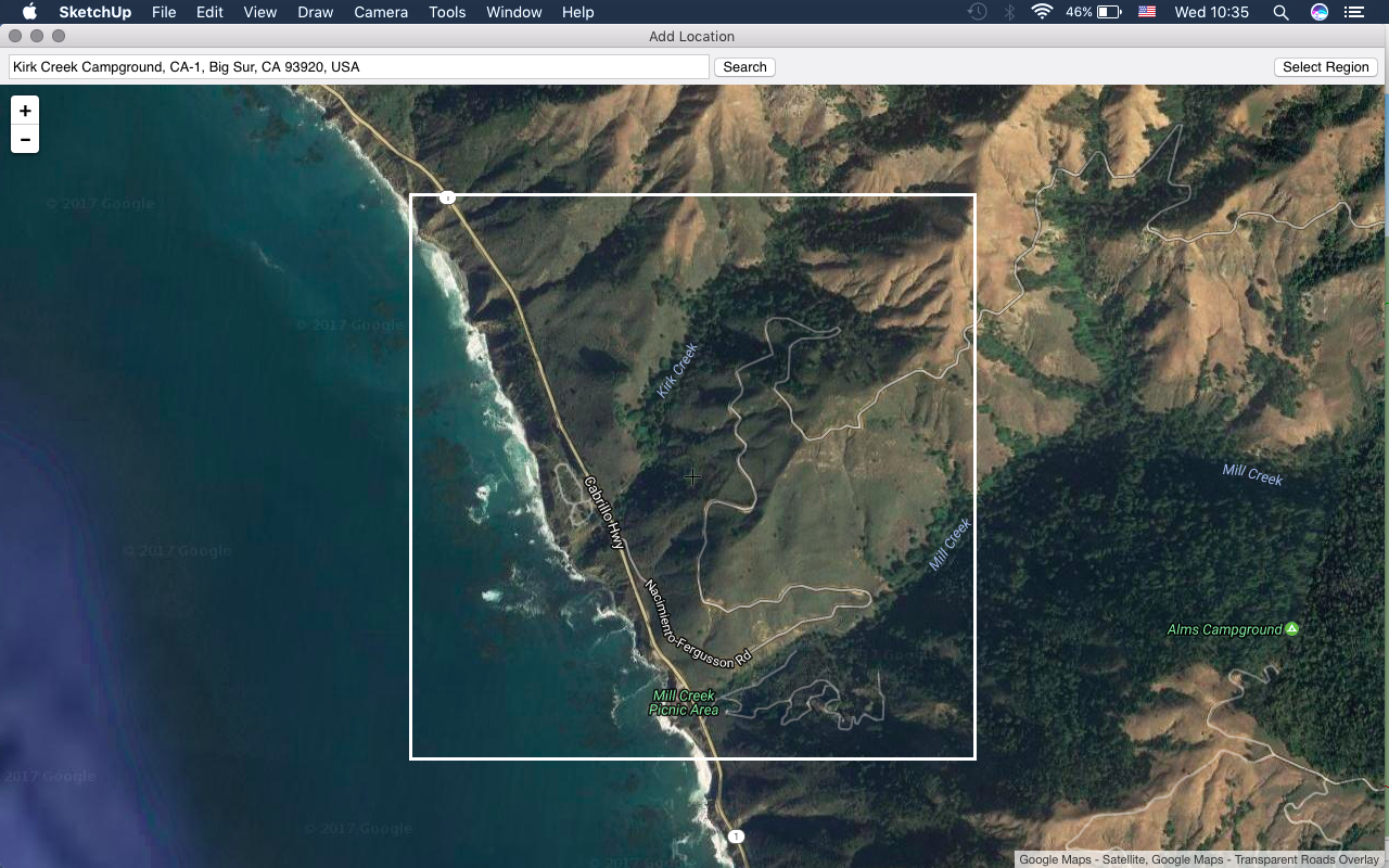
The Add Location menu will open a simplified version of Google Maps that will allow you to select any location visible on Google Earth through a search command in the top bar. Once you have found your region, click Select Region in the upper right hand corner (Image 2).
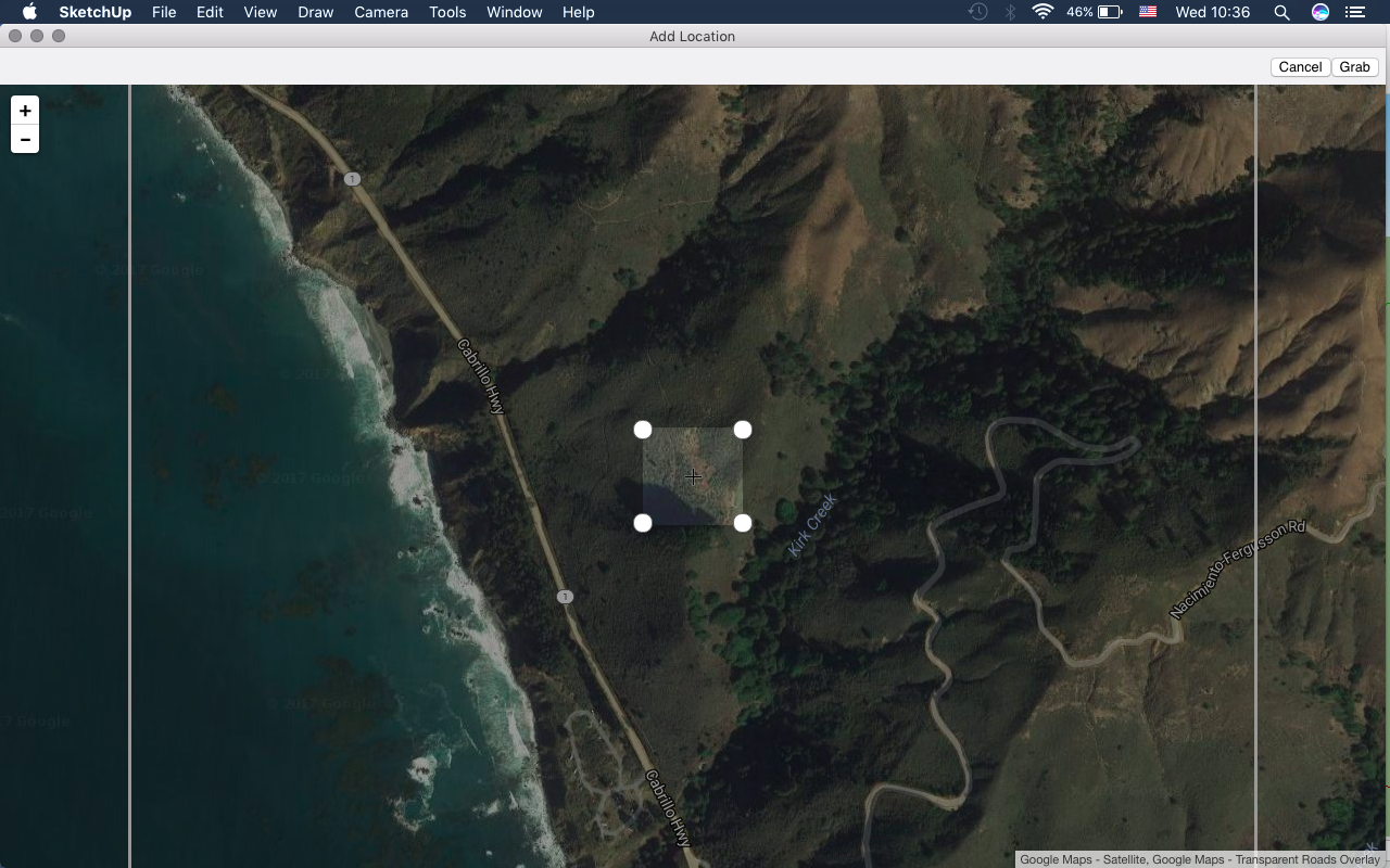
After you have selected your Region four white tabs will appear to help you crop the area you wish to be exported. (Image 3)
Note: The maximum area that can be selected is 2 kilometers or the extents of the screen.
After clicking Grab, this patch will appear in your navigation menu with the correct scaled units. This can make the process easier when importing it because you will be able to measure the height of elements in the Topographical model and scale accordingly. When we bring this file into Fusion 360 we will use these units to help convert to our desired final model size (Image 3).
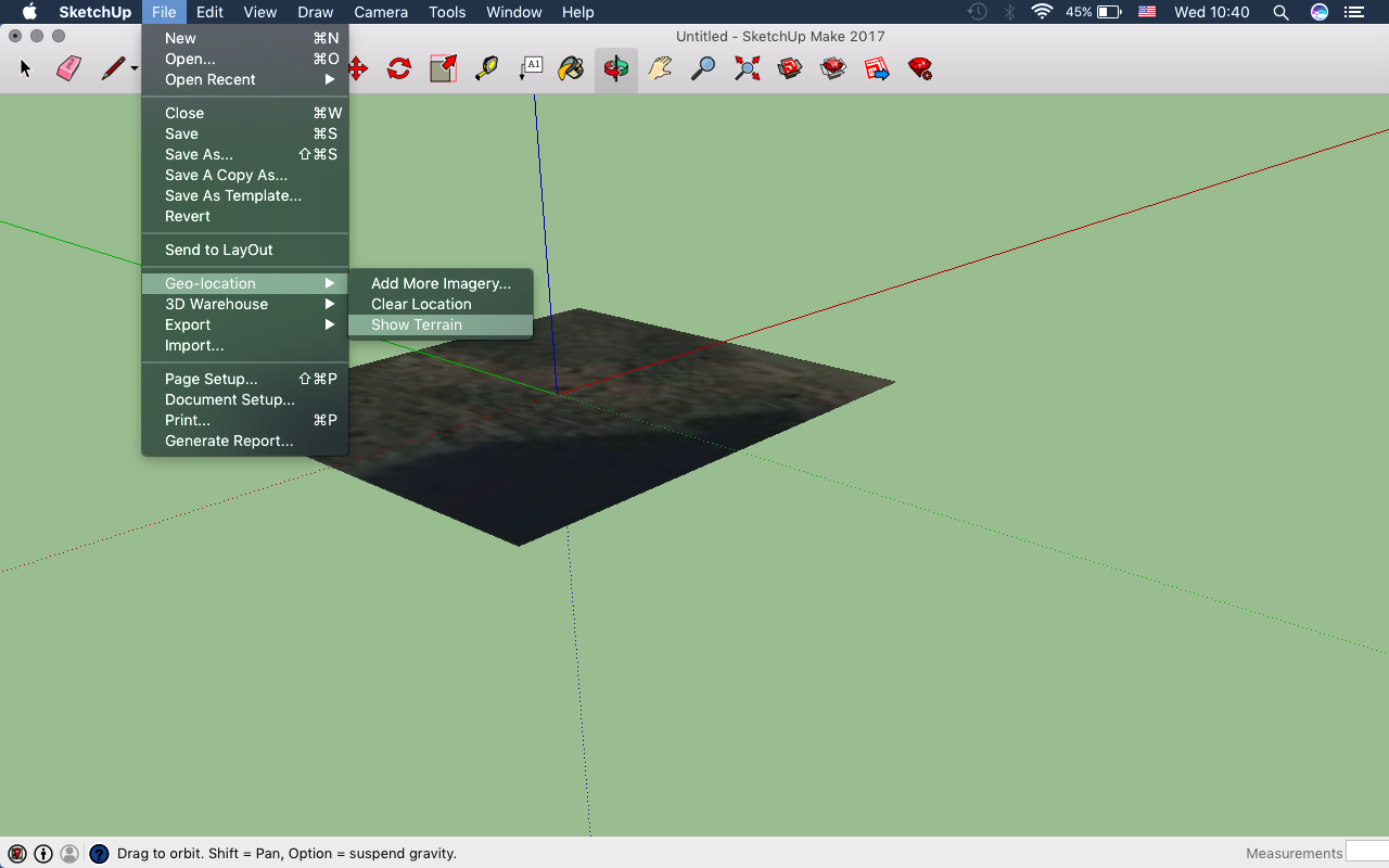
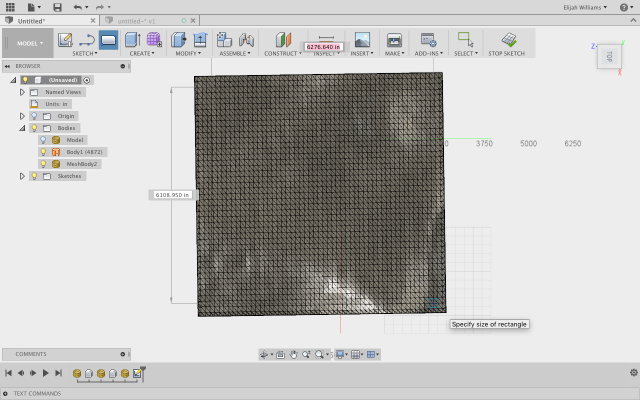
A 2D image will appear in your work space with a bitmap of the plot of land you have selected (Image 3). From here select File, Geo-location and then Show Terrain. This will access googles data on what the topographical composition of the area you have selected looks like (Image 5).
One of the benefits of this method is that the object that is created is already a Mesh which is a 3D modeling friendly geometry.
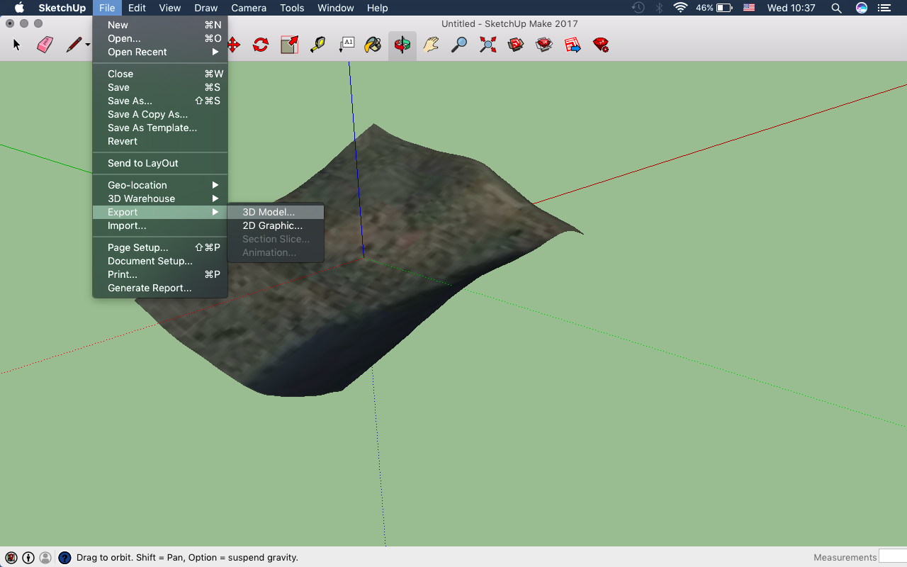
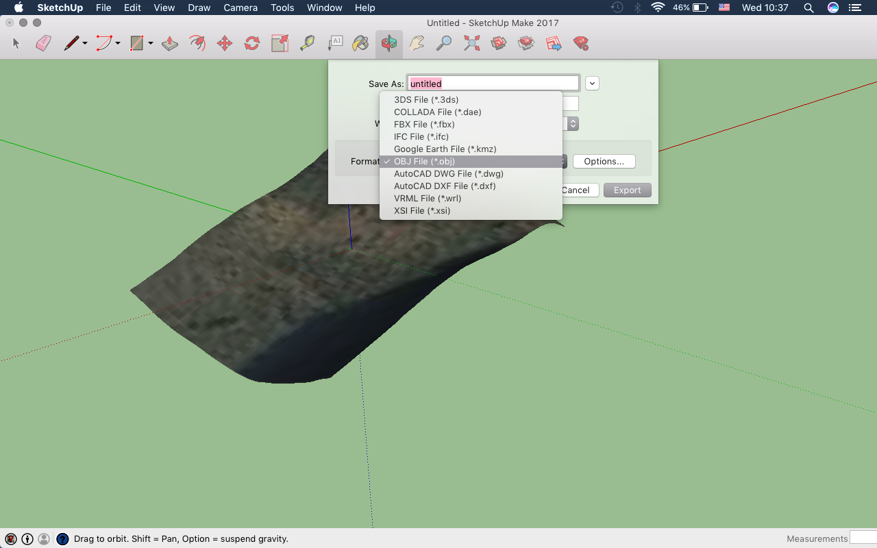
Now under the File tab select Export and then 3D model. This is the final step in the Sketchup part of the setup, exporting the file to an OBJ.
Choose a destination for the file and make sure to select OBJ as you file type.
Now that you have this file saved and ready we will open Fusion 360
Importing Mesh to Fusion 360
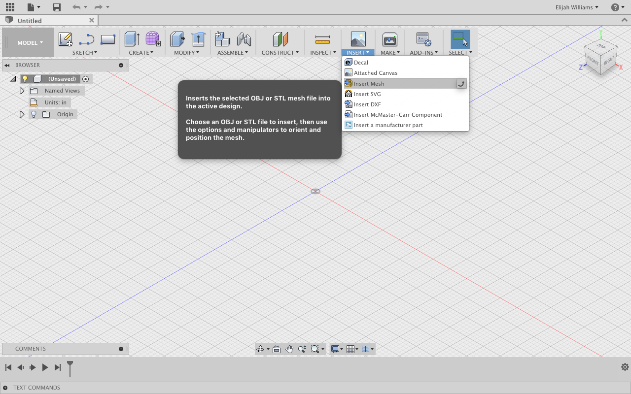
When we first open Fusion 360 We will see an Insert tab across the top of the screen. Select Insert Mesh from this menu and select your .OBJ file saved from Sketchup (Image 1).
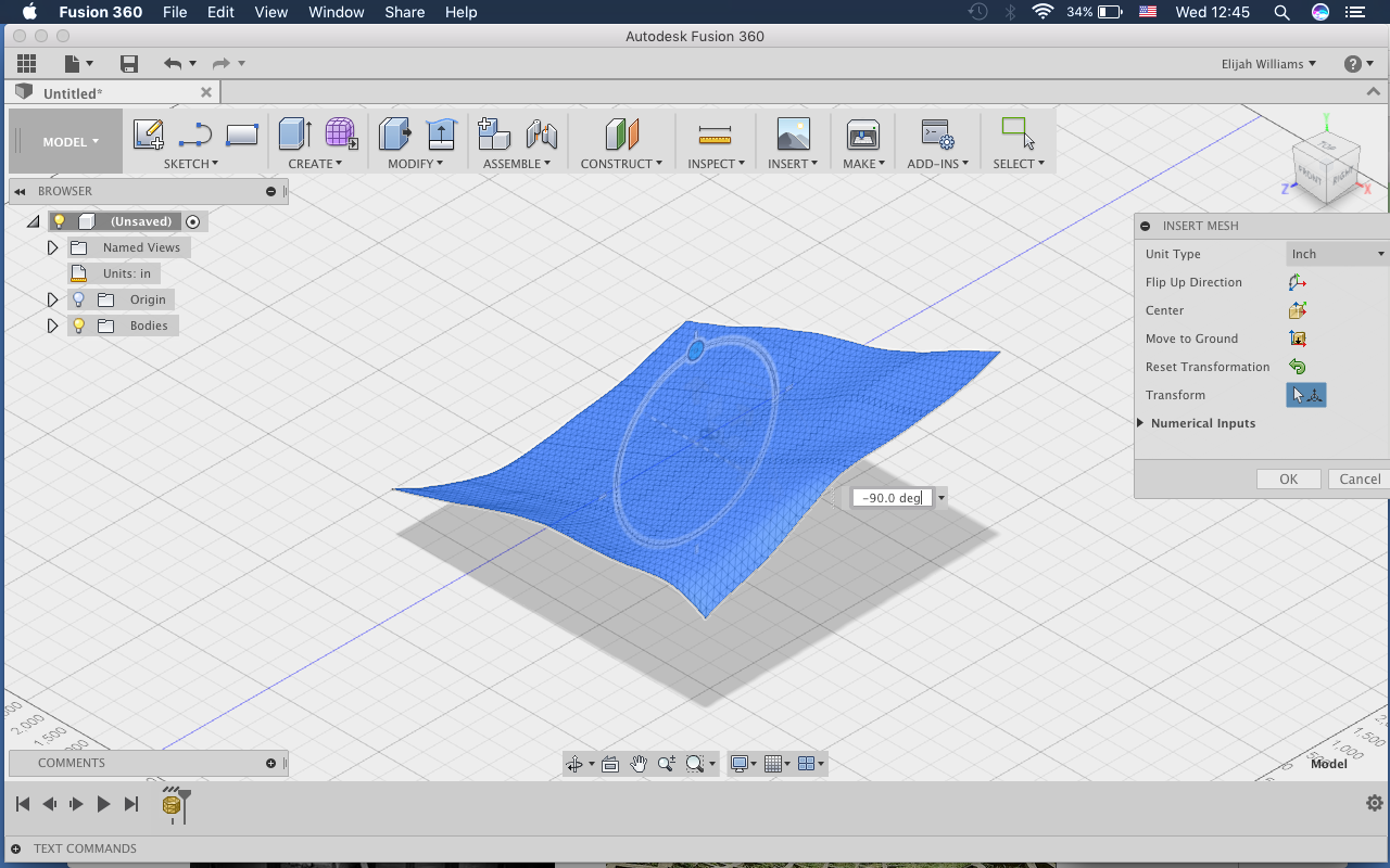
This will import your object into the center of the work-space, prompting rotation tabs which will can be easily dragged to the desired "flat" plane, or how ever you would like to orient your surface (Image 2).
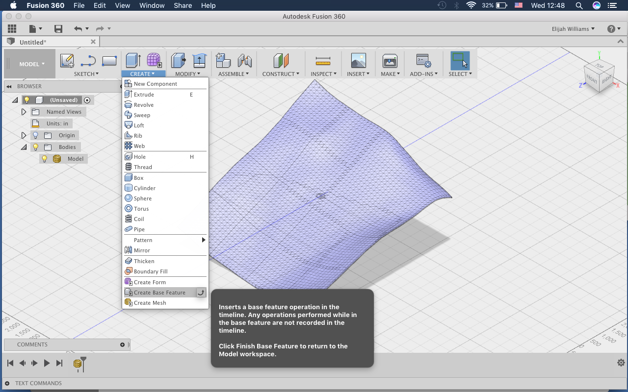
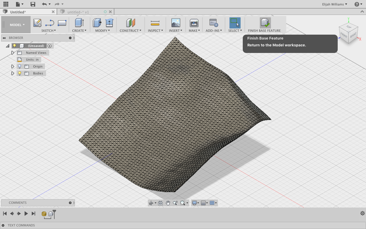
Once the object is in the correct orientation we are going to convert our mesh to BRep which will allow us to trim it with our next move.
Select the Modify tab and then search for Create Base Feature at the bottom of the list (Image 3).
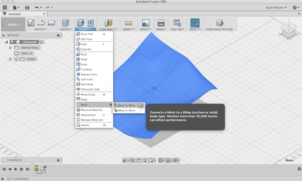
This will open up new set of tools that will appear the same except for one difference:
Under the Modify tab there will now be a Mesh option which you should select, before finally selecting mesh to BRep (Image 4).
After prompted to click OK, select the Finish Base Feature option at the right end of the tool bar.
It can be a smart choice to Reduce Your Mesh in the Create Mesh option under the Create Tab.
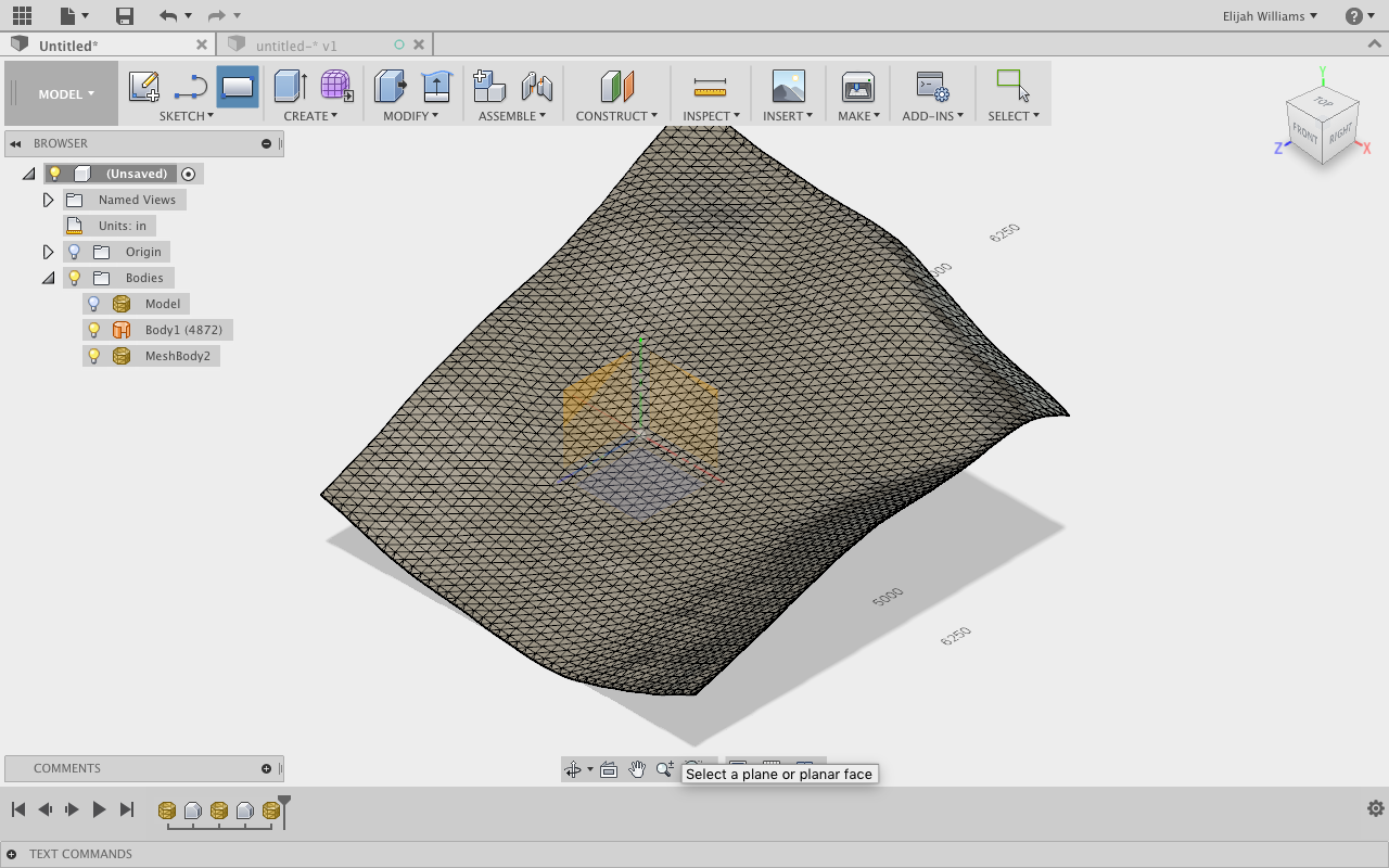
The mesh is now visible and editable as an object in Fusion 360 (Image 5).
Now your imported File is a Fusion 360 friendly object in only a few steps!
NOTE: Now we will go about creating a base for our model. From these steps on you will have to adjust your measurements based on the desired size and scale of the model you hope to create. It is very important to be in communication with both Shop techs and manufactures about restraints that your mill may have so your time will be well spent in building this file.
Creating a Base for Your Model (almost There!)
We will now begin the process of creating a base for your topographical object that you have created. Since we will be milling this file it is necessary to consider what size of stock material you have and what the limits of your machine are.
Note: In order to streamline the process I am going to scale the object after creating the base and will provide instructions on how to do so, but feel free to scale at any point.
In the upper right corner of your screen is the navigation ViewCube that will help you orient your model. If at any point your orientation gets misaligned, simply select the home logo above the ViewCube.
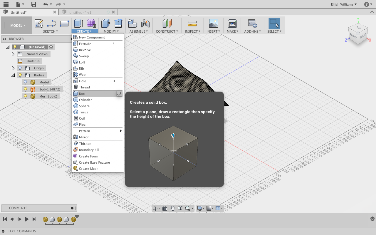
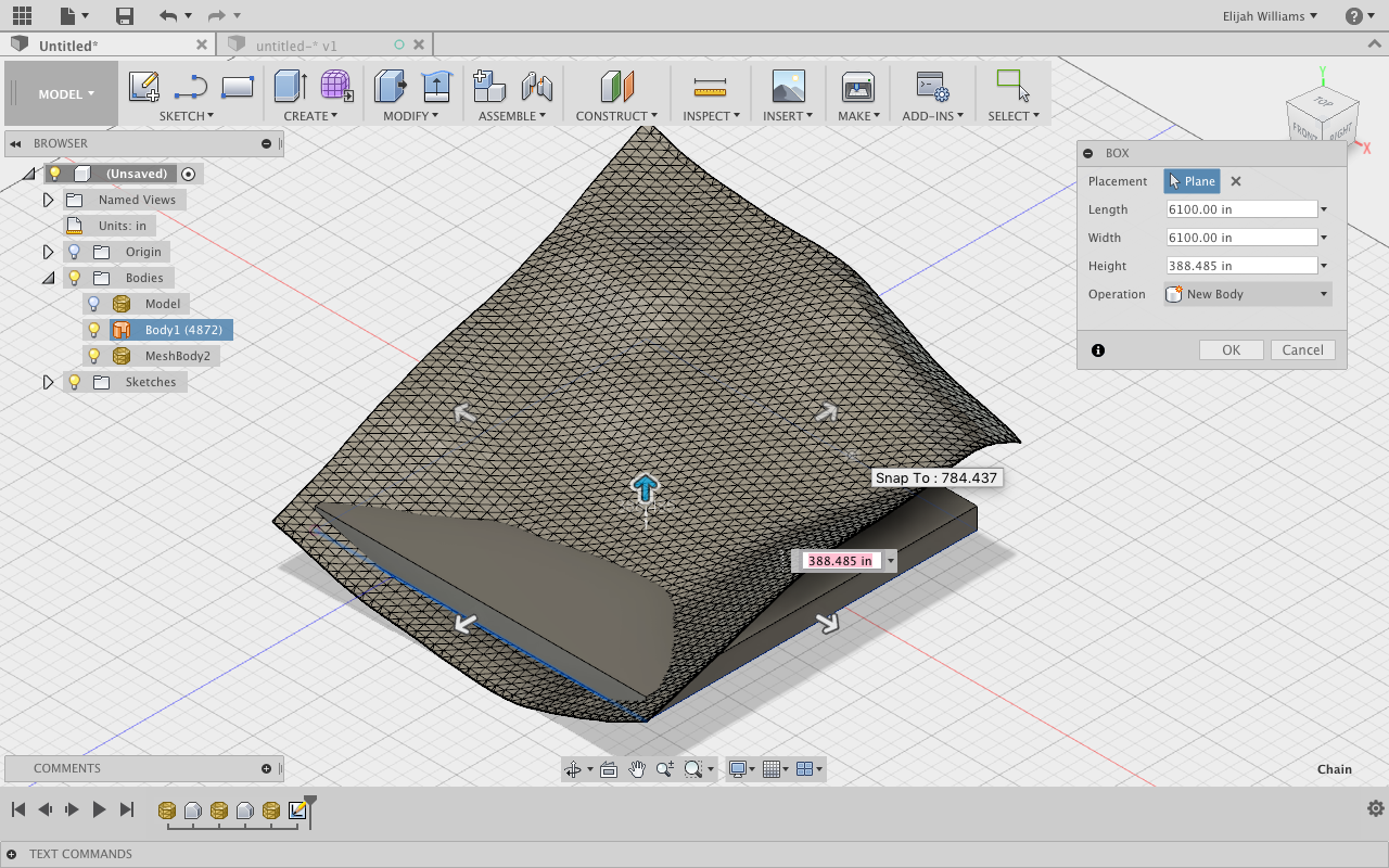
First Under the Create tab select Box. You will be prompted to select plane you wish to start your block on (Image 1).
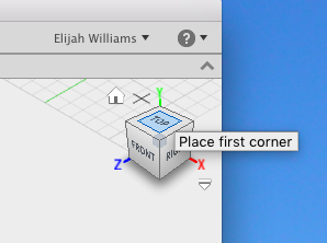
You will see that as you move your cursor around the model it will be selecting planes to build your cube. Select the XY plane (the plane directly below your mesh). It can be difficult to see but the selected square will be blue while the other two planes will be yellow. Click anywhere on the screen when the XY plane is blue to enter Sketch Mode (Image 2).
After Clicking, bring your mouse over to the ViewCube and select the top option (Image 3).
This will orient the top of the model facing towards you. Click and drag to create a 2D Rectangle that will use to create your form. With your selection, aim to capture the maximum amount of the topography, while leaving a boundary around the exterior of the cube (Image 4). When you have clicked the two sides of the rectangle press enter/ok. (Image 5)
Note: The amount you are able to select and the shape of your selection will determine the final object. Make this selection with reference to your desired output.
Optional: My form is square so I selected the largest possible square region leaving a small boarder outside of the shape.To create a square, click your first corner and drag to see the maximum measurements. Enter the shorter measurement, press tab, enter the same number again, press tab and then enter.
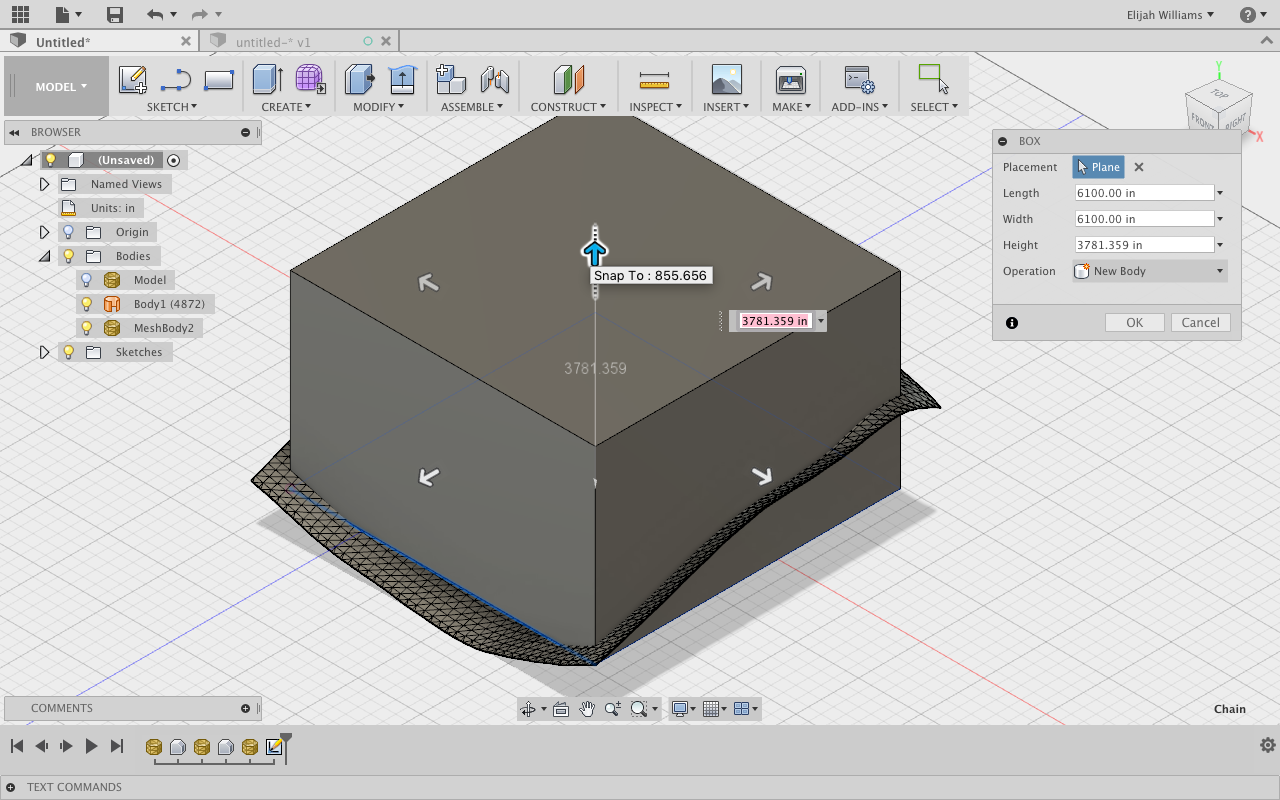
Move your cursor up to the Viewcube and select the home icon. You will be prompted to drag your cube up to the desired height (Image 6).
Make sure the new height completely intersects the object plane we imported. This is key for the next step.
Preparing the Final Form ( Final Step)
Now is a great time to scale the whole object to prepare it.
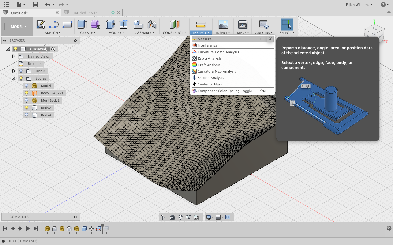
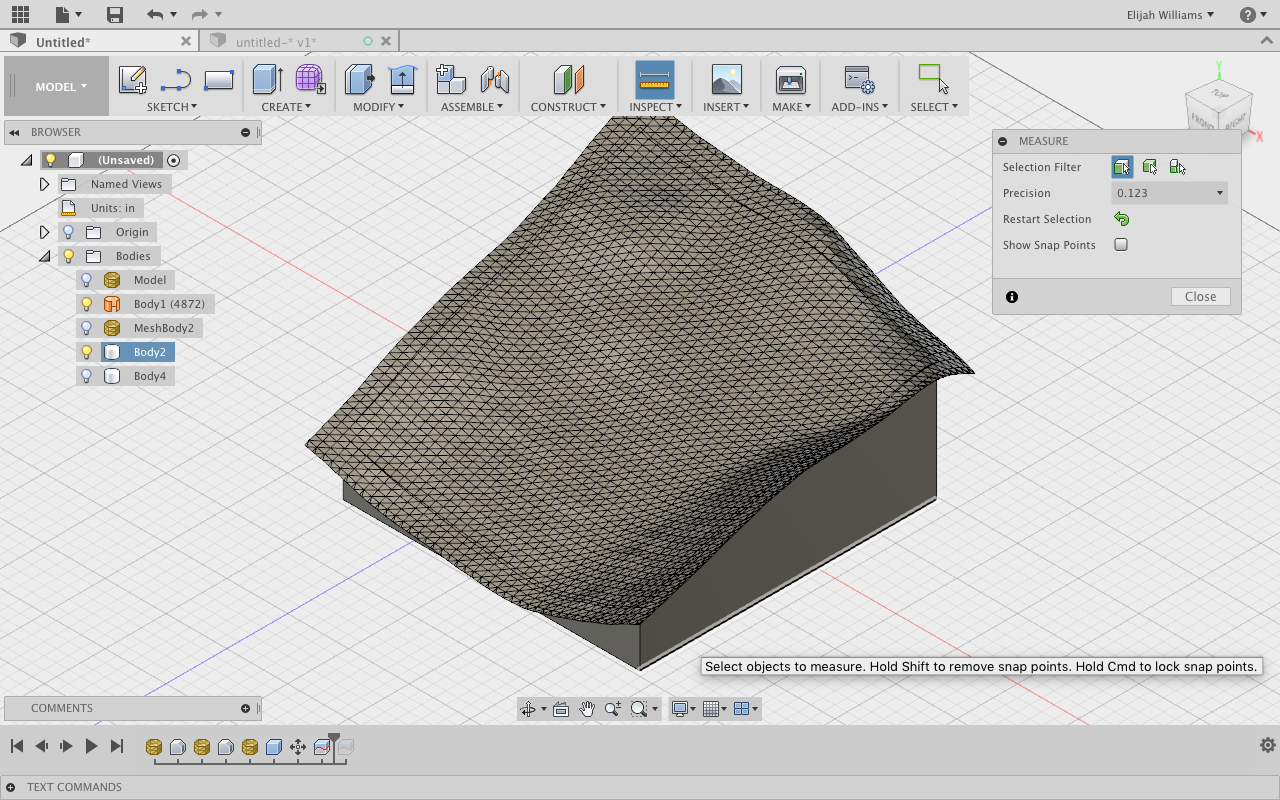
First, select the Inspect tab and then Measure (Image 1). Select the bottom edge of the cube and find the readout in the bottom right of the screen (Image 2/3).
In my case I have my readout in Inches, 6100 to be exact.
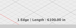
To calculate the desired scale factor, divide you desired length by the given length.
Desired Length/Current length = Scale Factor = 8/6100
so my scale factor is 0.001311.
Select the Modify tab and then Scale. Select both the objects to scale and input your scale factor (Image 4).
Measure again to check that your base is your desired length.
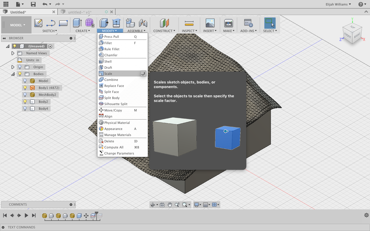
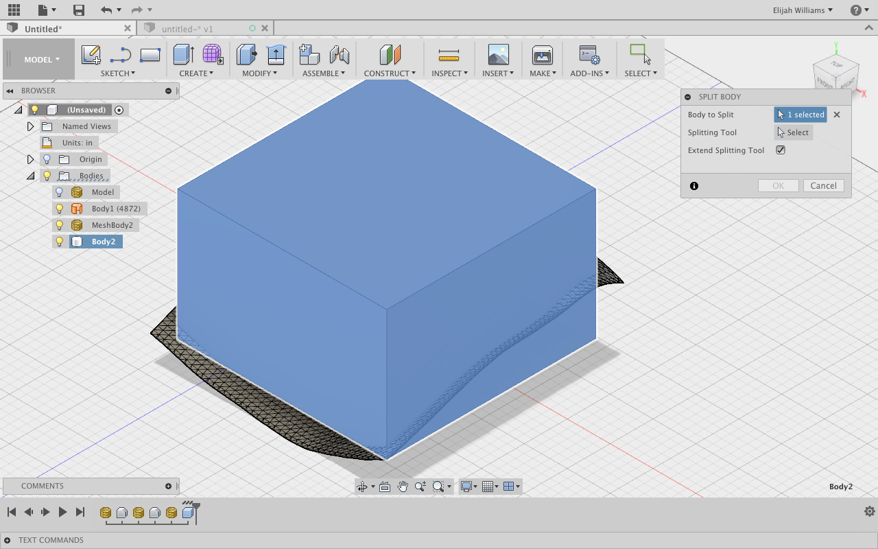
With our cube completely intersecting our plane we must now trim the cube to prepare it to be moved to the CAM work space.
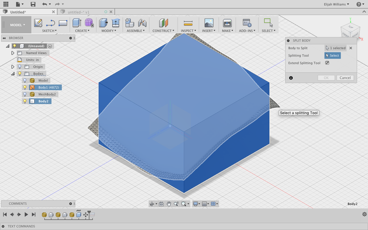
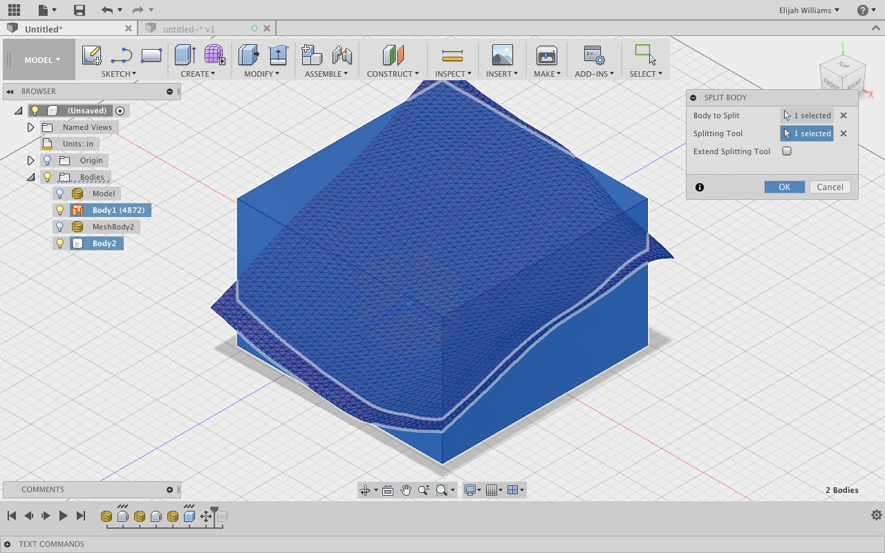
Under the Modify tap select Split Body. This will bring up a multi-selection menu. Select the cube as the body to split and the mesh as the splitting object (Image 5-7).
Under the Bodies tab along the left side of the screen, toggle
through the body options until the top half of the cube is visible as well as the mesh (Image 8).
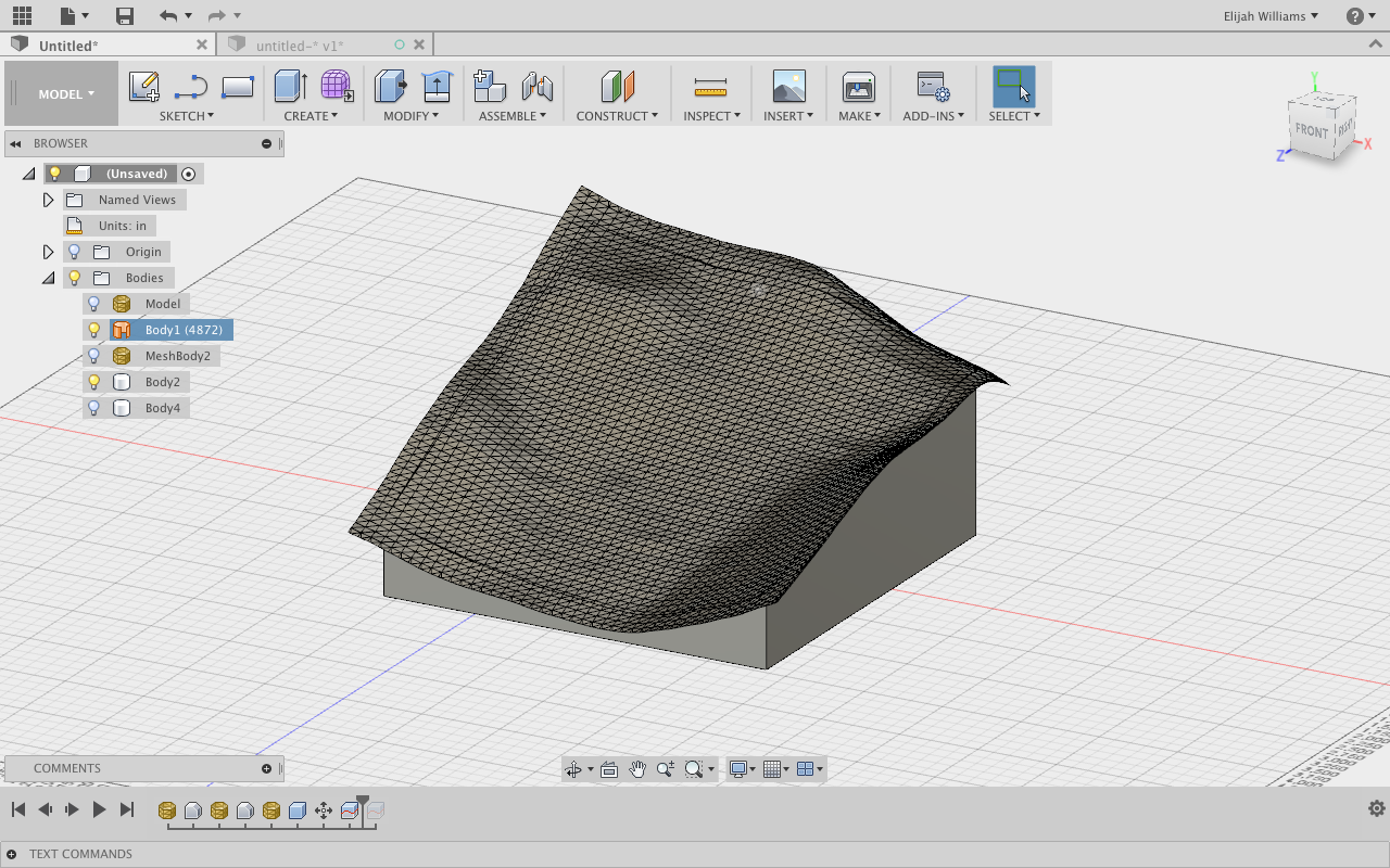
You are finished! Looks great! (Image 9)
With our cube completely intersecting our plane we must now trim the cube to prepare it to be moved to the CAM work space.
Now lets set up a very general CAM file so you can work with your shops techs to get it the job done as you desire.
Setting Up a Cam Operation to Rough Topographical Model
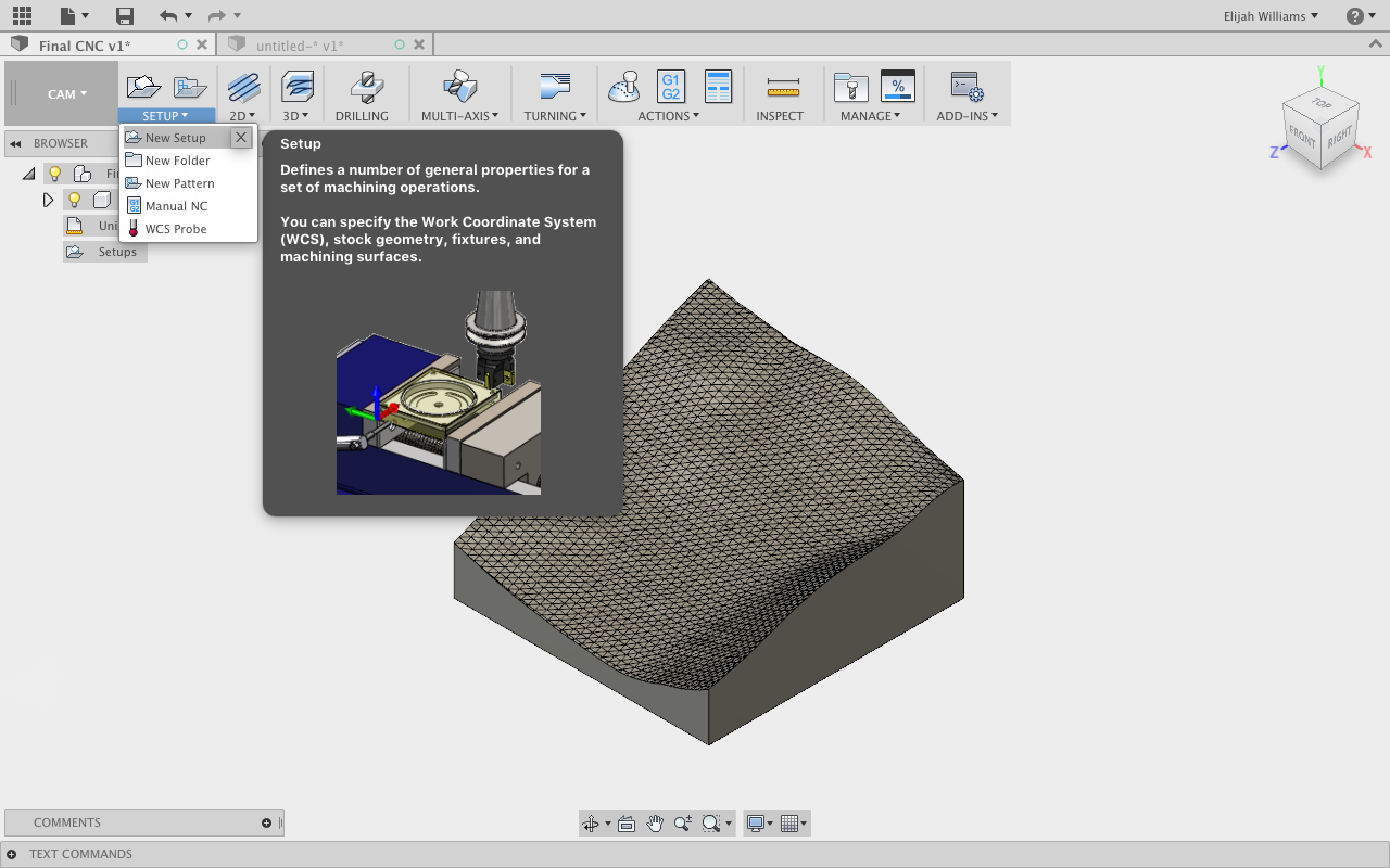
Our first move is switching from Model to Cam work space. This is done using the large tab in the upper left corner of the Fusion 360 window. Once you are in the Cam work space, select the Setup tab and then New Set Up (Image 1).
WARNING: While these commands are fairly universal every step of the CAM process should be checked by someone with experience with the machine and the processes involved. This is relevant in particular for every step following this warning.
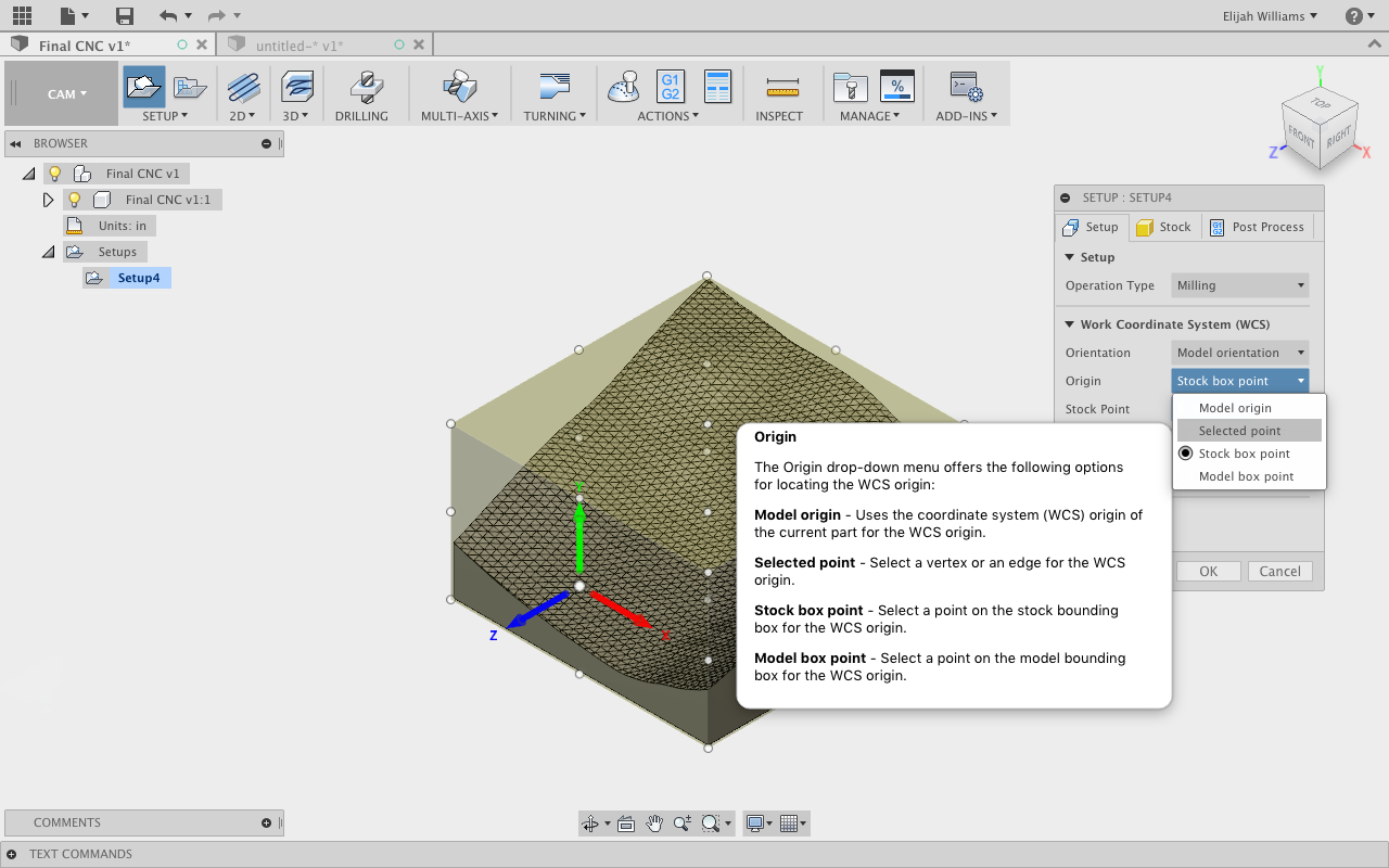
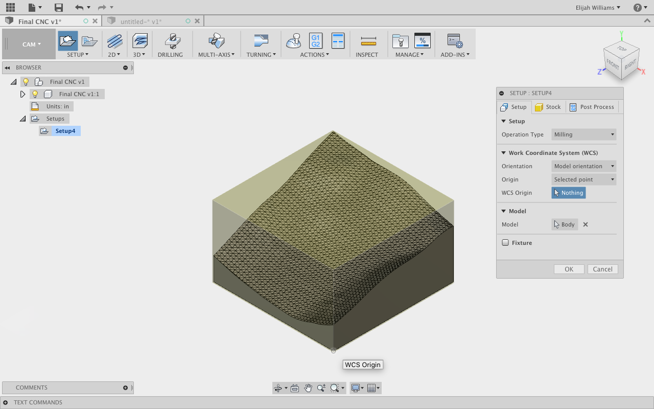
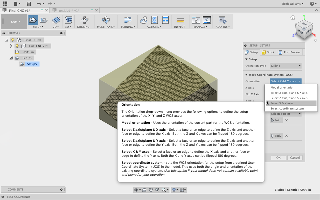
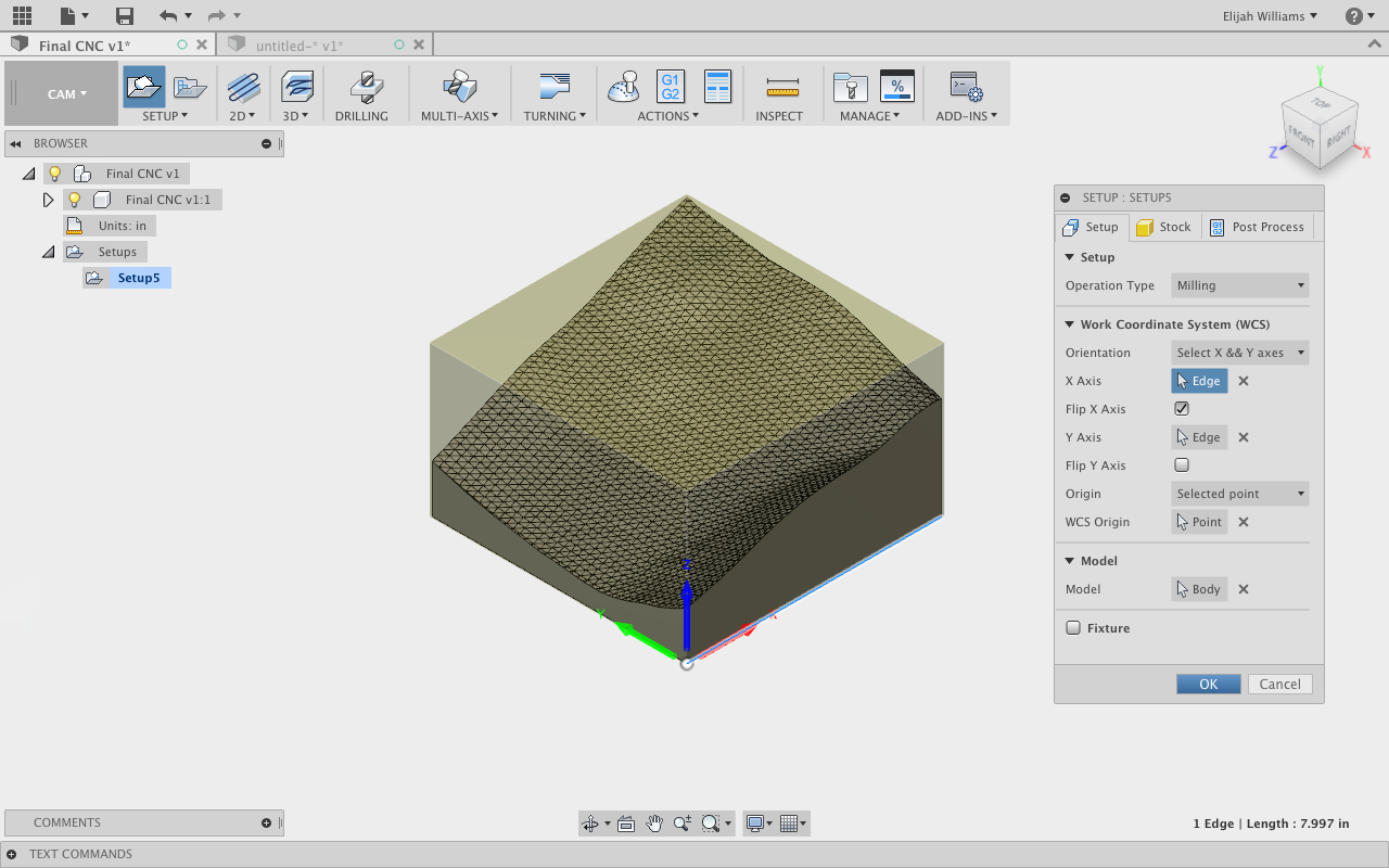
The first thing we will do in New Set Up is select our Origin. Under the Origin tab select the Selected Point. With the home icon selected from the ViewCube select the bottom corner closest to you (Image 2/3).
Now select the tab directly above it, titled Orientation (Image 4). There are many ways to go about orienting yourself correctly but an easy option is to choose Select X & Y axes, pick the desired X and Y axis and the Z axis will auto correct to the desired vertical component. You will need to Flip X before the Orientation will match the one pictured above (Image 5).
Our orientation set correctly we can move to building our first tool path.
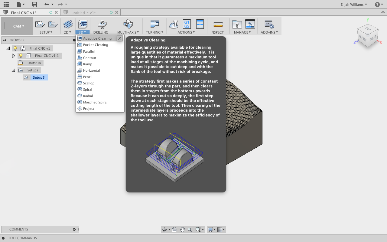
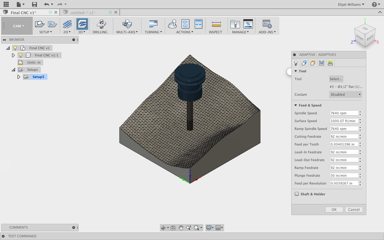
Under the 3D tab select Adaptive Clearing. One of the benefits of Fusion 360 is its CAM options and Adaptive tool paths which combine what would typically be multiple tool paths into one extremely effective tool path (Image 6).
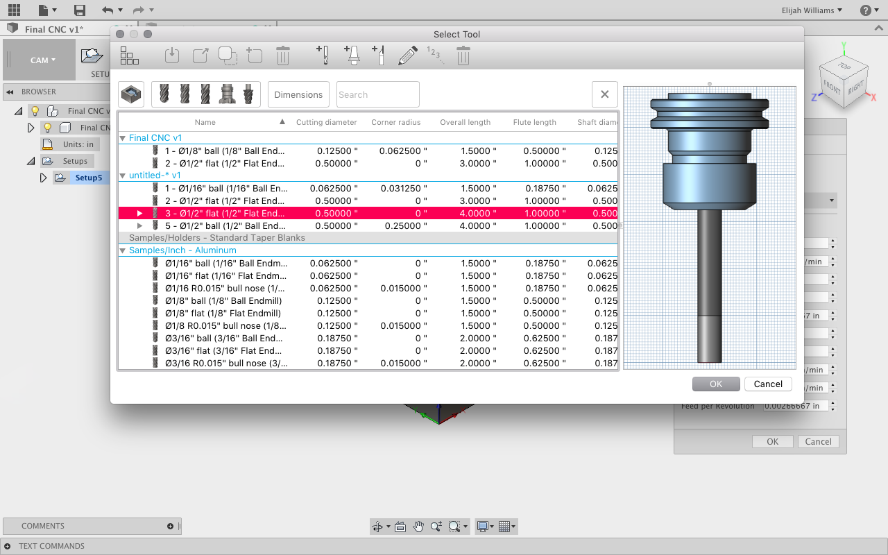
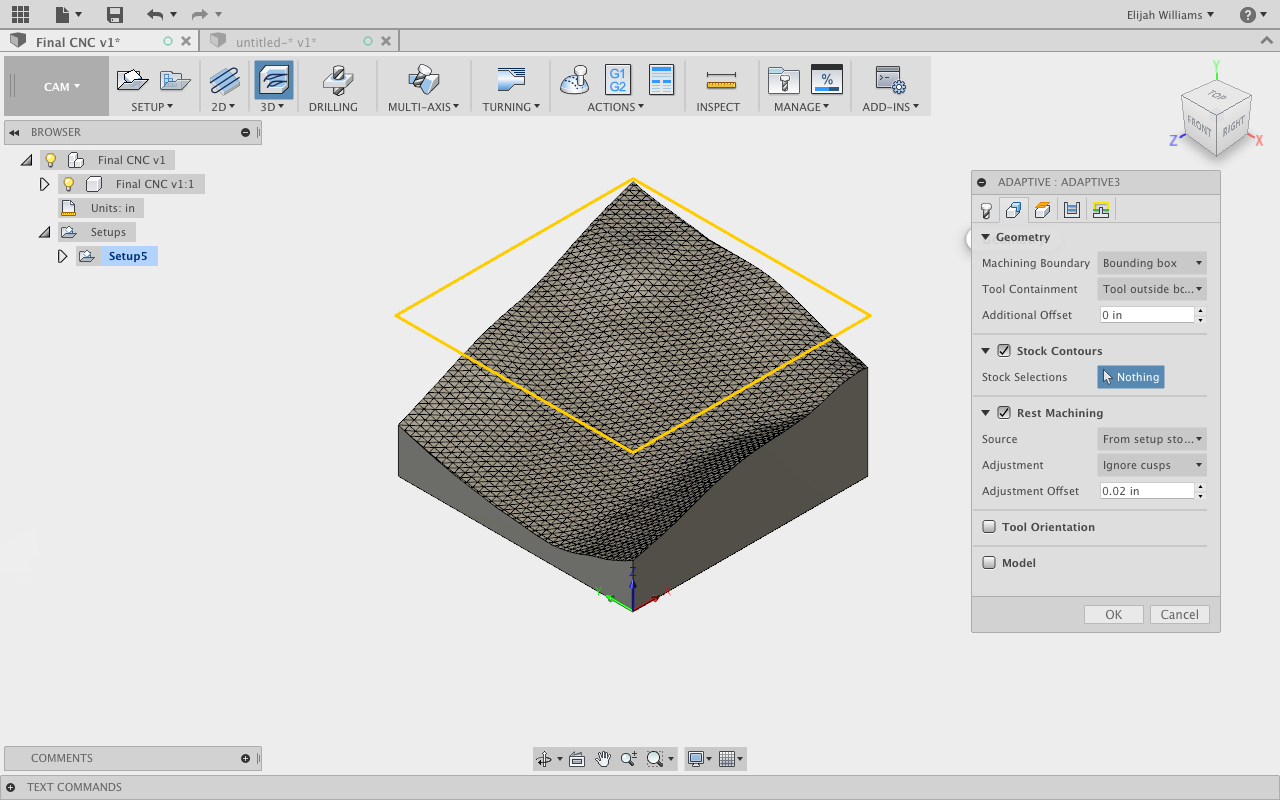
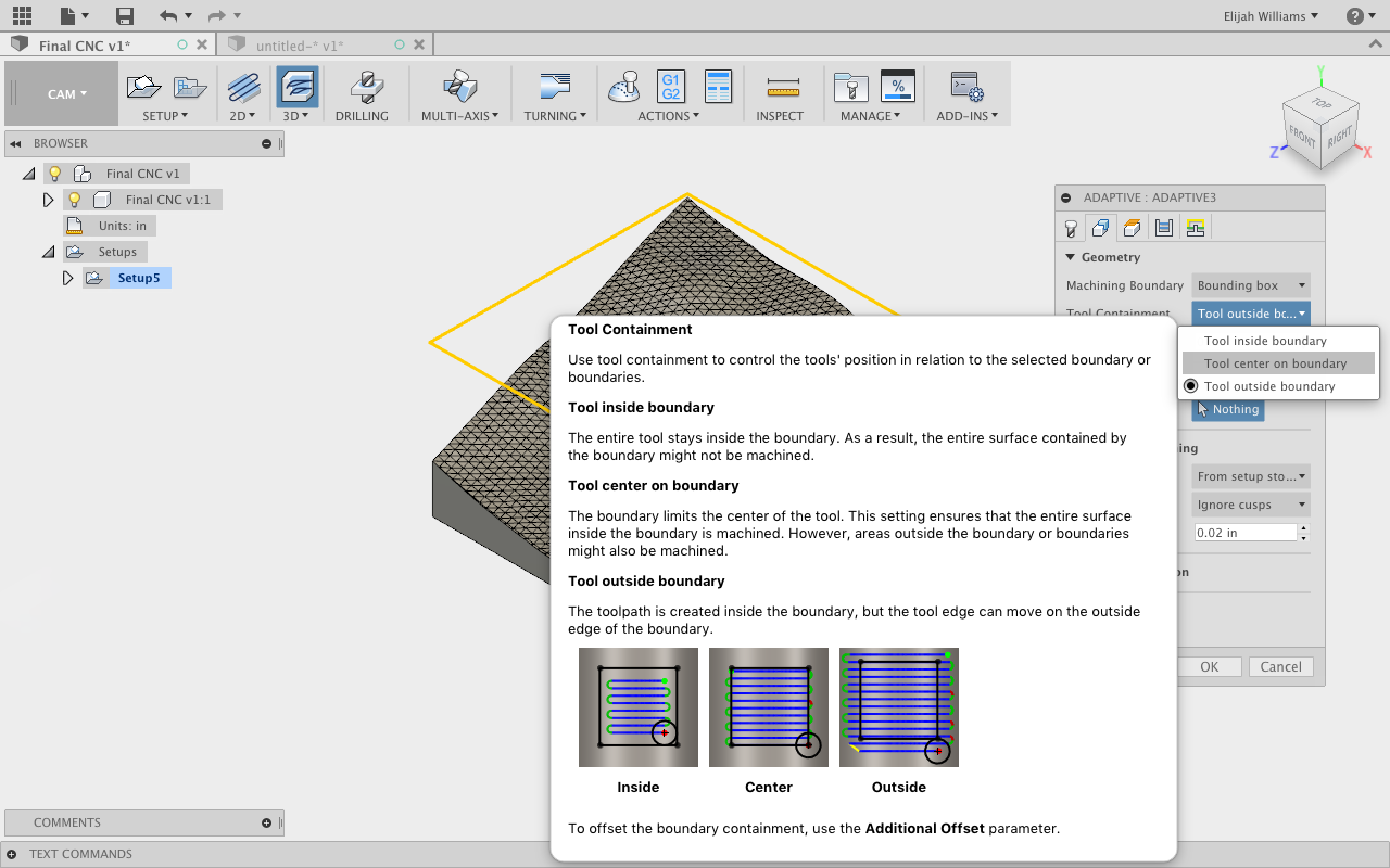
Opening Adaptive Clearing will prompt a new toolbar that is universal across all commands. First we will select our Tool from the tool menu (Image 7/8). Once our tool is selected we can switch to the Geometry section of the command (Image 9). We will change Tool Containment, moving it from Tool Outside on Boundary to Tool Inside on Boundary. This tells the program how to orient the tools tool paths (Image 10).
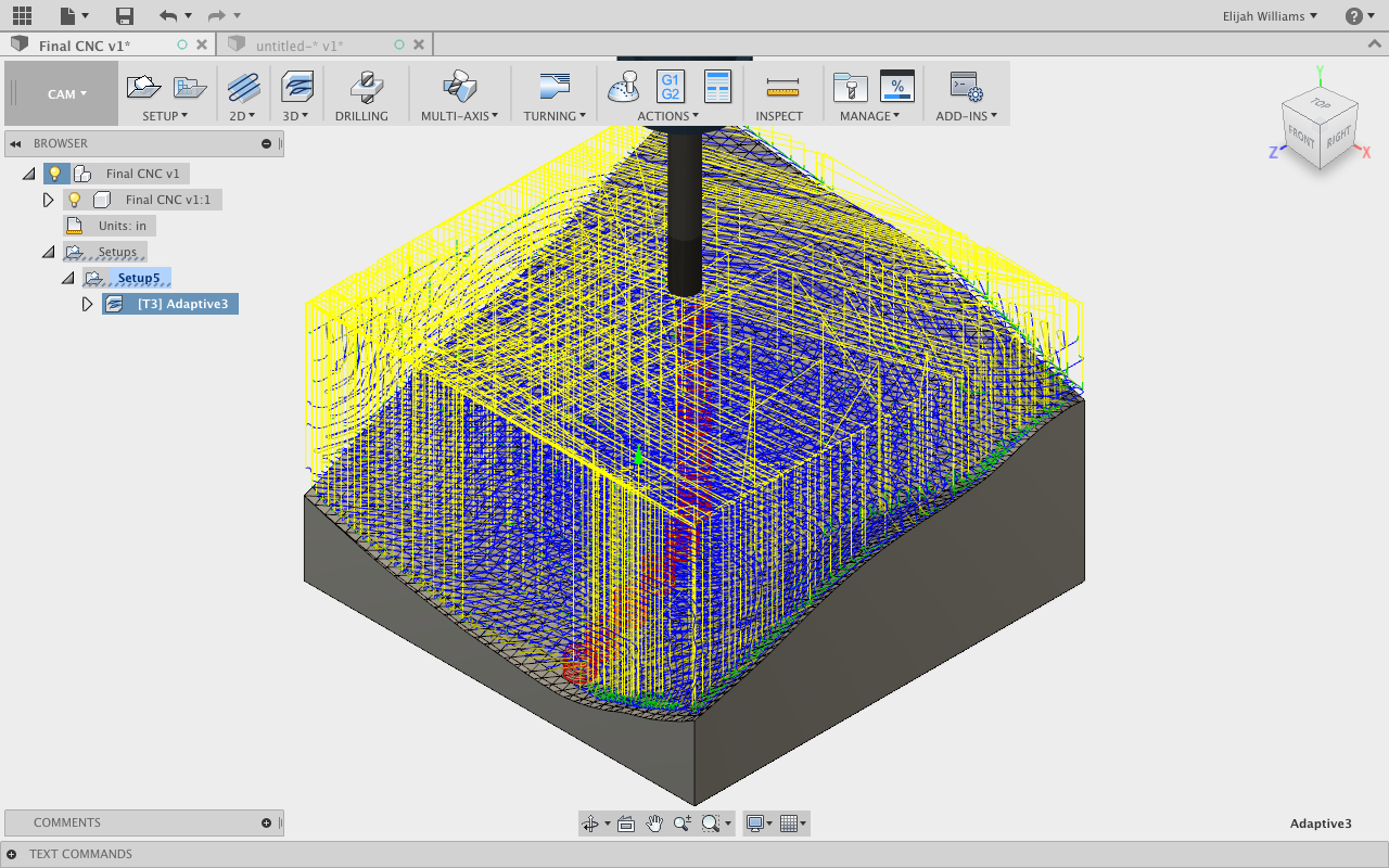
By pressing OK we will prompt the creation of the tool path in the work space. We an Choose the Simulate tab watch our tool create our cuts (Image 11).
To reiterate, this is a preliminary check Tool path, and includes none of the Tool Speeds which are a key component to the success of any CNC job. These speeds and feeds are dependent on the material and most importantly, the machine which you are cutting on. This would be a good stage to take this file to a Shop Tech and have them look over your file and help you set the speeds and feeds.
And the Final Step....
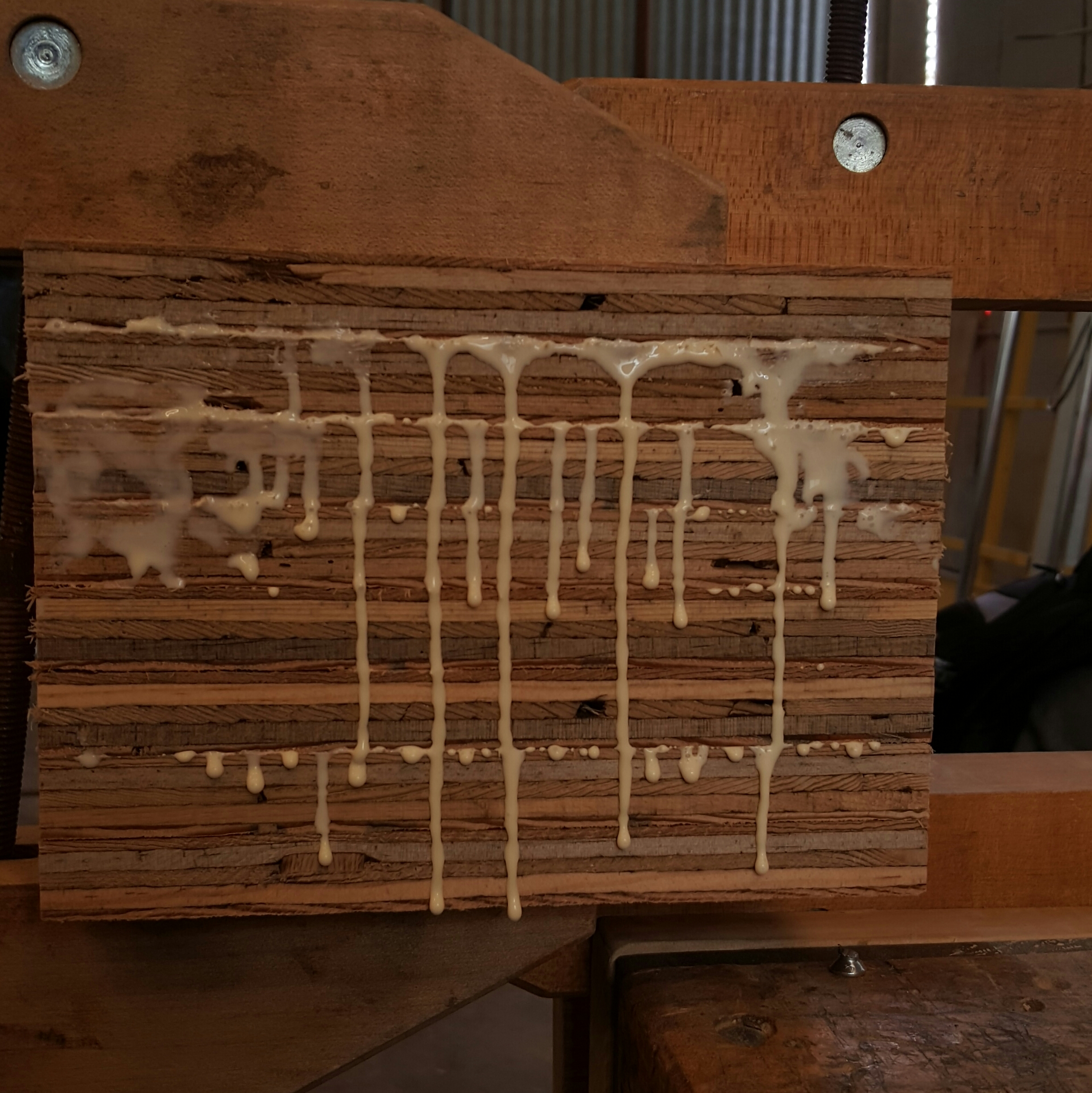

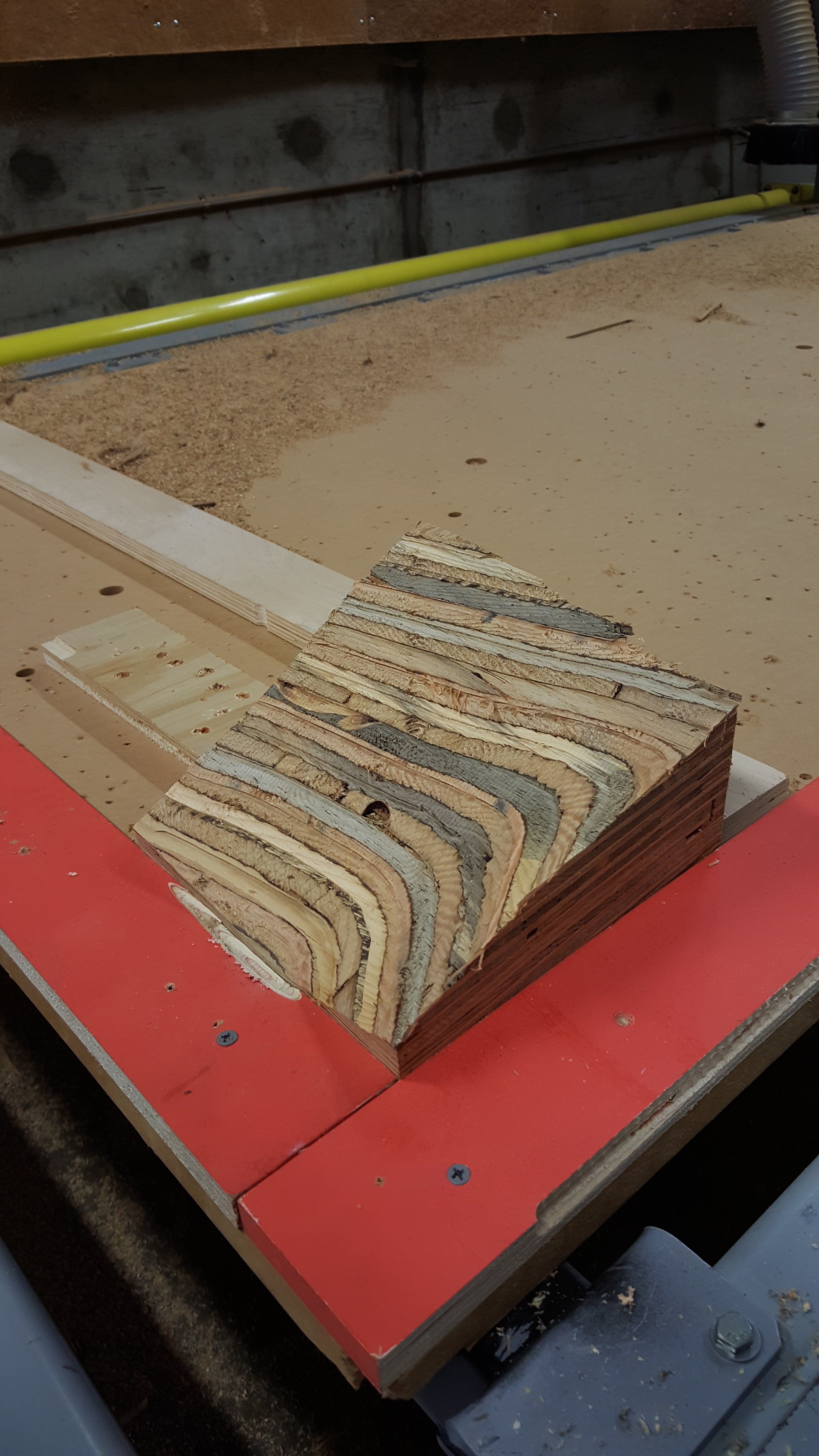
Glued Plywood, nothing a little water and sand paper can't fix (Image 1).
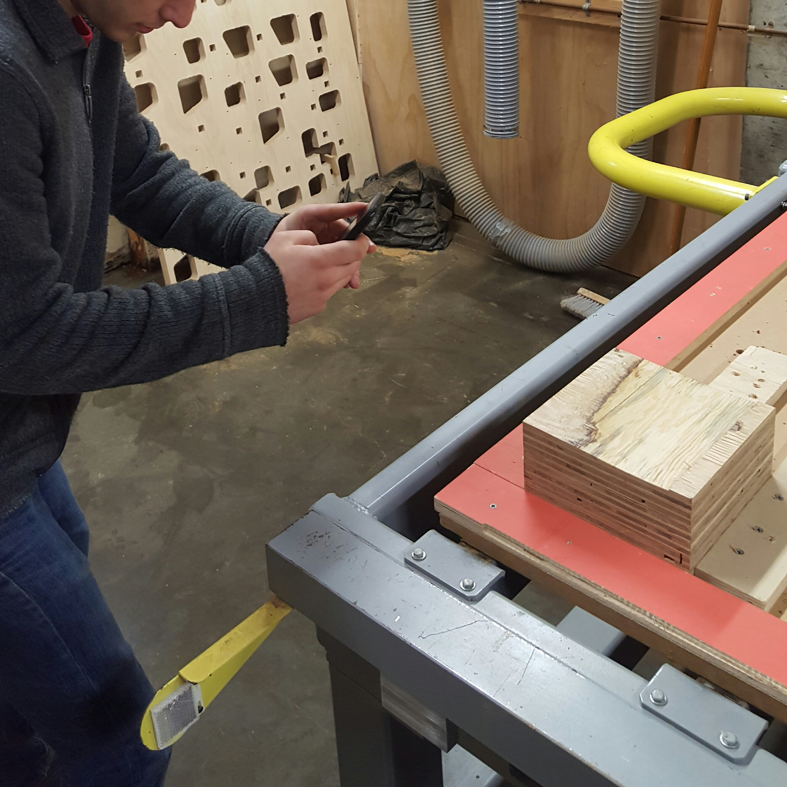
Completely needed pre-cut photos and set up (Image 2).
And the finished product!
Plywood may be a basic material but milling reveals some fitting lines for a topographical model, their sizes change based on the slope of the terrain.
To Restate Our Process:
We first exported a Topographical Mesh from Sketchup and then imported it to Fusion 360.
We turned it into a object, scaled it and built a base for it using the split body command.
We then brought this shape that we made into the CAM work space and designed a test tool path.
Thanks for reading! Have fun and be safe!