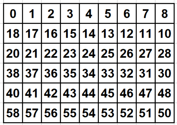
Puzzle Clock - Color Coded
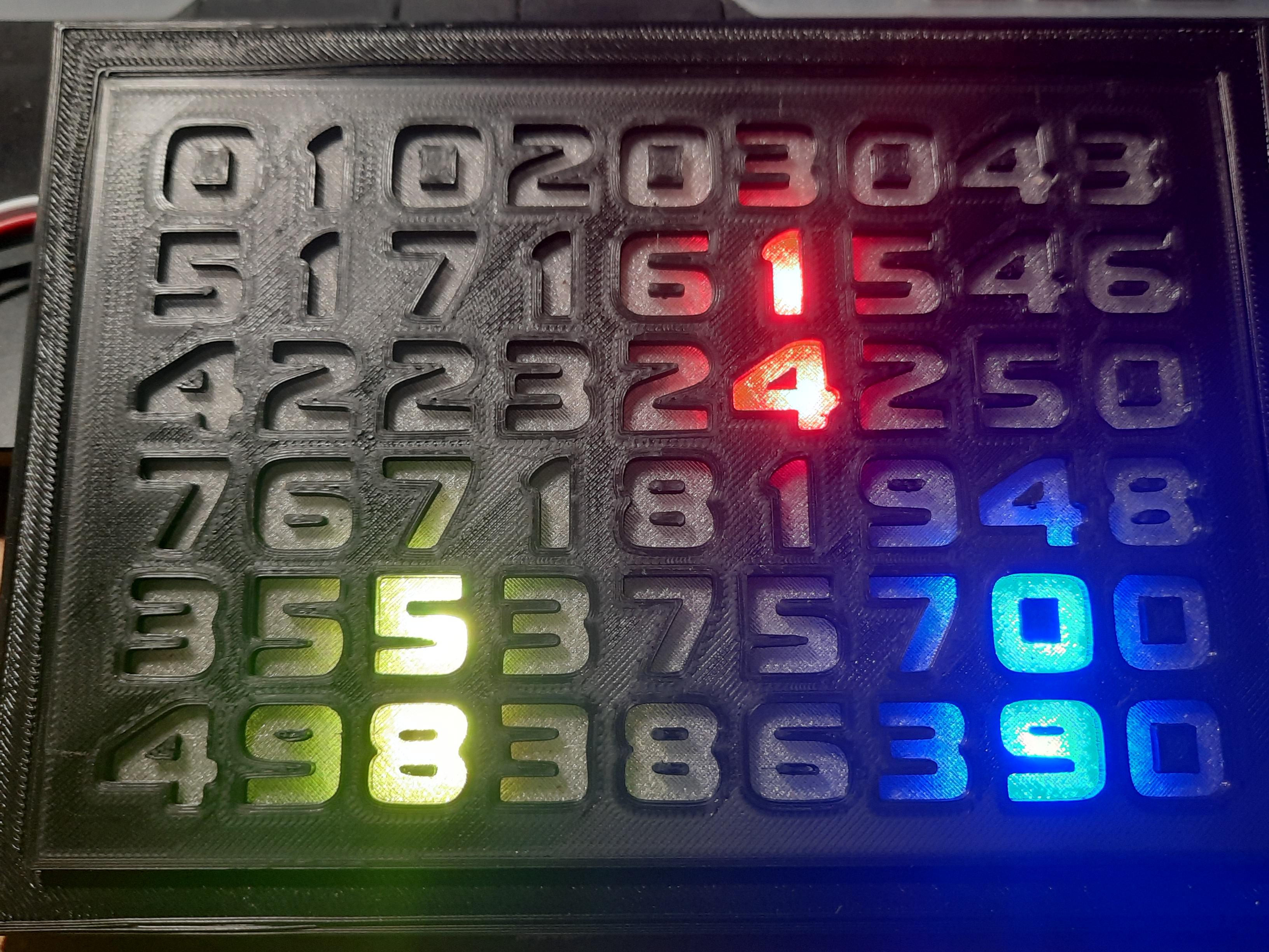
Enjoy this seemingly random arrangement of numbers that is actually a clock. My personal challenge was to make the most compact arrangement of numbers that could show all values from 00 to 60. Values are used both horizontally and vertically. A time will be a combination of two horizontal and/or vertical cell elements. Sometimes individual cells are used for different clock values, and here's where the color coding comes in.
Here are the color codes:
Hours - blue
Minutes - red
Seconds - yellow
But what happens when the same cell is used for two different time elements? The colors are combined!
If the hour and minute cell is the same, the blue and red combine to make purple.
If the hour and second cell is the same, the blue and yellow combine to make green.
If the minute and second cell is the same, the red and yellow combine to make orange.
If all the cells for the time are the same (say, at 10:10:10), all colors combine to make a dazzling white!
Downloads
Supplies

3D printer or access to print files
PLA filament (or type of your choice). Black (color optional) for frame, transparent for background. Adding a sheet of white paper to size will diffuse the light to a nice level if desired.)
Print files for frame and base
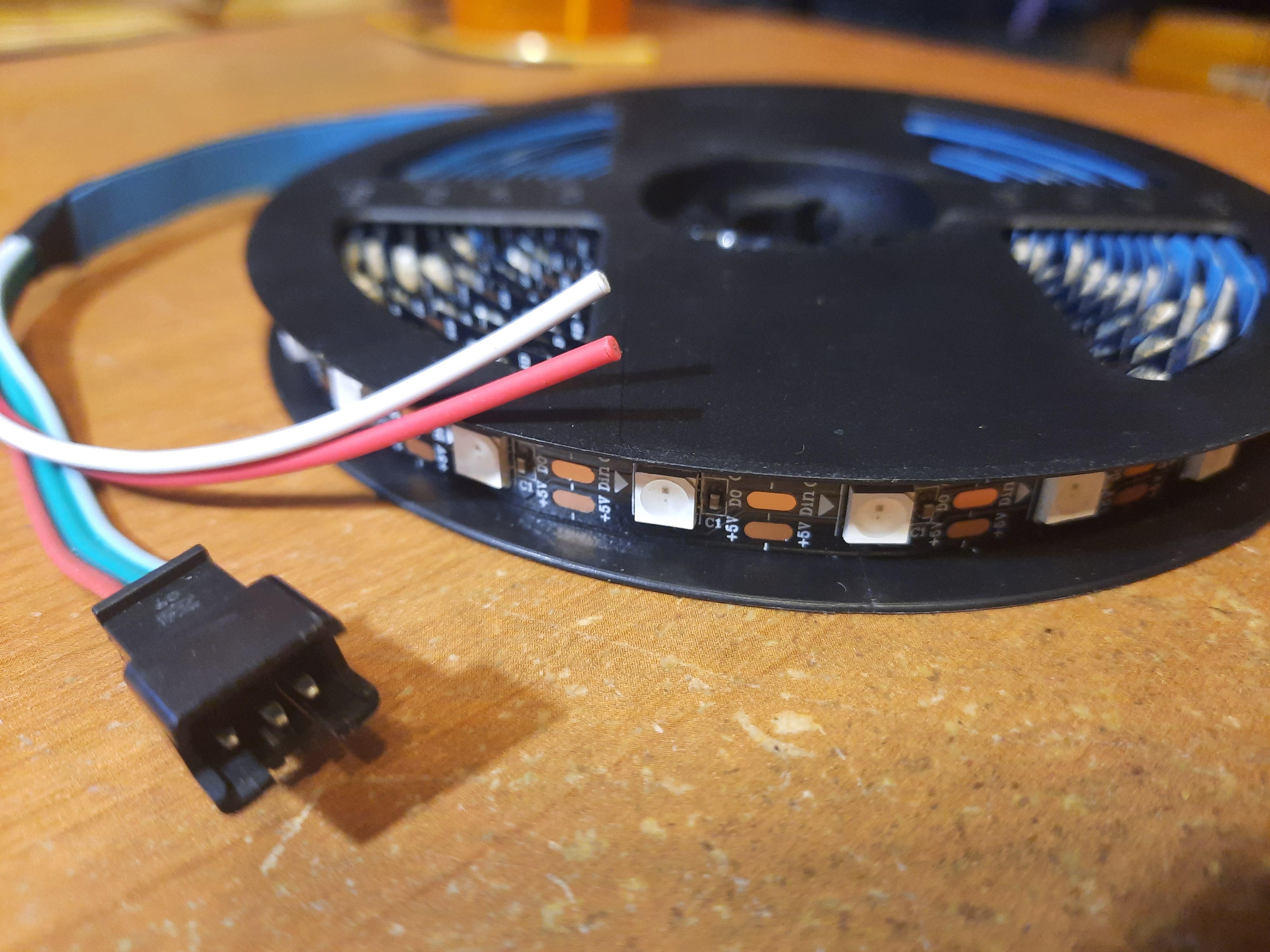
WS2812b programmable, cuttable RGB LED strip with at least 60 LEDs
LED strip placement guide
Tape for securing the LED strip. I prefer gaffer's tape because it's cloth and not gummy like duct tape.
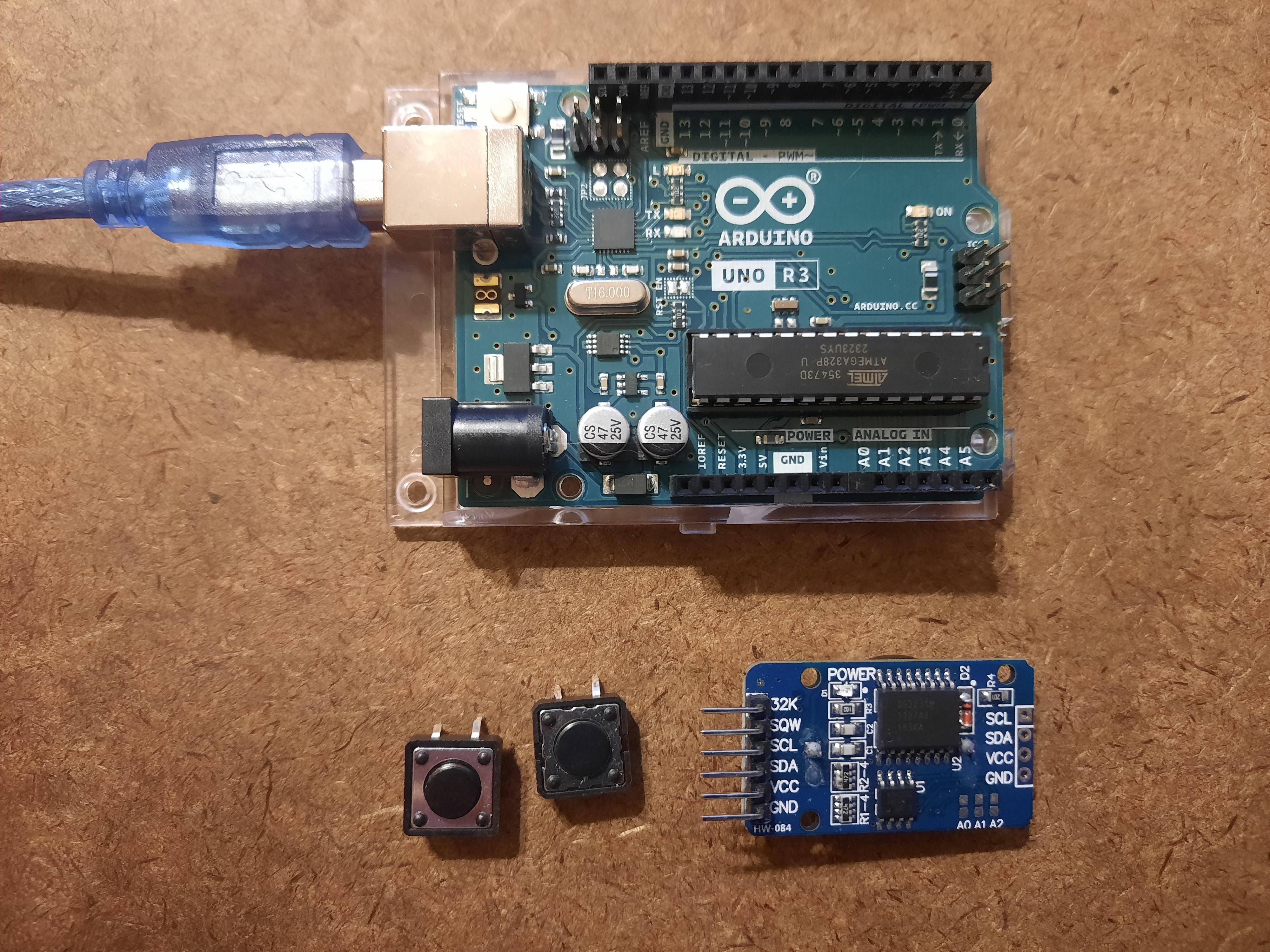
Arduino Uno (Note: this is the only one I've been able to get it to work on. Not the Leonardo, Nano, or Elegoo Uno.)
.ino files (The DS3231.h and others are included because I had a hard time finding the right libraries among the dozens available. These work with the Arduino Uno.)
Arduino editing method
DS3231 or HW-084 Real Time Clock module
CR2032 battery
Jumper wires
Breadboard (optional)
USB power plugin
Momentary pushbuttons (2)
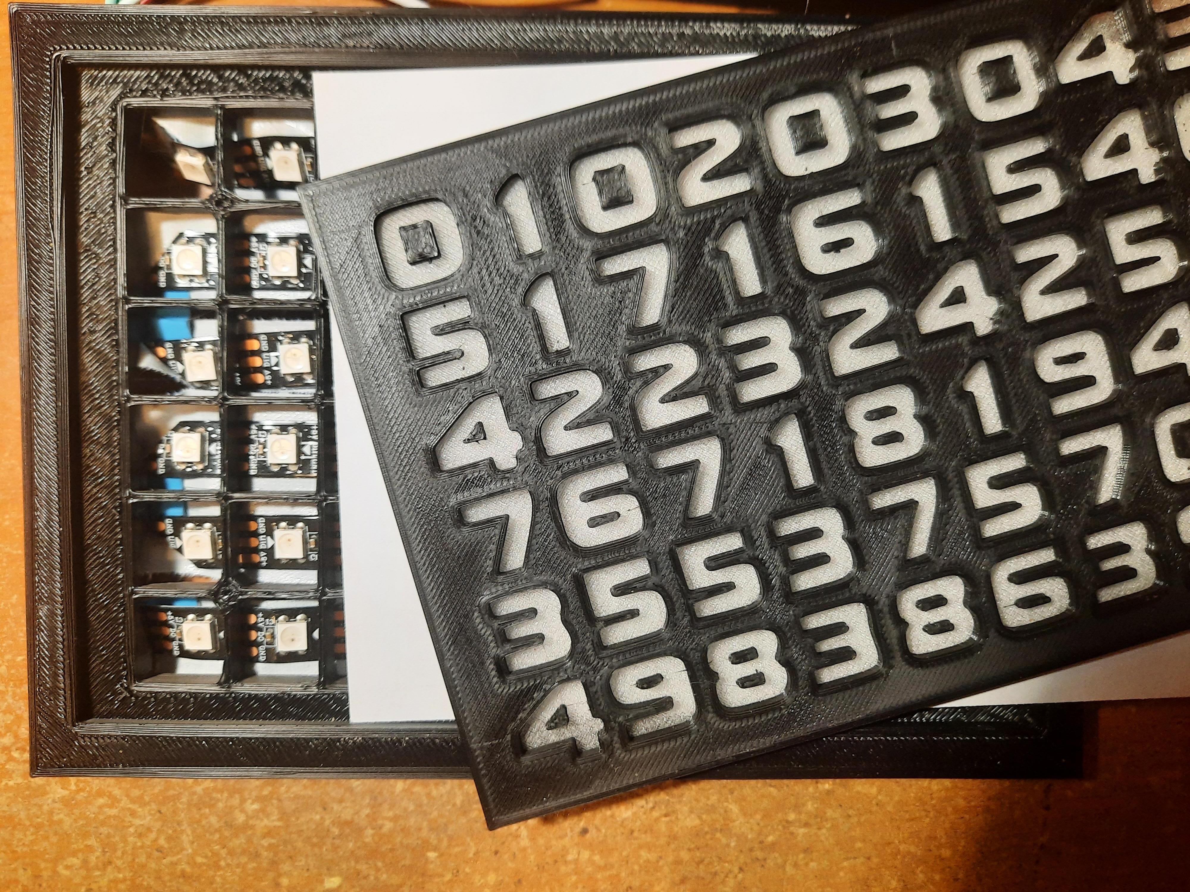
Print the Frame Parts and Display
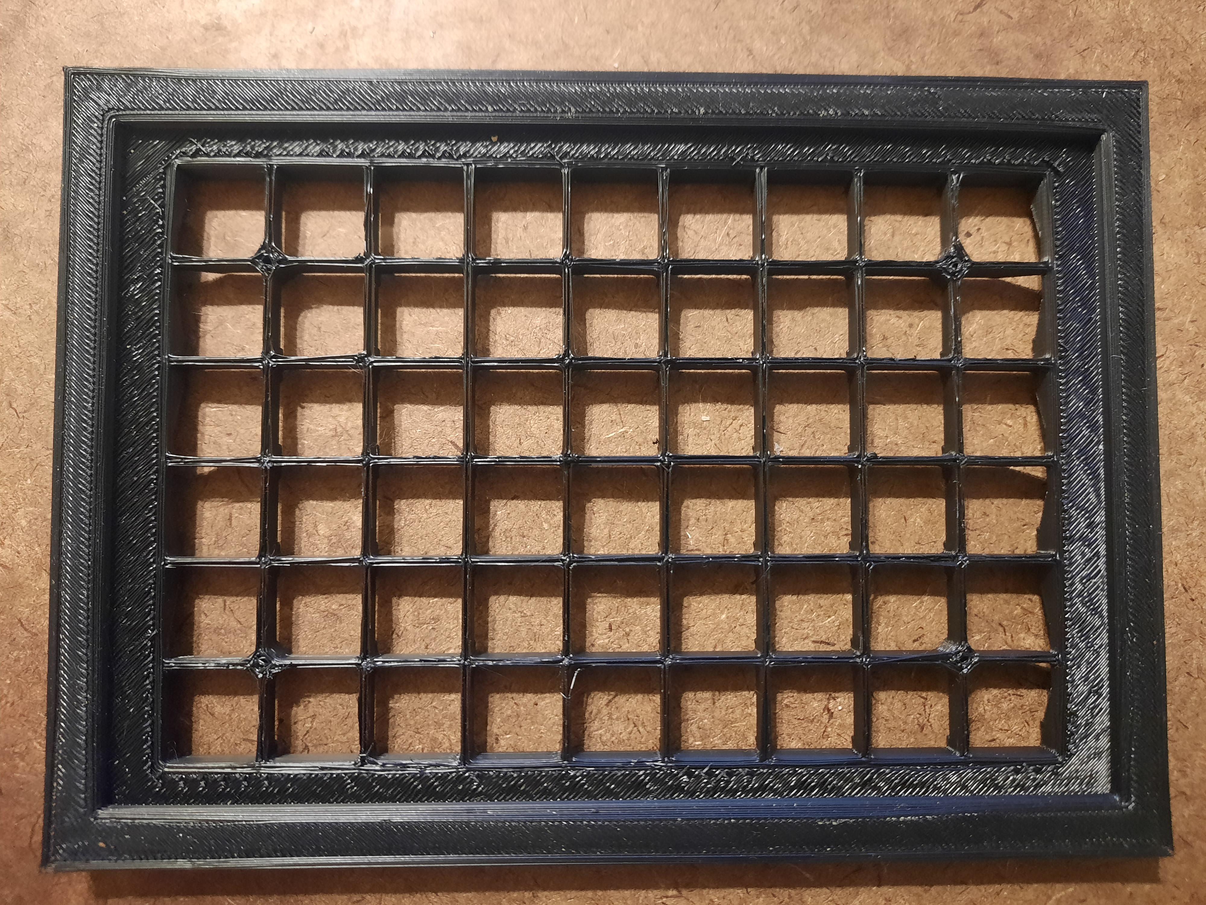
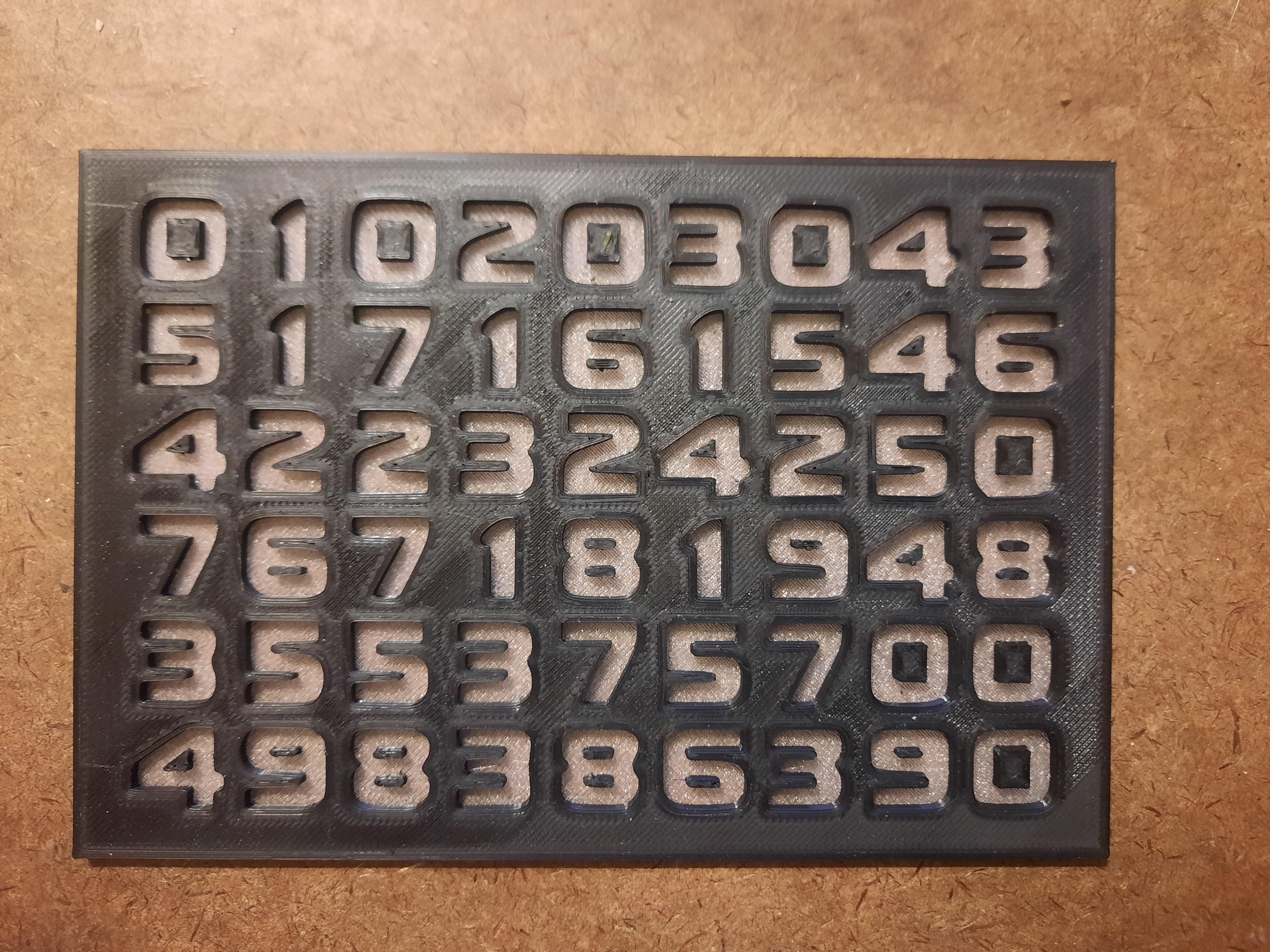

The frame is in four parts -- the 2-part base, the grid, and the display sheet. The display sheet (with the numbers) is designed to print in two different-colored levels, the first one being made with transparent filament. The second-level (black) display numbers have to be printed on top of the transparent level because of the loose center elements in numbers 0, 4, 6, 8, and 9. Follow your printer instructions for changing filament mid-print.
(Alternately, you could create the number grid with a locked-in font, such as a stencil that has no "loose" elements. Then you could use the paper diffuser and not need a transparent level.)
Cut the LED Strip and Attach to Grid
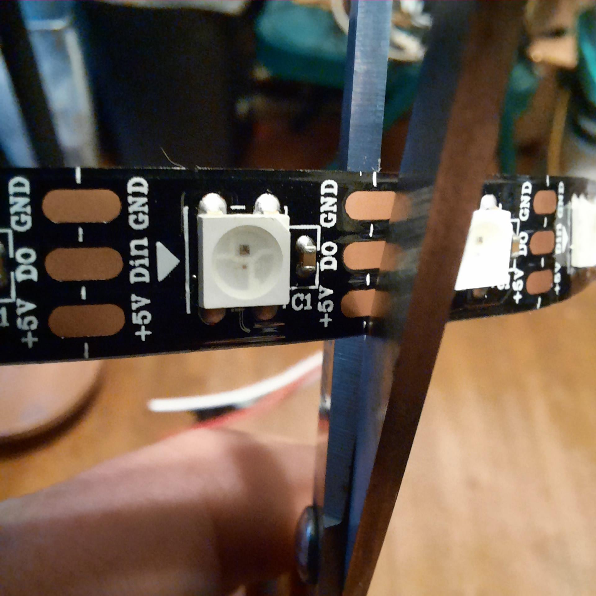
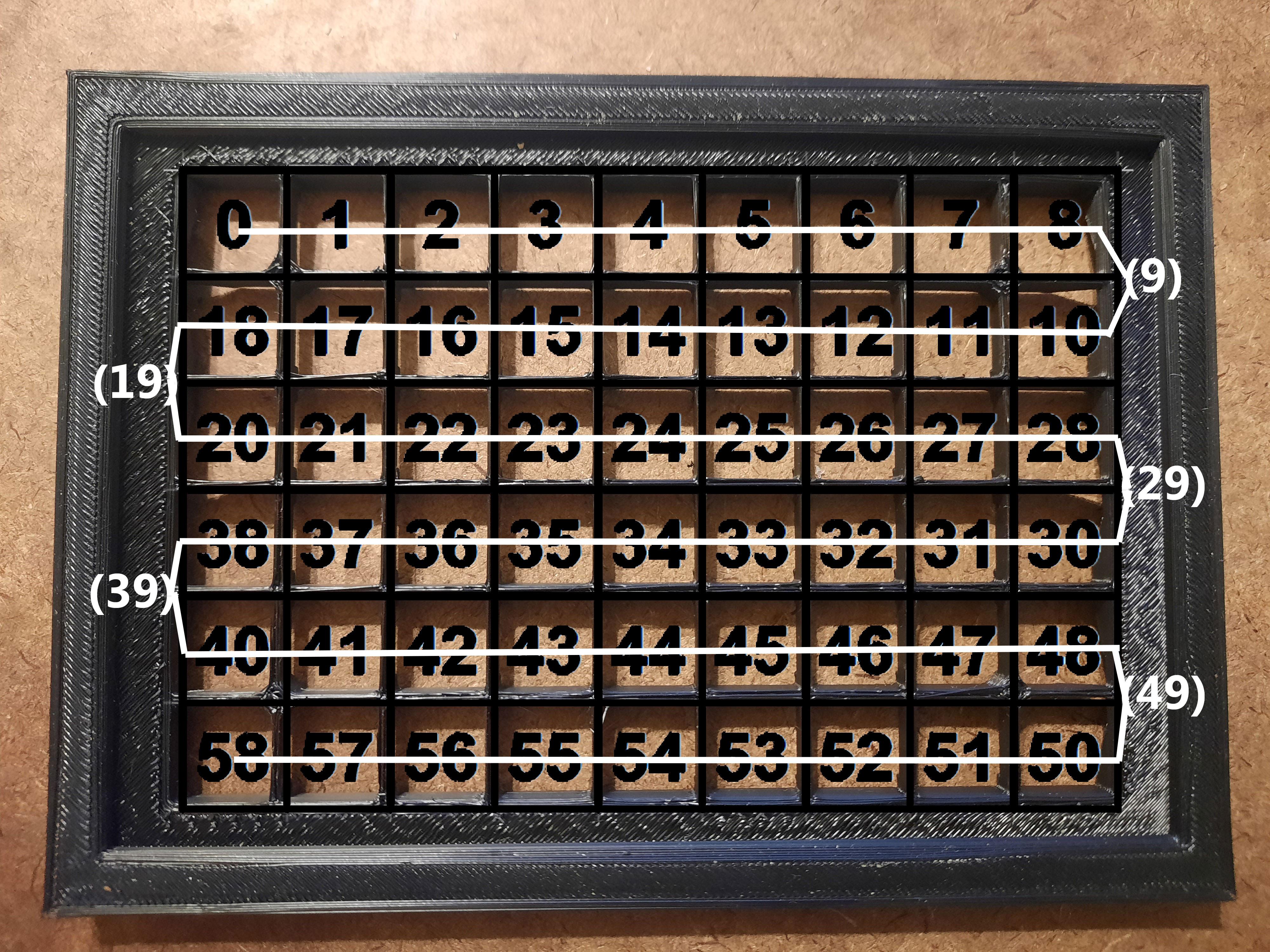
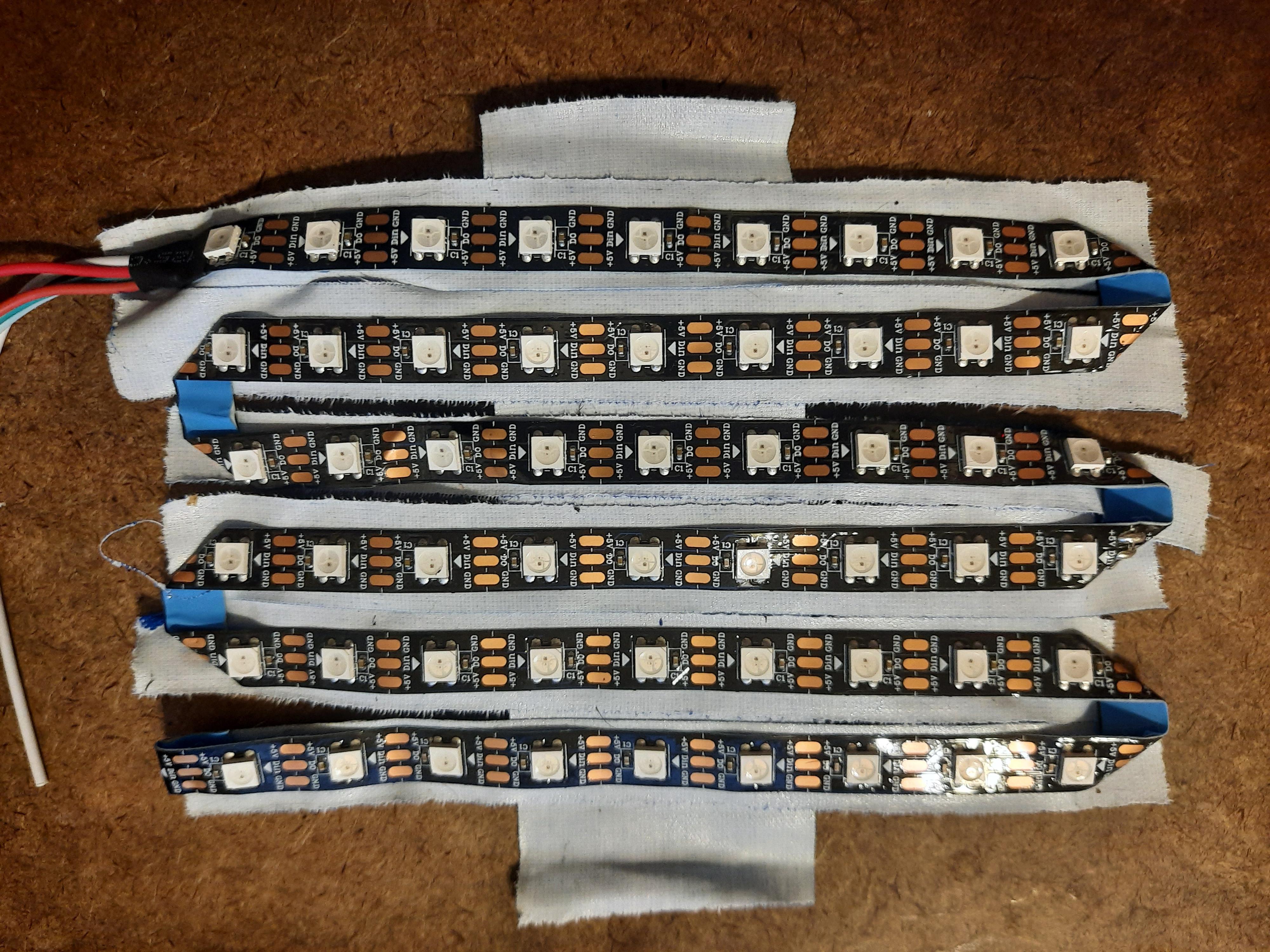
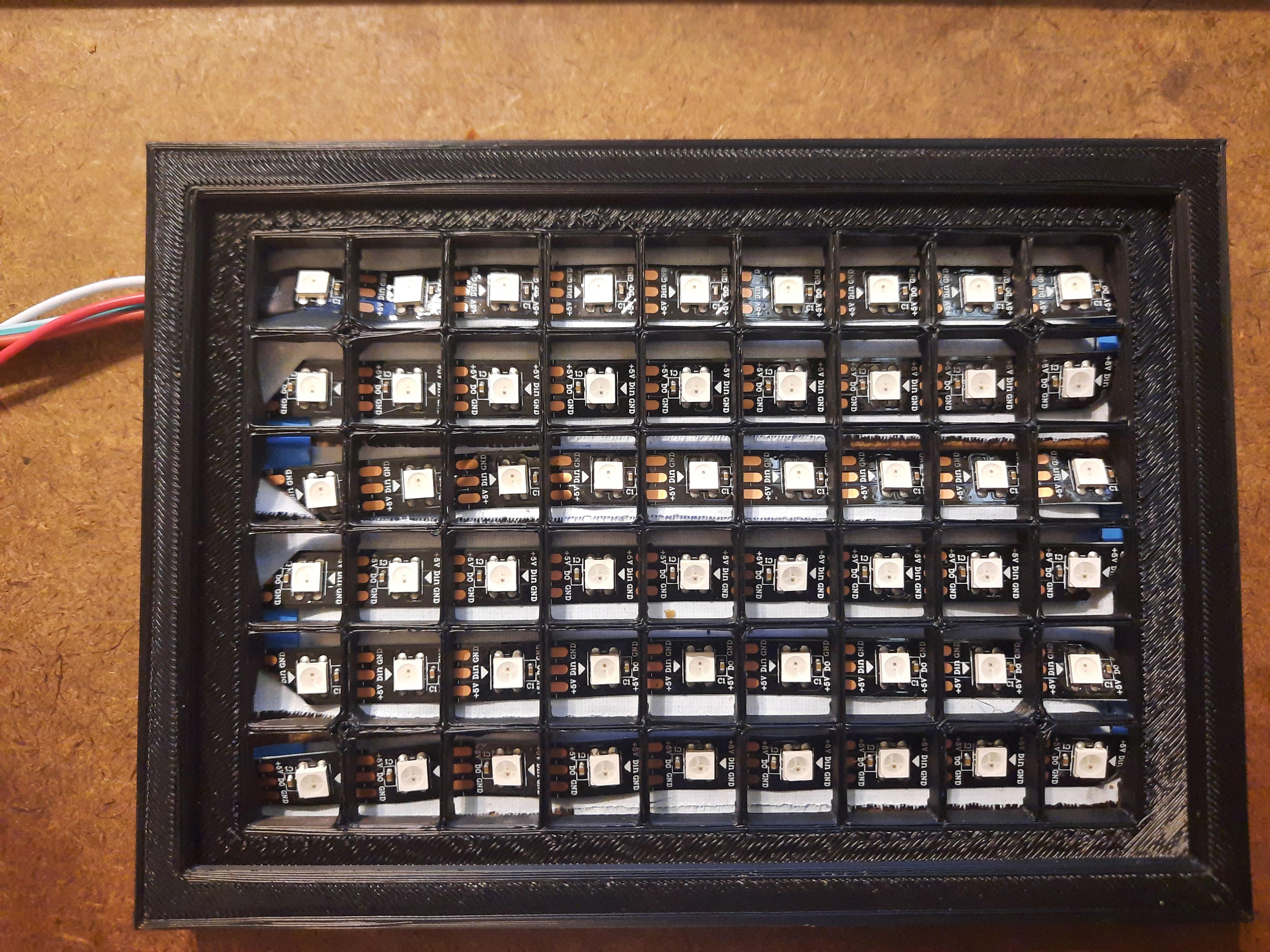
Cut the LED strip so that there are 58 continuous LED elements. Make sure that the input connections on the input end (top left) are included. Lay down strips of tape and place the strip as noted. Follow the guide for laying down on the tape. Be careful doing the folds for the turnarounds. Those LEDs under the folds will not be used. Placement is important because each element will have a number that will be assigned for a specific time to light up. Place the grid on top and make sure each LED is centered in its cell. Turn the grid over and secure with more tape. The better the connection to the back side of the grid, the less light bleed there will be between cells.
Wire the Clock Module, LED Strip, and Buttons to the Arduino
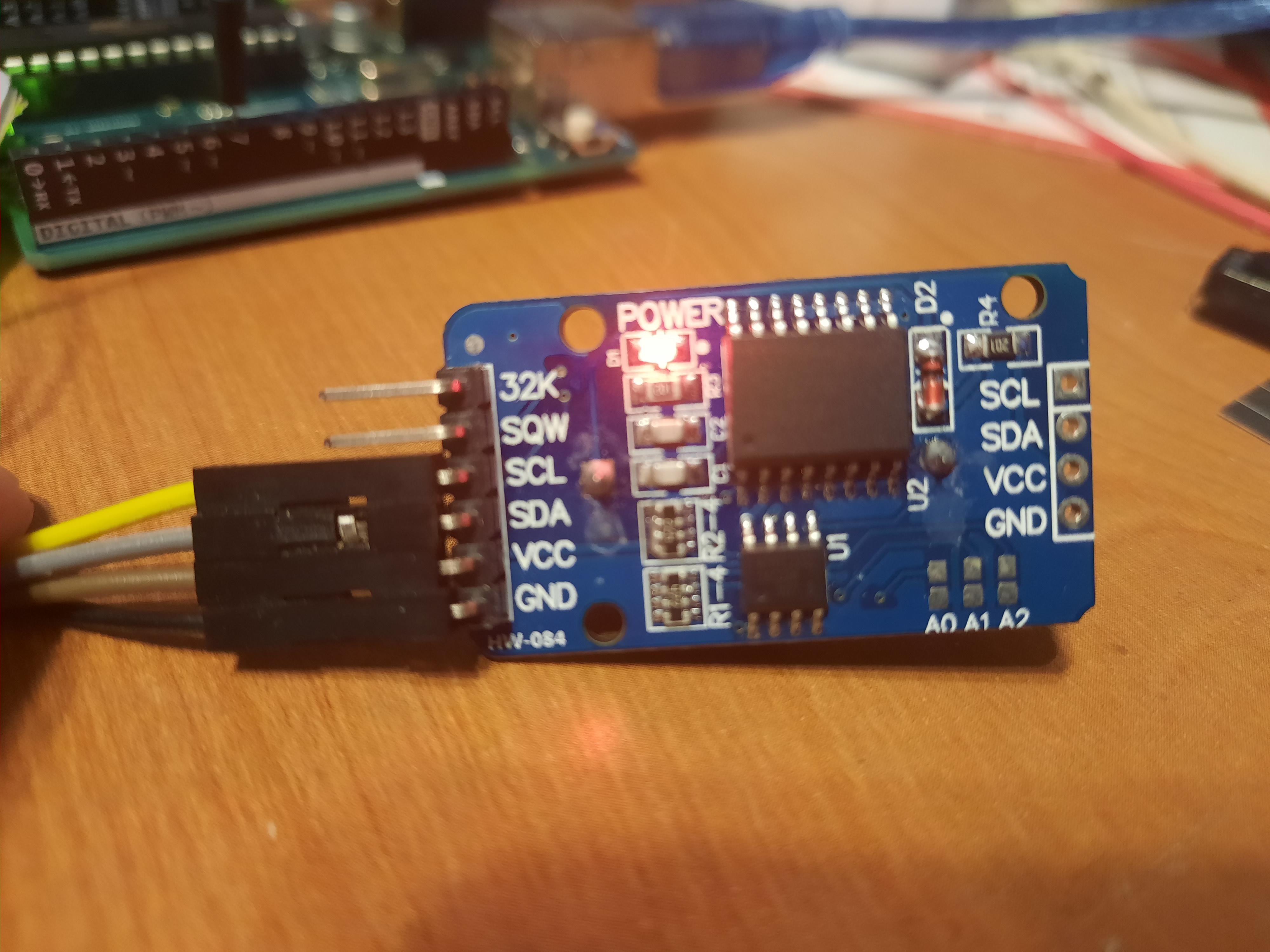

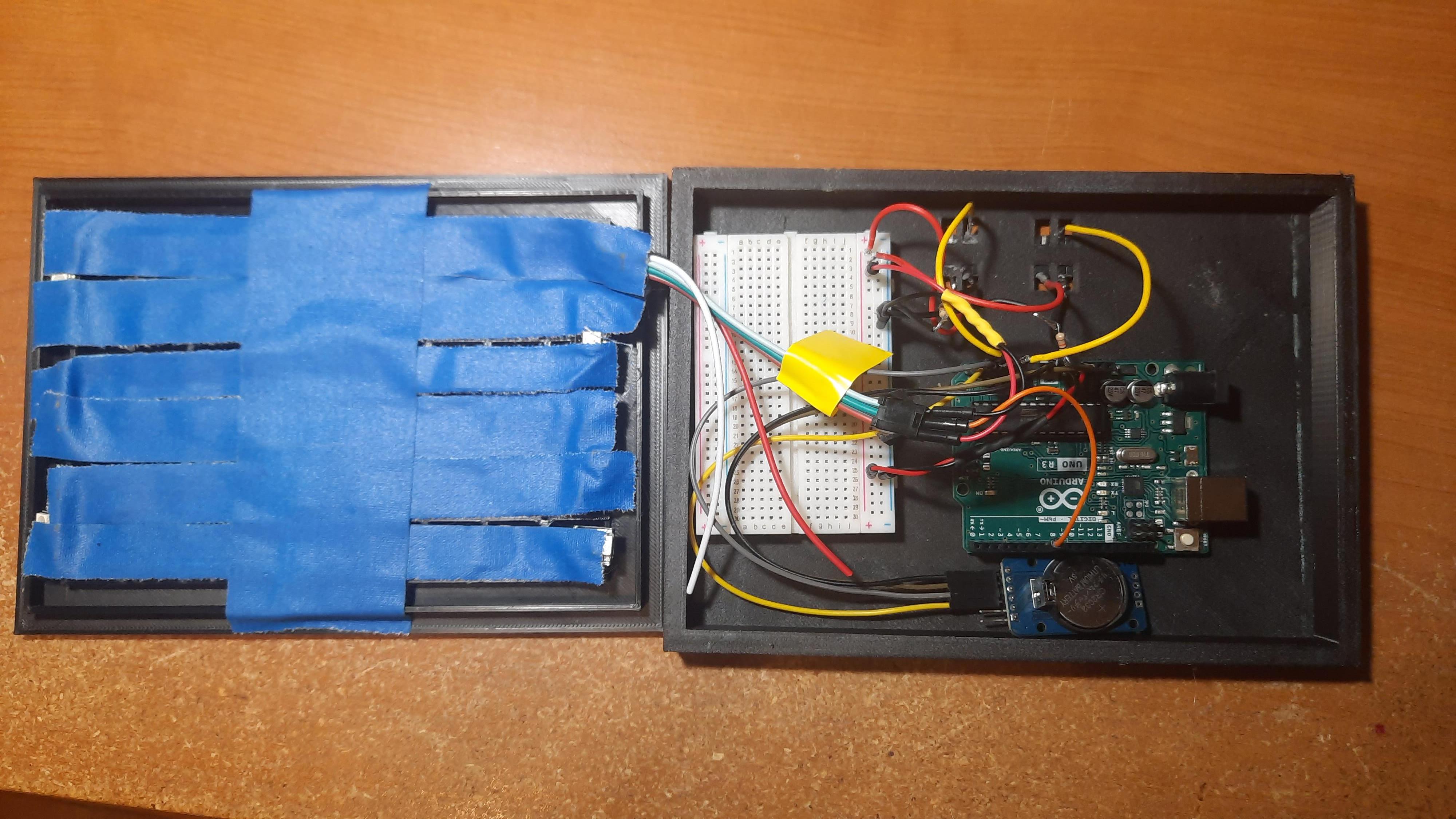
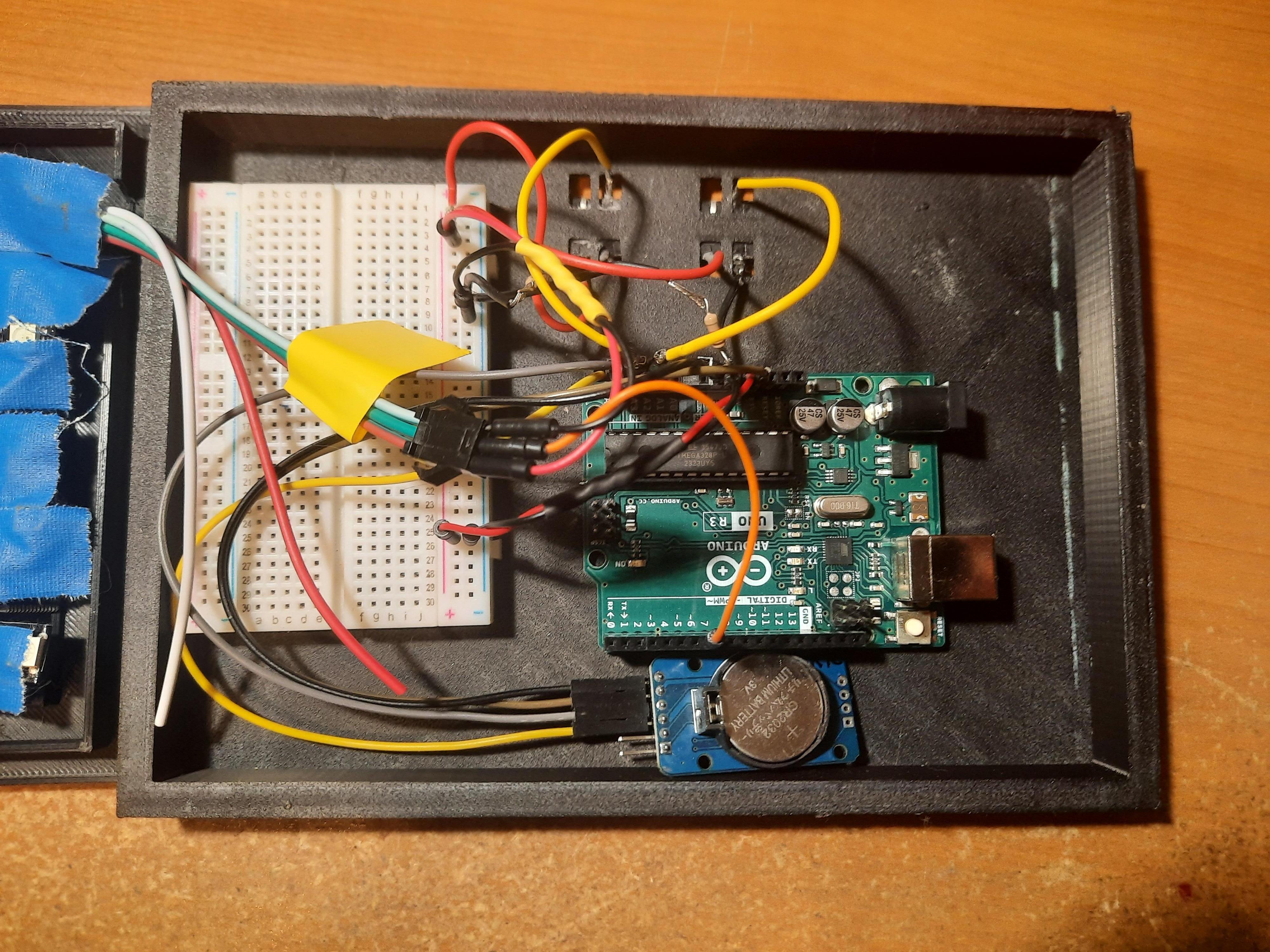
Wire the Arduino, buttons, and clock module as described below. The wiring notes are also in the .ino code.
// DS3231 - RTC Clock module:
// SCL pin -> to A5
// SDA pin -> to A4
// VCC pin -> to 3.3v
// GND pin -> to GND
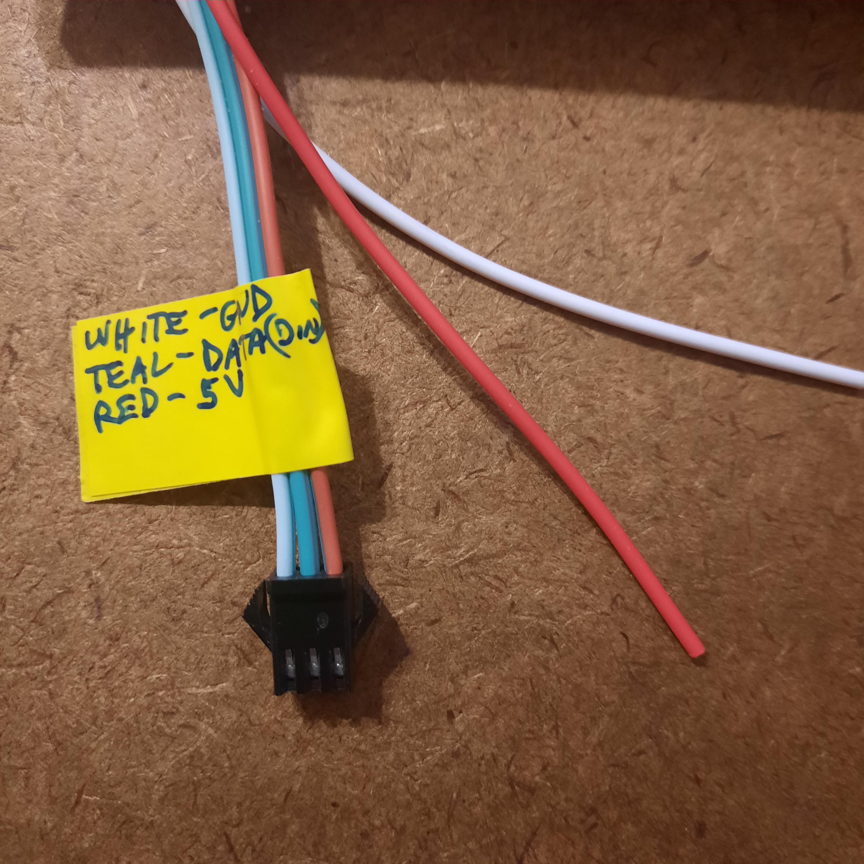
// LED strip:
// LED strip white GND pin -> to GND
// LED strip teal data pin -> to D7
// LED strip red 5v pin -> to 5v
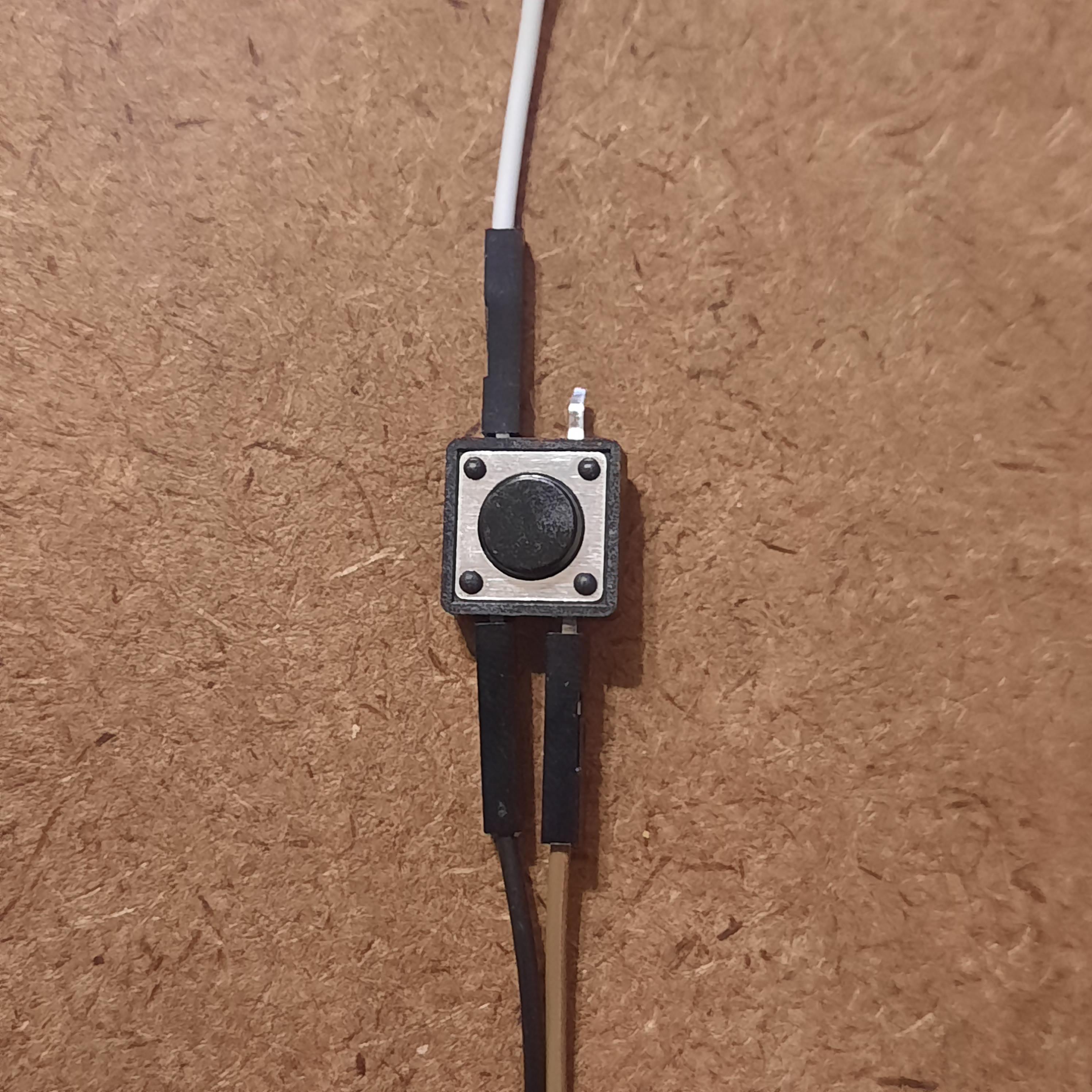
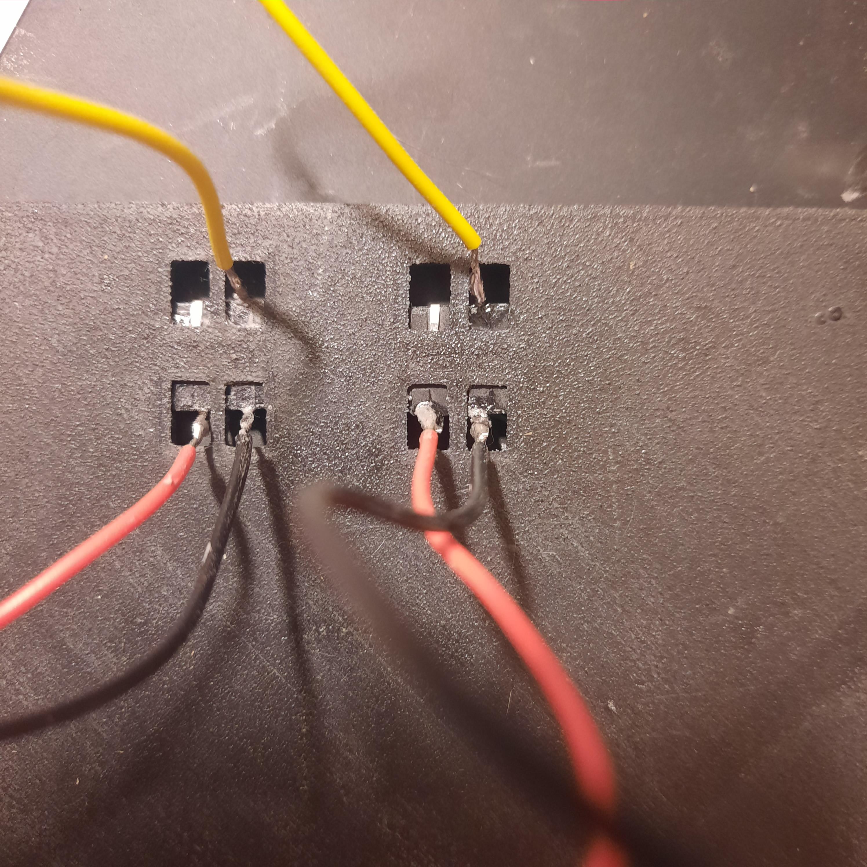
// Pushbuttons: (as you look at the button side)
// pushbutton hh = hours
// Top left -> (data) pin to A2
// Top right -> not used
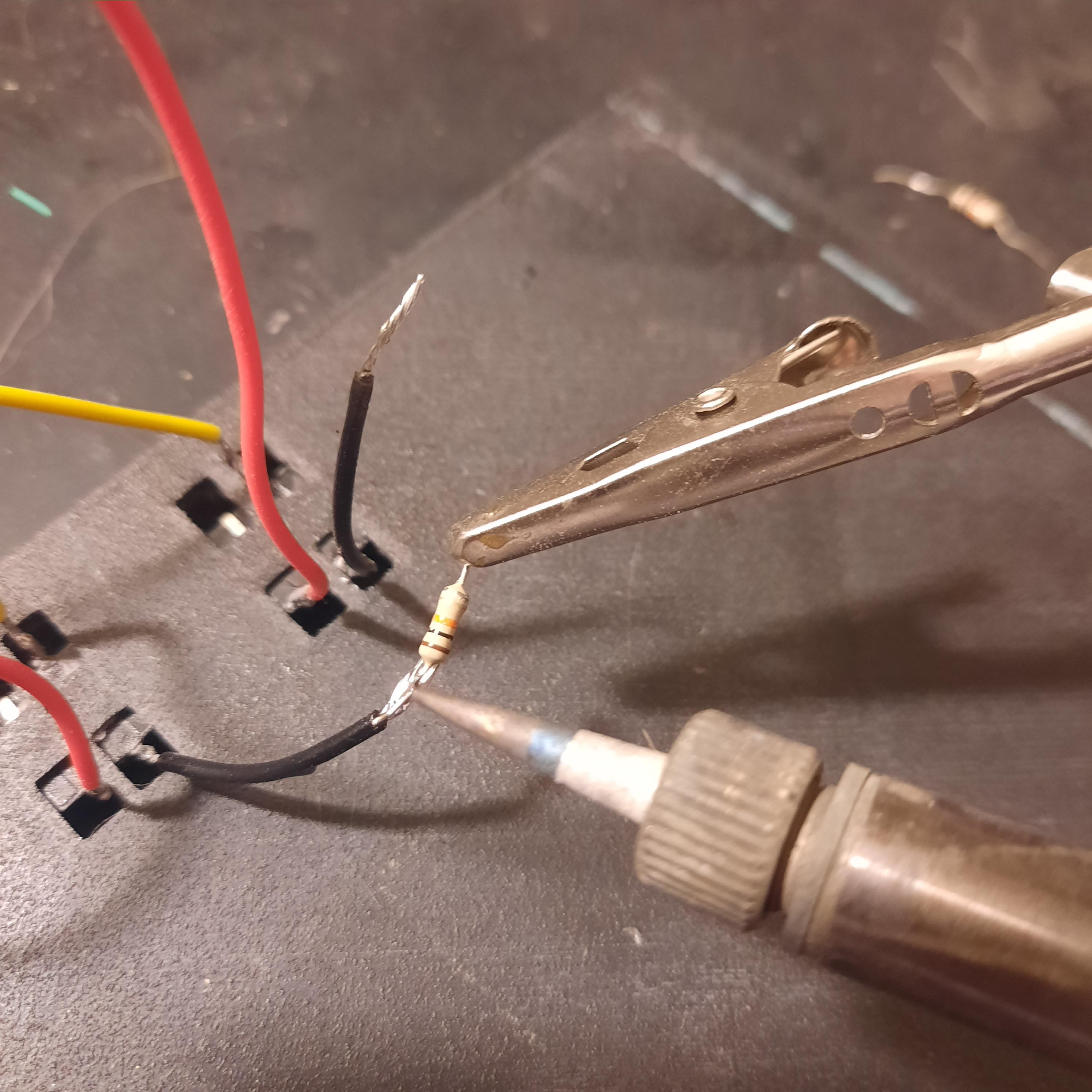
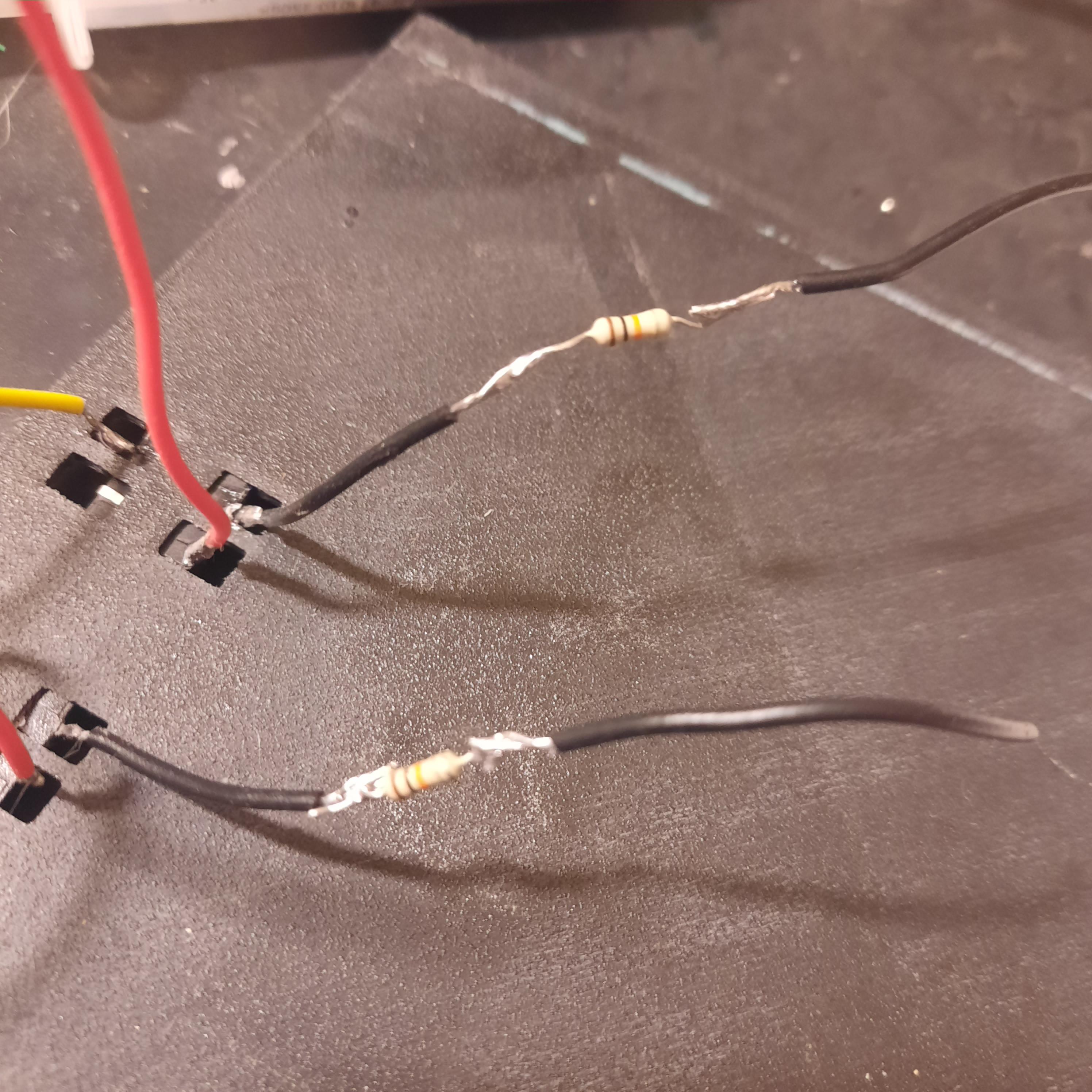
// Lower left -> to 10Kohm resistor, through to GND
// Lower right -> to 5v
//
// pushbutton mm = minutes
// Top left -> (data) pin to A3
// Top right -> not used
// Lower left -> to 10Kohm resistor, through to GND
// Lower right -> to 5v
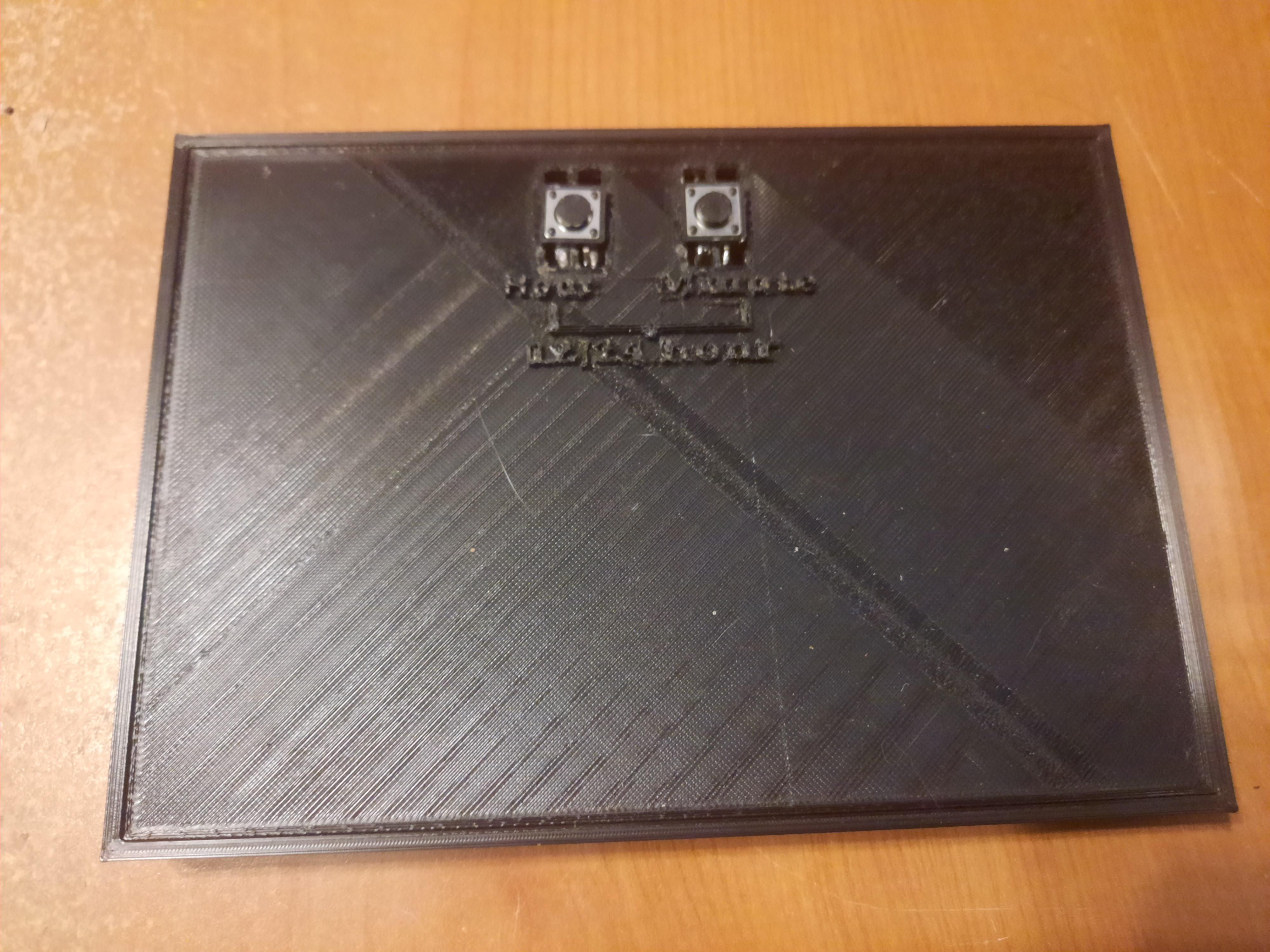
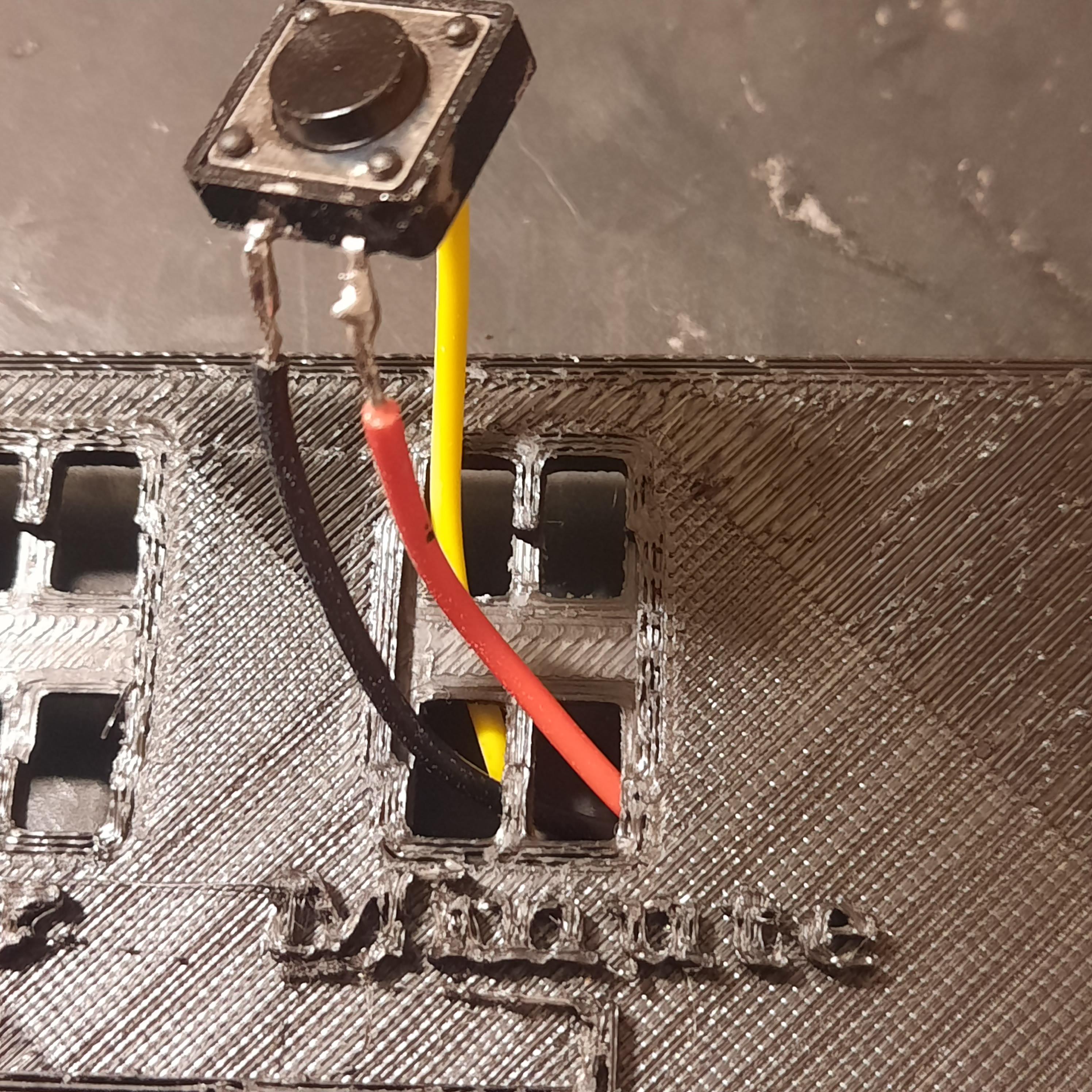
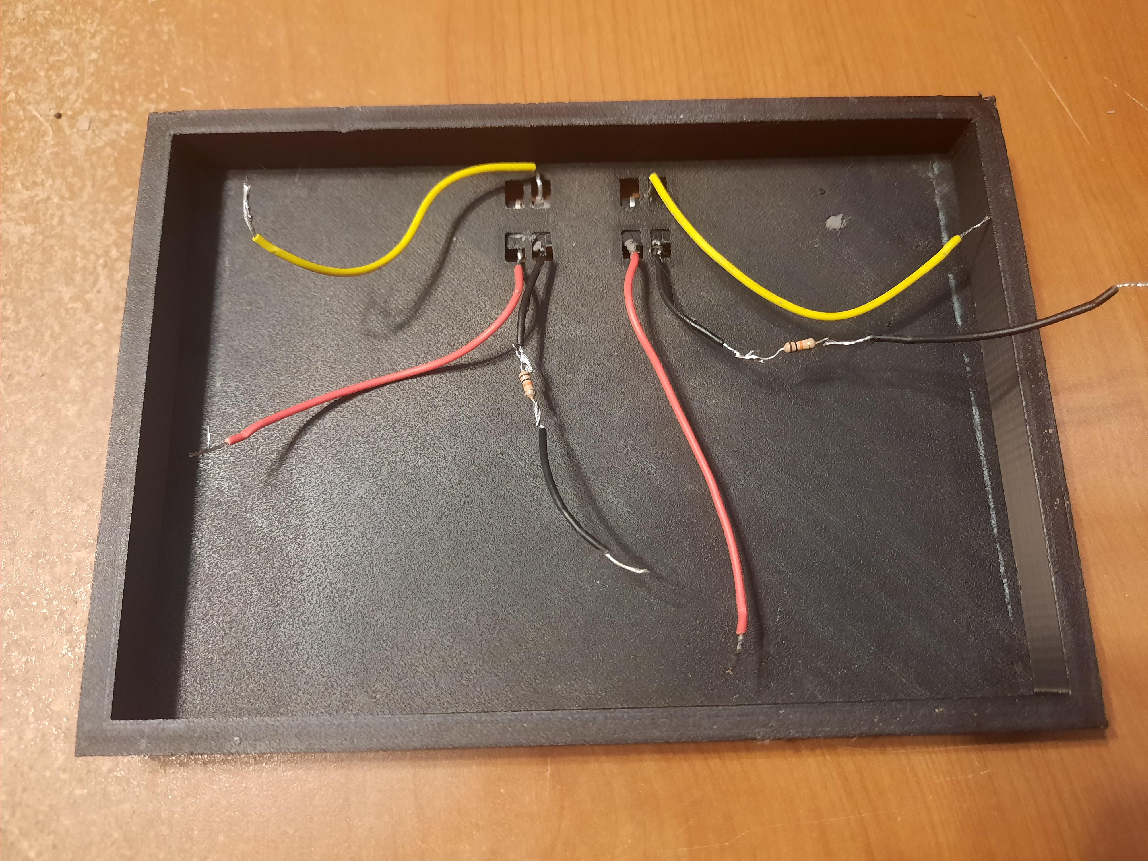
Feed the pushbutton wires though the back of the base, and glue the buttons in place. Use a breadboard or solder to link all the 5v connections together, and all the GND connections together, then connect each line to the 5v and GND of the Arduino. NOTE: the 3.3v wire from the clock module will go directly to its corresponding 3.3v slot on the Arduino. Don't connect it to the 5v line.
Position everything in the base. Place the grid, paper, and faceplate on top.
Edit and Upload the Code (twice)
(Note: I included some of the .h files because there are so many available and these are the ones I found to work. You may have to search for and install additional libraries.)
To initialize the clock, find the step to do that in the PuzzClock.ino file (rtc.setTime). Upload and check the time. Now comment out the time setting line and re-upload. This allows the clock module to keep the correct time as long as it is powered with the battery. (If this is not done, the time will reset to the initial set time when the Arduino is powered off and on.)
The time format is initially set to 12-hour format. This can be changed to 24-hour format in the initial Arduino code or at any time after upload by pressing both buttons as noted below.
The clock can now be separated from the computer and plugged into any USB port. It will keep the current time as long as the battery is in the clock module and the timeset line has been commented out as noted above.
Change Time and Format If Desired
To change the time, press either the Hour or Minute button until the desired time is reached.
The clock starts in a 12-hour format. To set to a 24-hour format, or back to 12-hour format, press both the Hour and Minute buttons on the back for less than one second. Use the Hour button to adjust the hour if needed.
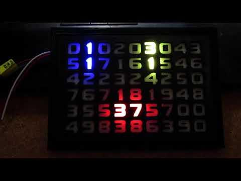
What Time Is It?

Video note: It's difficult to get the lighting and color balance right with a phone cam. But it looks pretty cool in real life!