Pulse Sensor With Arduino(Serial Monitor Control)
by callmeappytechie in Circuits > Arduino
19345 Views, 27 Favorites, 0 Comments
Pulse Sensor With Arduino(Serial Monitor Control)
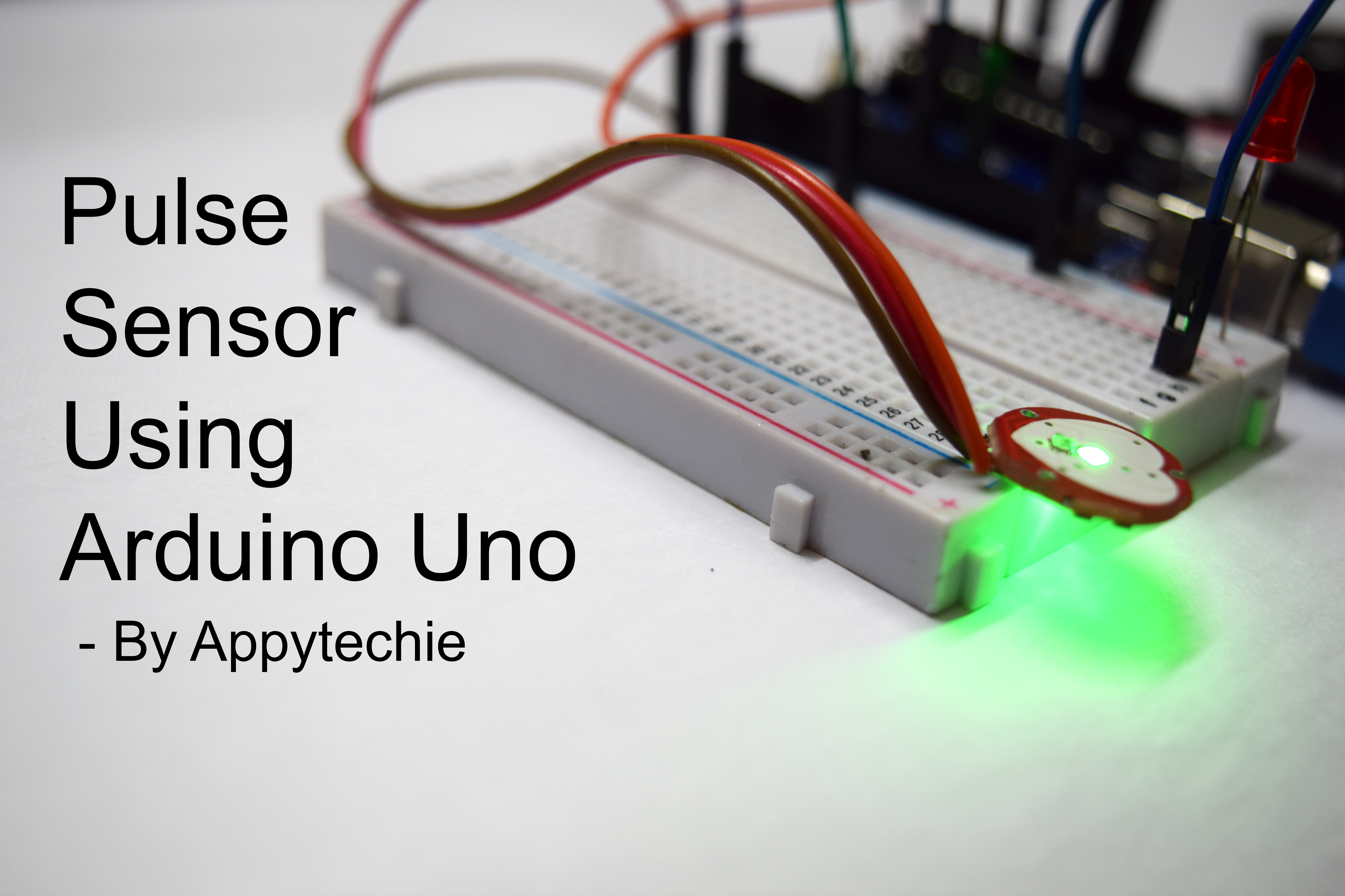
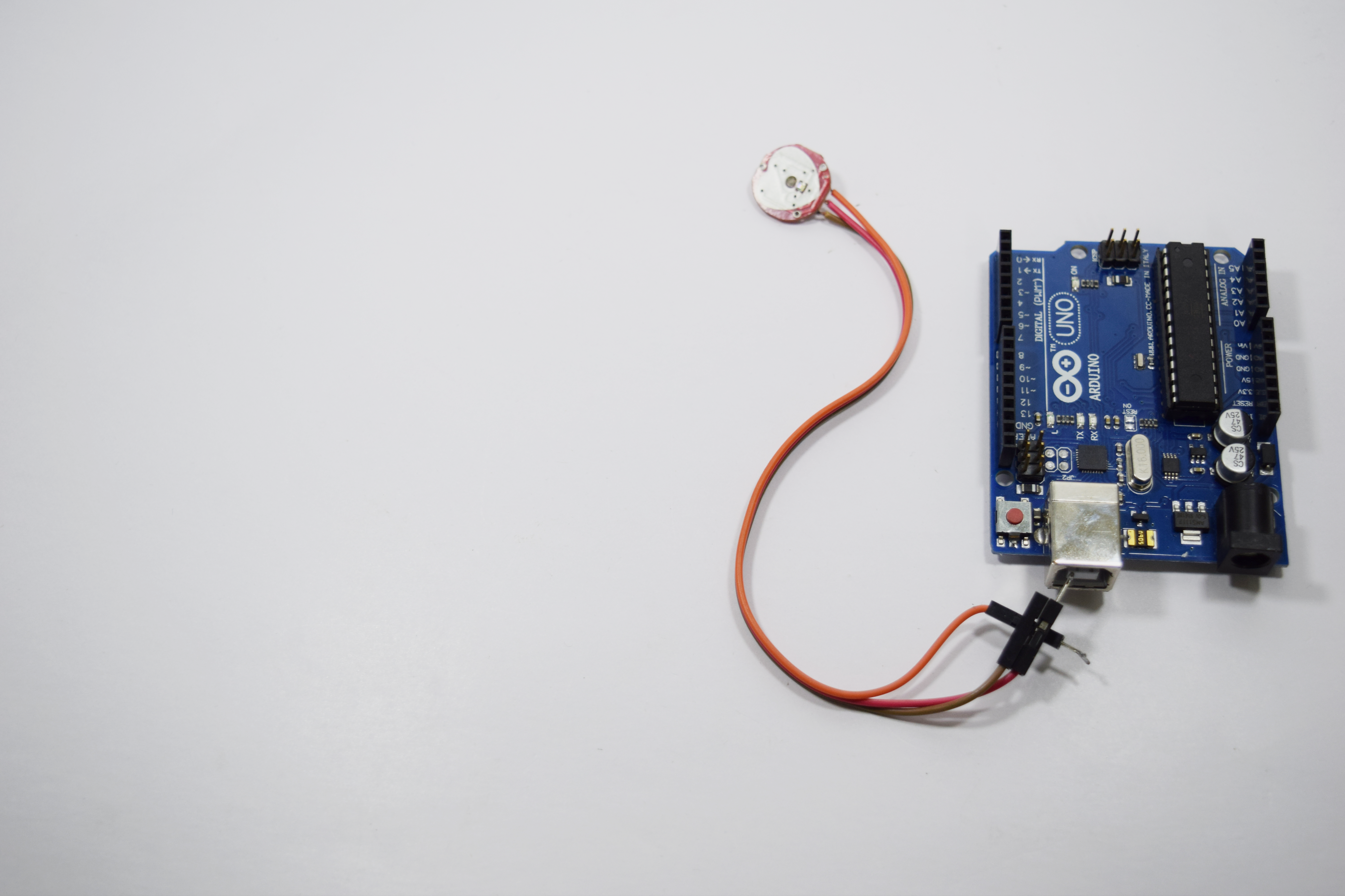
Hi guys!! I'm Sridhar janardhan back with another tutorial.In this tutorial i am going to deal in the catergories of medical electronics.The ible precisely we are going to do is interfacing the pulse sensor to the arduino and read the heart beat of a person through the serial monitor.So before the construction of the Circuit let's gather the components required for the instructable.
If you guys missed out my previous please click here.
Components Required:
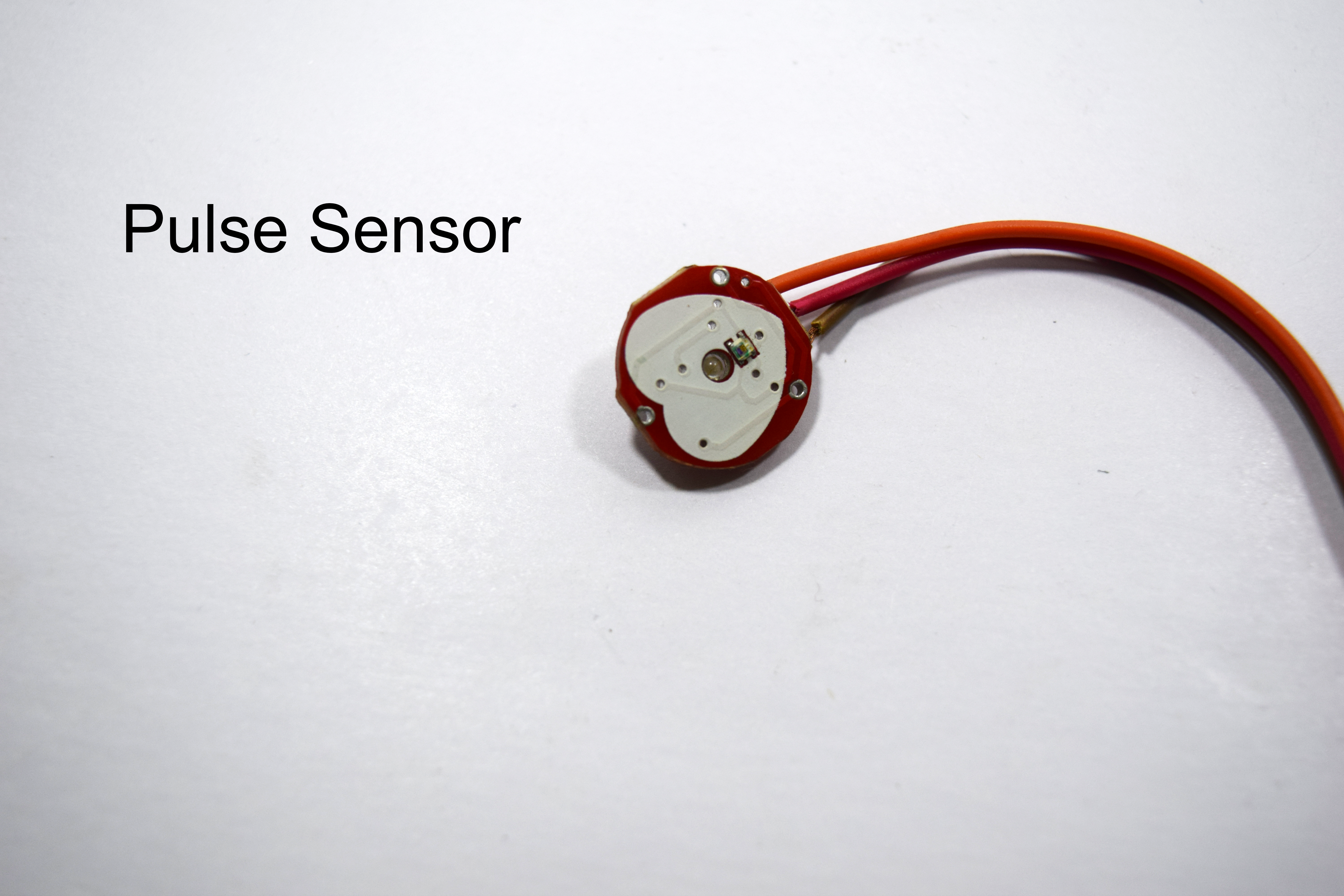
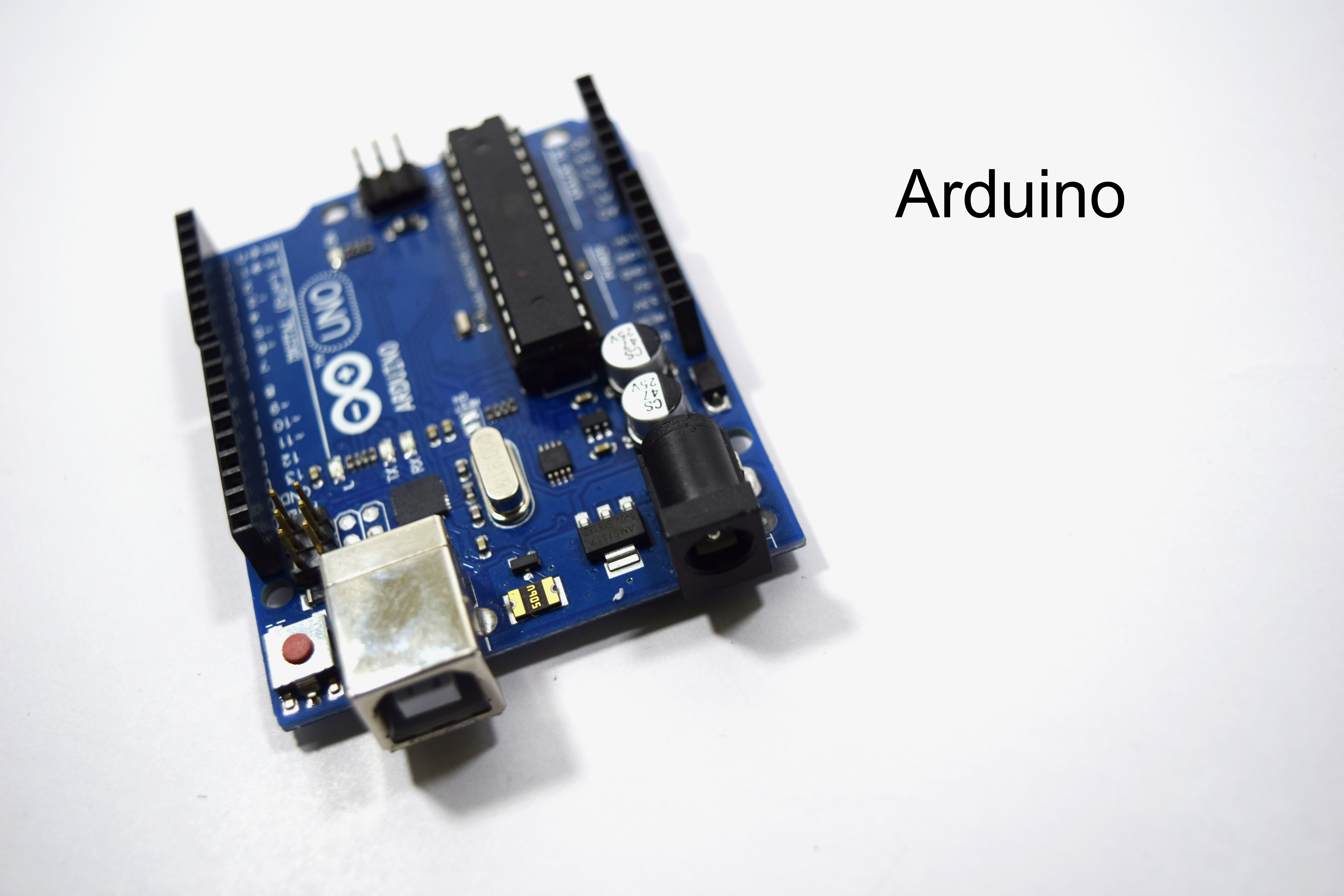
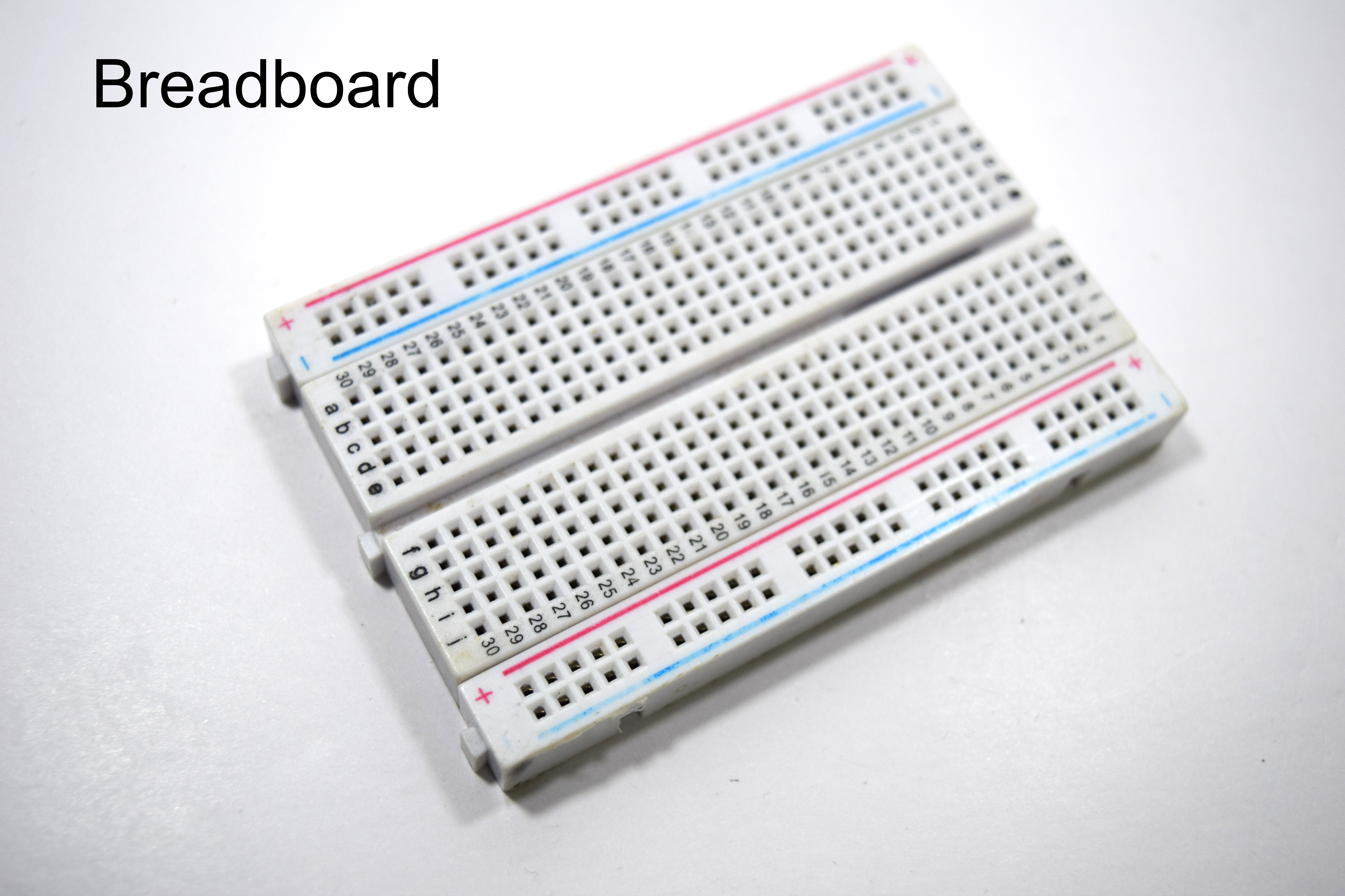
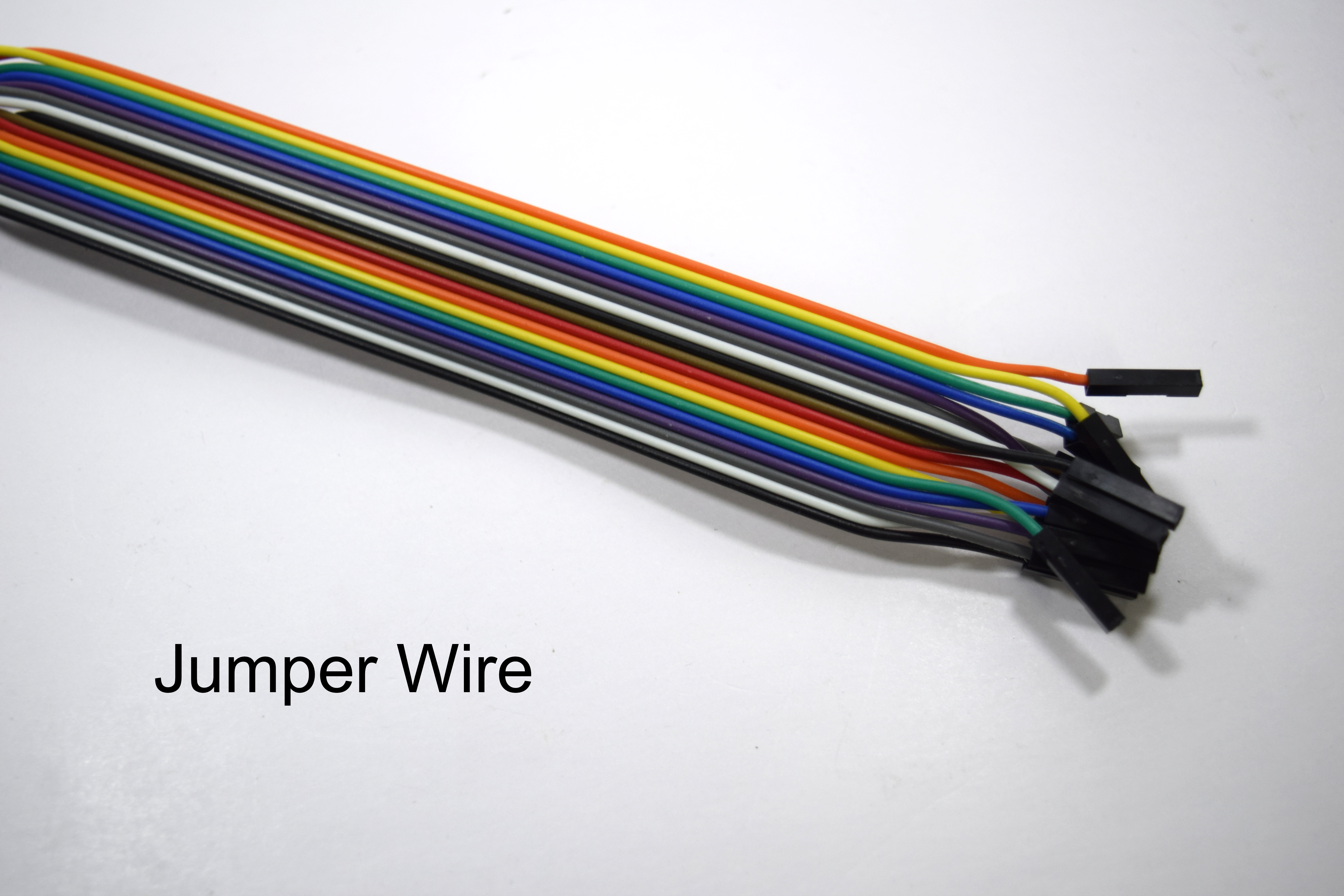
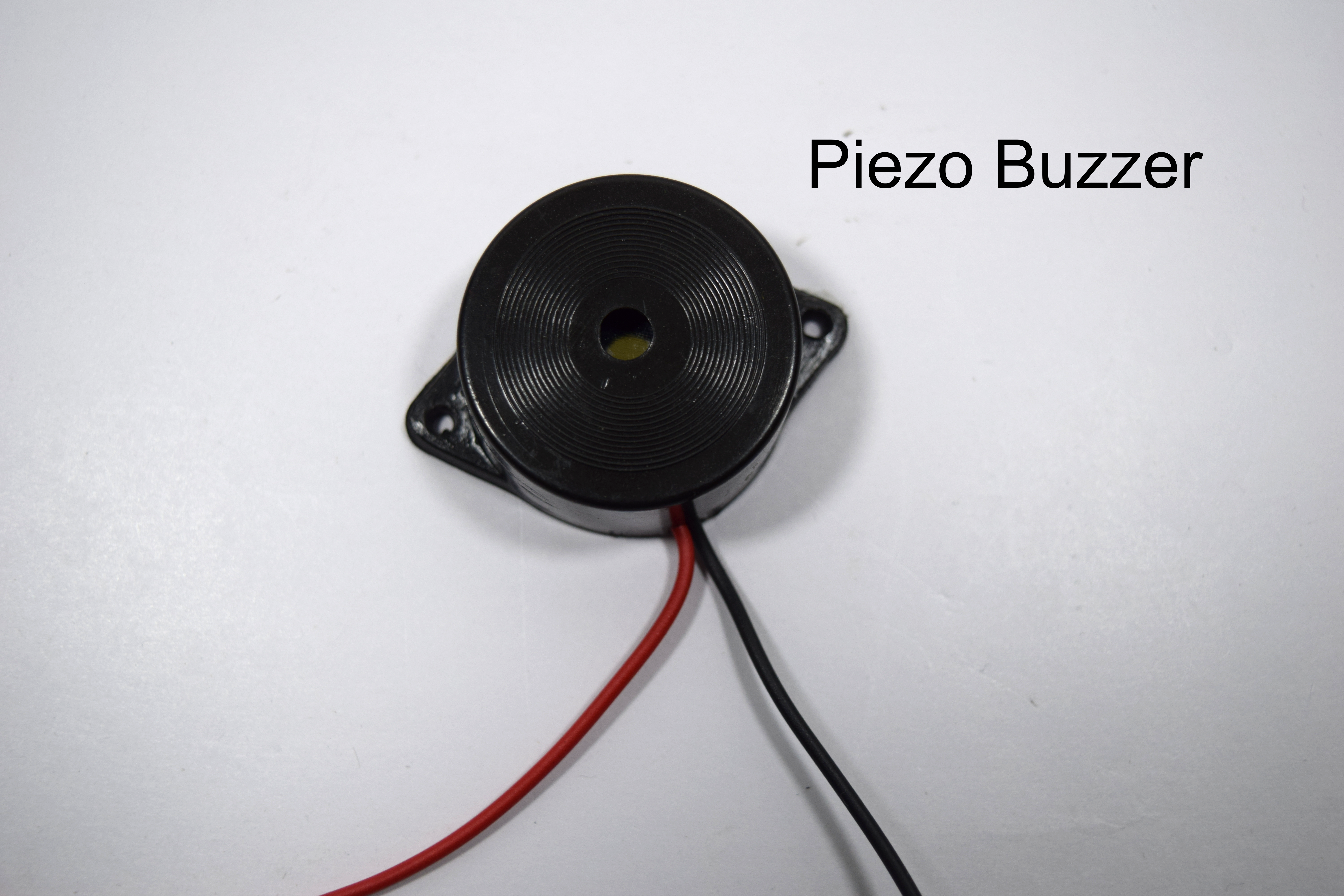
The electronics required are:
- Pulse sensor
- Arduino
- Piezo buzzer
- LED
- Breadboard
- Jumper wire
Assuming after gathering the components let's get into business!!
Interfacing Pulse Sensor:

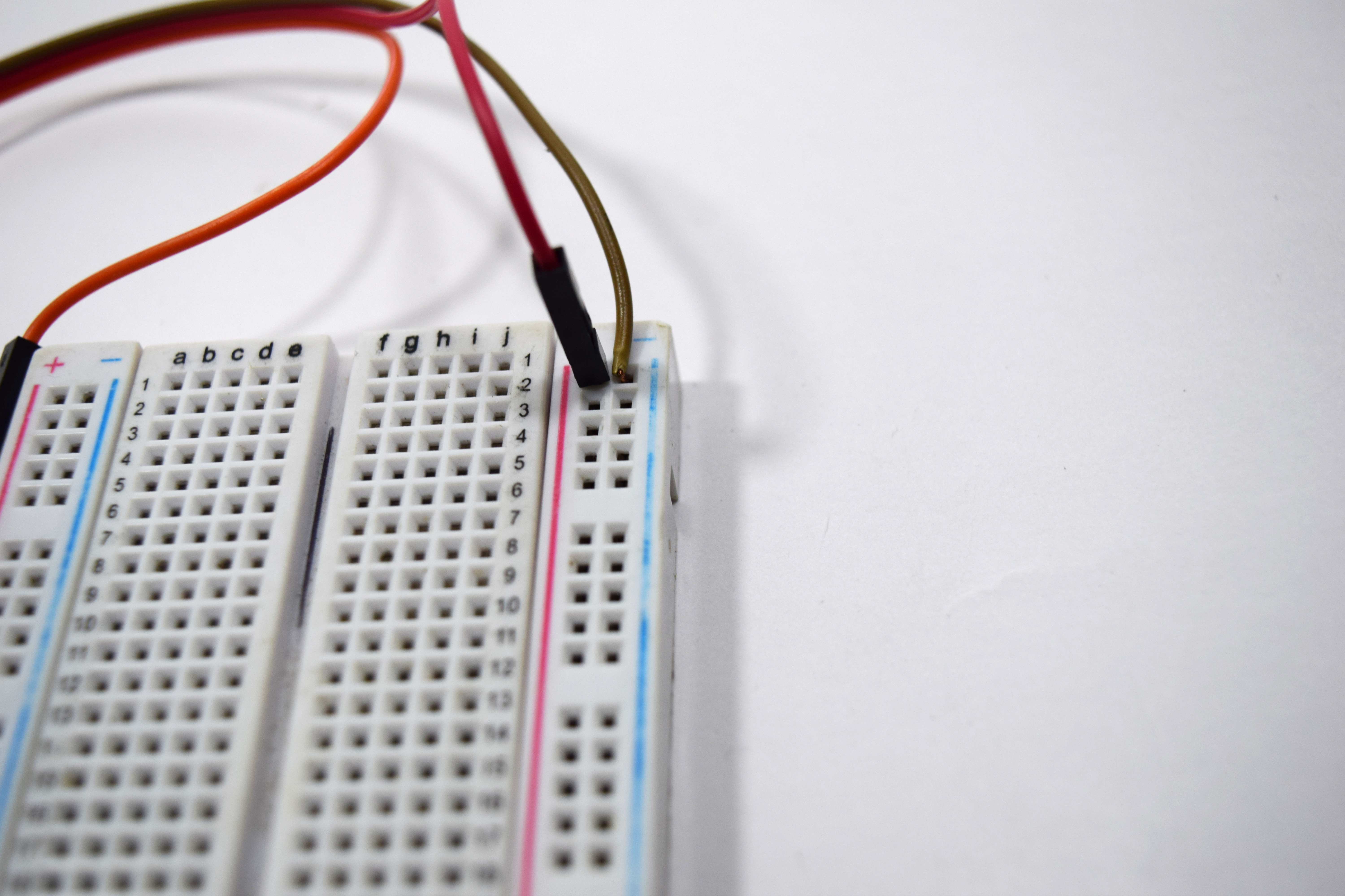
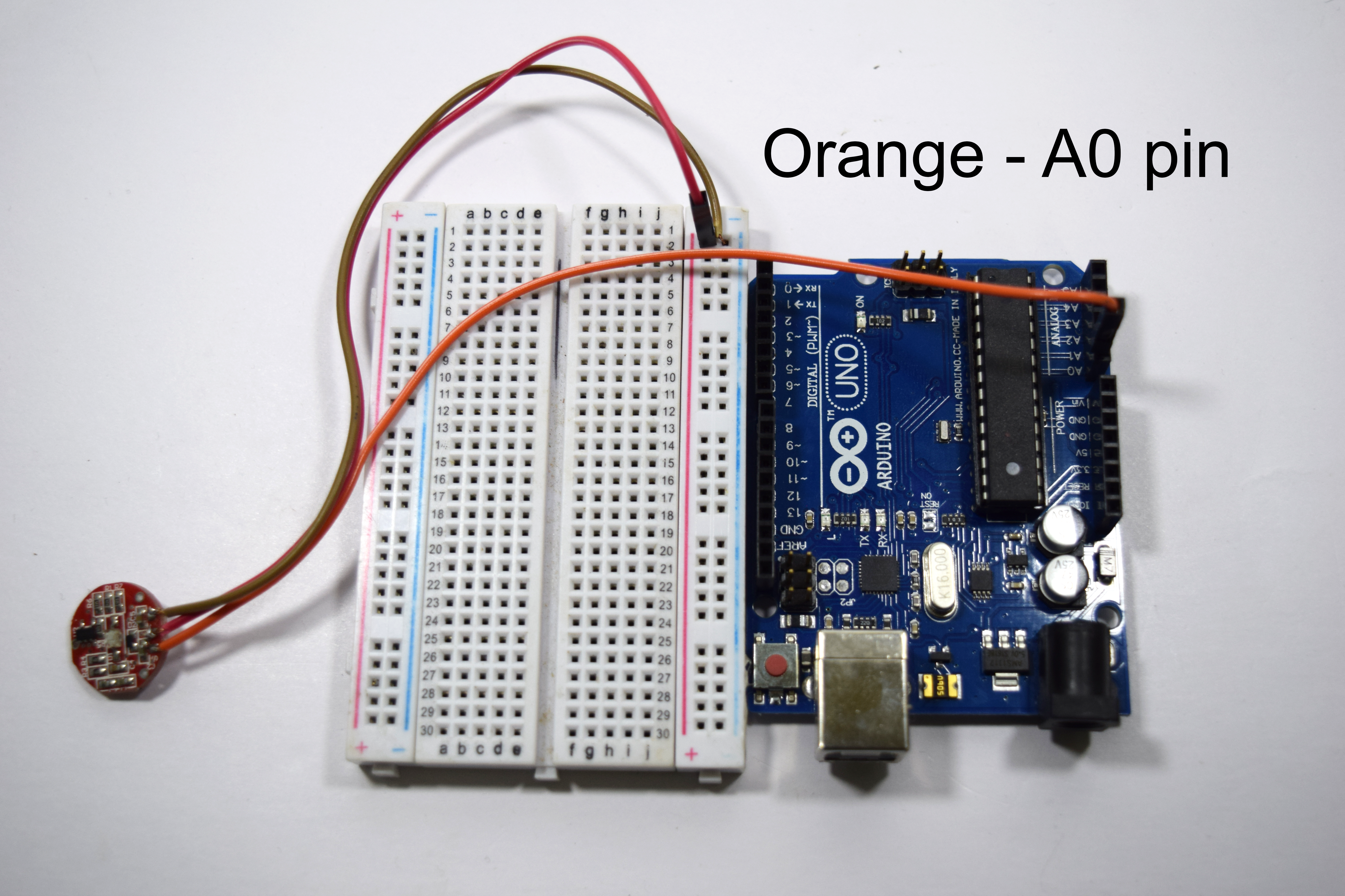
A heart rate monitor is a device that allows one to measure one's heart rate in real time.It can be users who want to easily use this live heart-rate data into their projects.
Pulse sensor consist of three pins:
- VCC pin
- GND pin
- OUT pin or Signal pin
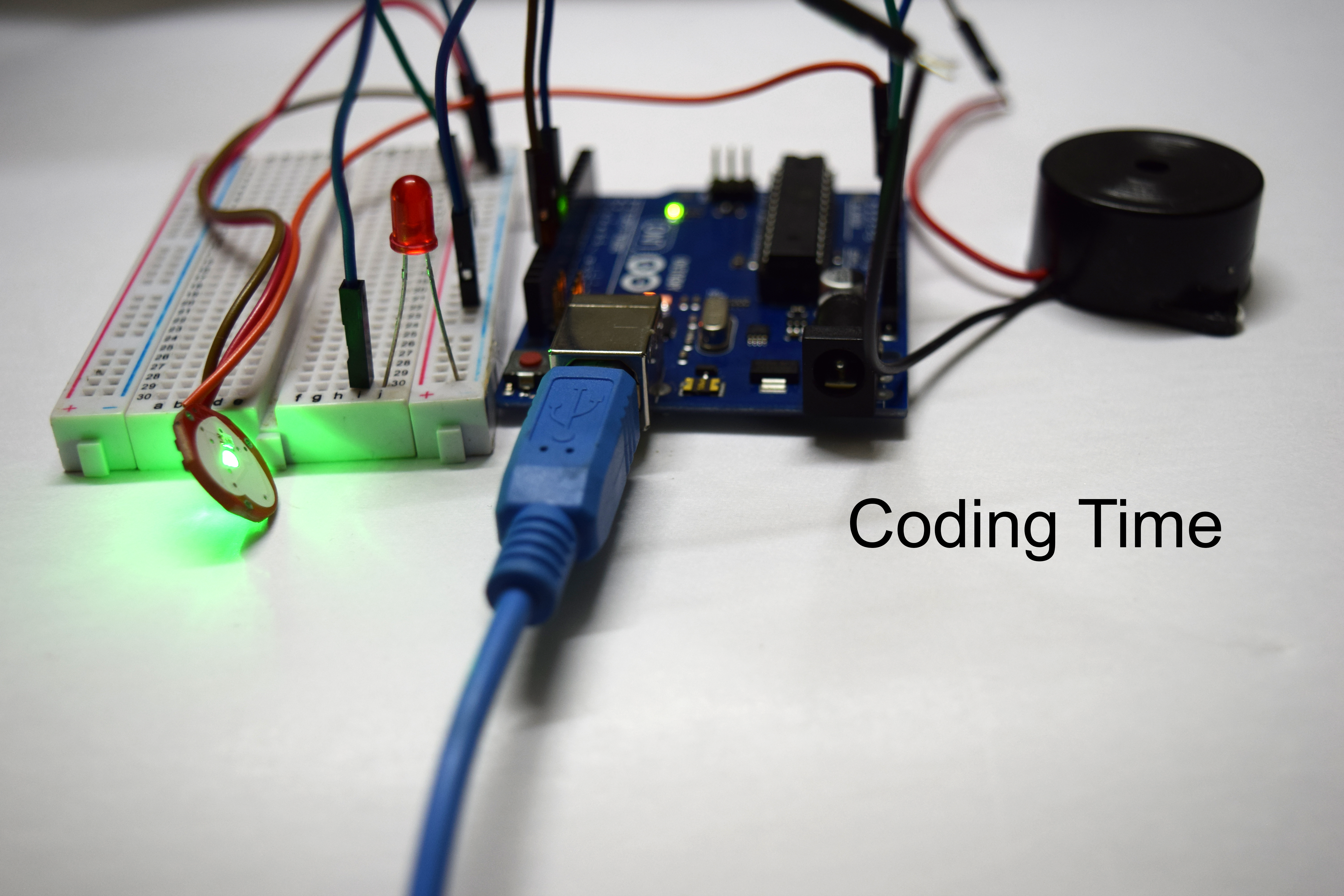
The connection of the Sensor is as follows:
- The VCC pin is connected to the positive railing of the breadboard.
- The GND pin is connected to the negative railing of the breadboard.
- The OUT pin or Signal is connected Analog pin A0 of the Arduino.
Let's now connect piezo buzzer and LED.
Connection of Piezo Buzzer:
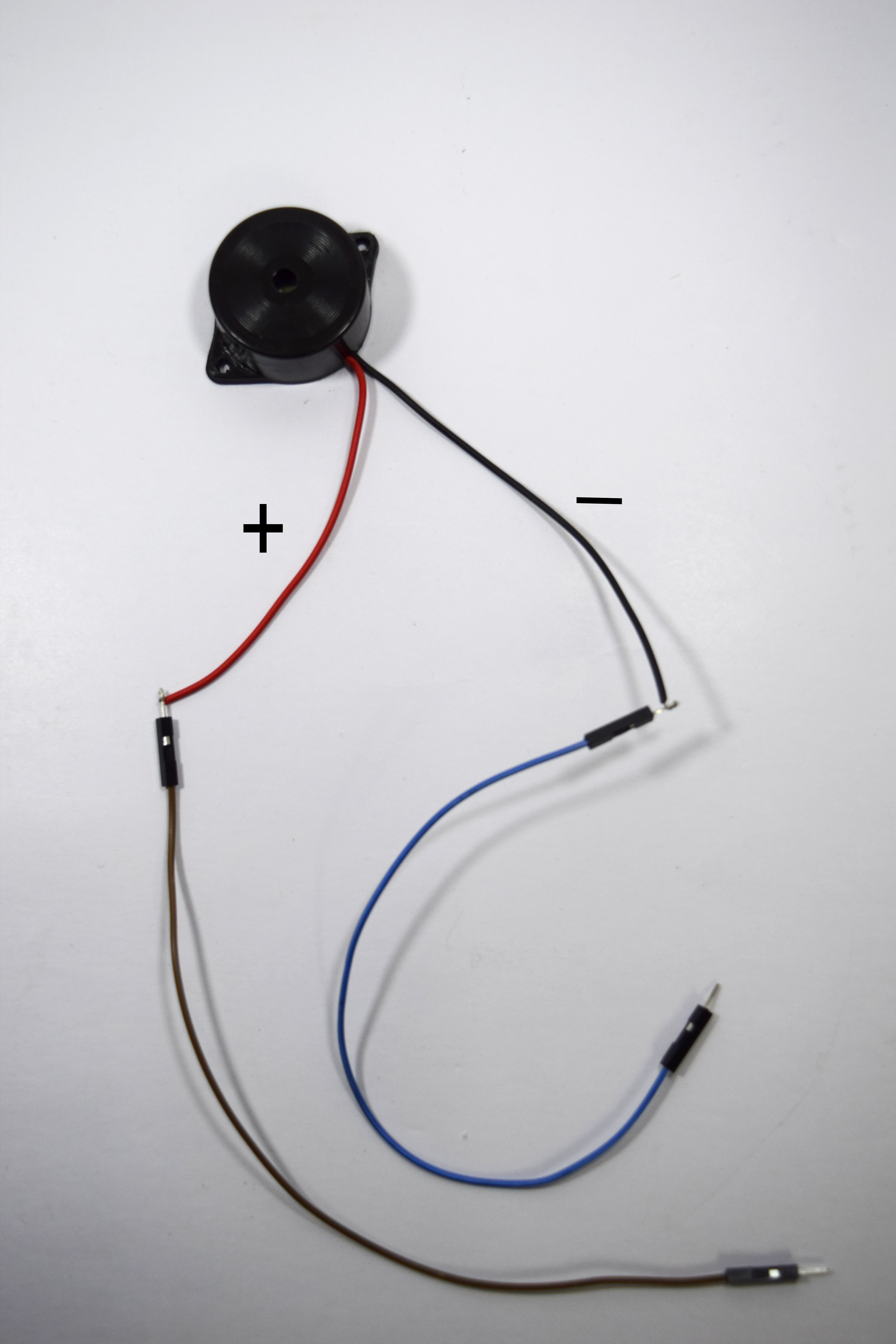
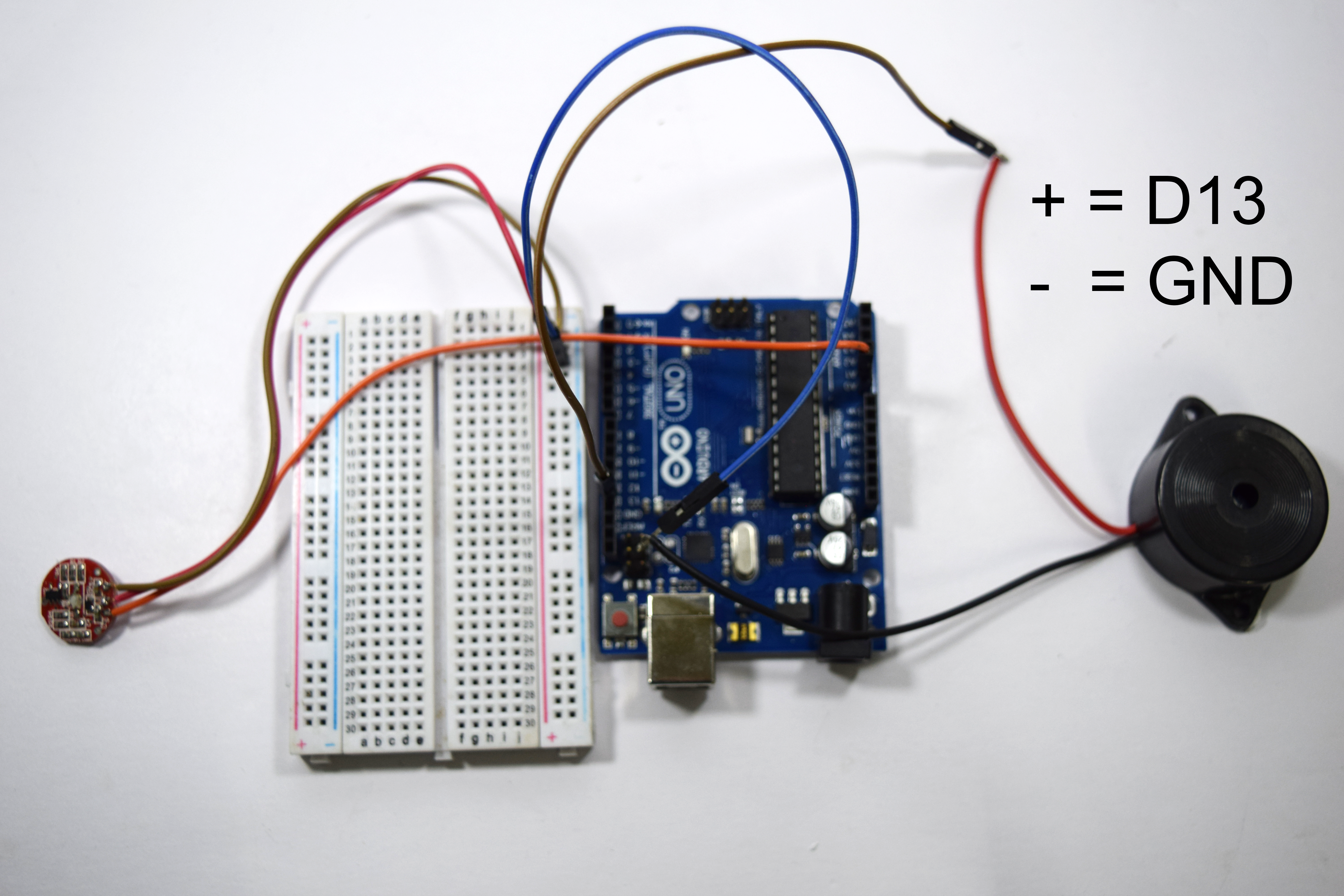
The piezo buzzer has two Wire coming out of the enclosure which is named as anode and cathode.the wire of the Piezo buzzer is extended using the male-male jumper for the sake of interfacing.
The connection of piezo buzzer is as follows:
- The red wire or the anode of the piezo buzzer is connected to the Digital pin 13 of the Arduino.
- The black wire or the cathode of the piezo buzzer is connected to the Negative railing of the breadboard.
The last interfacing left out is LED.
LED Interfacing
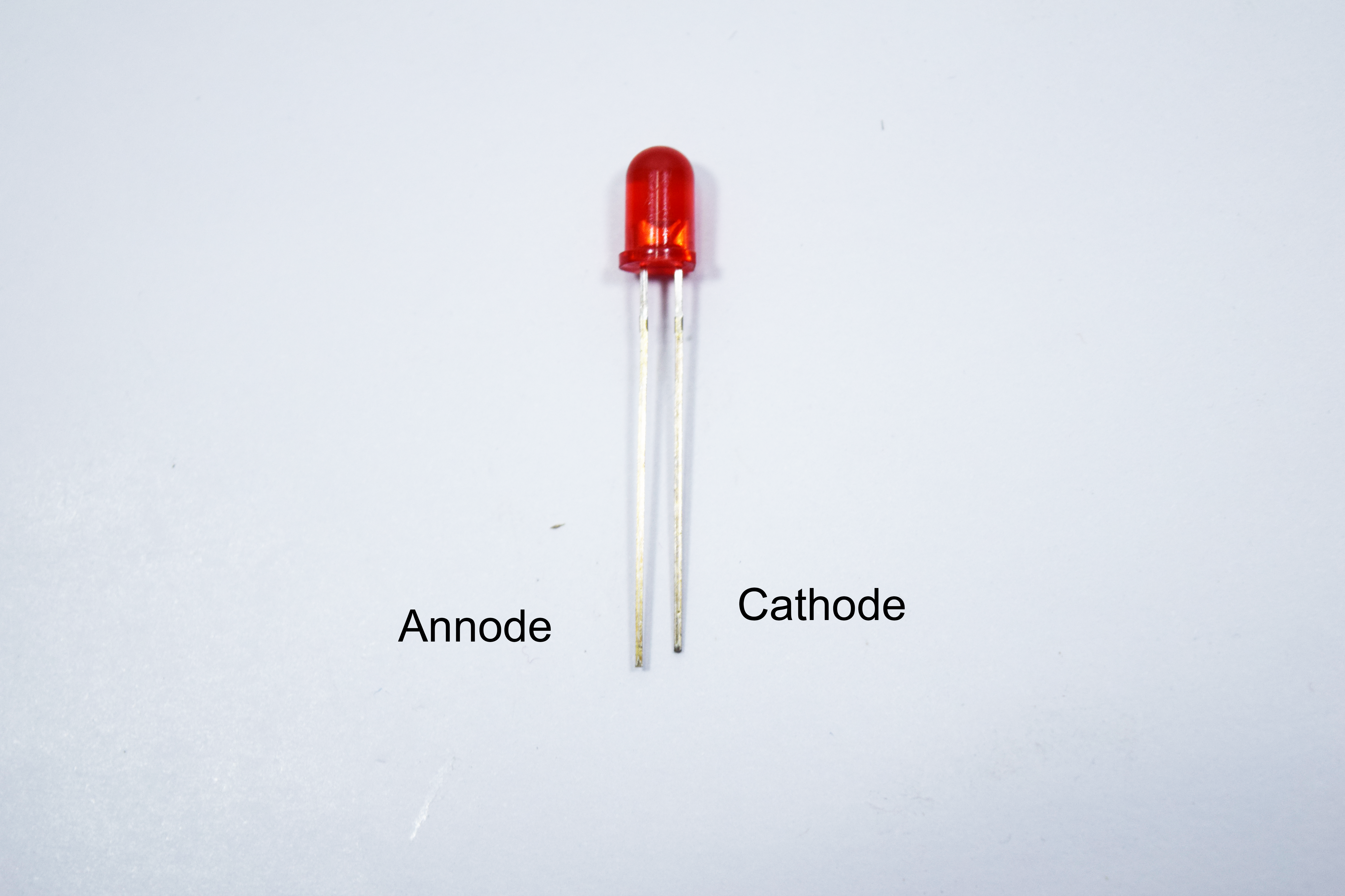

This is also same as piezo buzzer.It is a two terminal device where one terminal is shorter than other.The longer leg is positive or anode terminal and the shorter one is called as negative and cathode terminal.
The connection of LED is as follows:
- The Longer leg or the positive terminal is connected to the digital pin 10
- The shorter leg or the negative terminal is connected to the negative railing of the breadboard.
The hardware interface of the instructable is finished let's get into coding.
The Code
int pulsePin = 0;
int blinkPin = 13;
int fadePin = 8;
int fadeRate = 0;
int BPM;
int Signal;
int IBI = 600;
boolean Pulse = false;
boolean QS = false;
boolean serialVisual = true;
volatile int rate[10];
long sampleCounter = 0;
long lastBeatTime = 0;
int P = 512;
int T = 512;
int thresh = 525;
int amp = 100;
boolean firstBeat = true;
boolean secondBeat = false;
void setup() {
pinMode(blinkPin,OUTPUT); // pin that will blink to your heartbeat!
pinMode(fadePin,OUTPUT); // pin that will fade to your heartbeat!
Serial.begin(115200); // we agree to talk fast!
interruptSetup(); // sets up to read Pulse Sensor signal every 2mS // IF YOU ARE POWERING The Pulse Sensor AT VOLTAGE LESS THAN THE BOARD VOLTAGE, // UN-COMMENT THE NEXT LINE AND APPLY THAT VOLTAGE TO THE A-REF PIN //
analogReference(EXTERNAL); }
// Where the Magic Happens
void loop() {
serialOutput();
if (QS == true) // A Heartbeat Was Found {
// BPM and IBI have been Determined // Quantified Self "QS" true when arduino finds a heartbeat
fadeRate = 255; // Makes the LED Fade Effect Happen, Set 'fadeRate' Variable to 255 to fade LED with pulse serialOutputWhenBeatHappens(); // A Beat Happened, Output that to serial.
QS = false; // reset the Quantified Self flag for next time }
ledFadeToBeat(); // Makes the LED Fade Effect Happen
delay(20); // take a break }
void ledFadeToBeat() {
fadeRate -= 15; // set LED fade value
fadeRate = constrain(fadeRate,0,255); // keep LED fade value from going into negative numbers! analogWrite(fadePin,fadeRate); //
fade LED }
void interruptSetup() { // Initializes Timer2 to throw an interrupt every 2mS.
TCCR2A = 0x02; // DISABLE PWM ON DIGITAL PINS 3 AND 11, AND GO INTO CTC MODE
TCCR2B = 0x06; // DON'T FORCE COMPARE, 256 PRESCALER
OCR2A = 0X7C; // SET THE TOP OF THE COUNT TO 124 FOR 500Hz SAMPLE RATE
TIMSK2 = 0x02; // ENABLE INTERRUPT ON MATCH BETWEEN TIMER2 AND OCR2A
sei(); // MAKE SURE GLOBAL INTERRUPTS ARE ENABLED }
void serialOutput() { // Decide How To Output Serial.
if (serialVisual == true) {
arduinoSerialMonitorVisual('-', Signal); // goes to function that makes Serial Monitor Visualizer } else { sendDataToSerial('S', Signal); // goes to sendDataToSerial function } }
void serialOutputWhenBeatHappens()
{
if (serialVisual == true) // Code to Make the Serial Monitor Visualizer Work
{ Serial.print("*** Heart-Beat Happened *** "); //ASCII Art Madness
Serial.print("BPM: ");
Serial.println(BPM); }
else {
sendDataToSerial('B',BPM); // send heart rate with a 'B' prefix sendDataToSerial('Q',IBI); // send time between beats with a 'Q' prefix }
}
void arduinoSerialMonitorVisual(char symbol, int data ) {
const int sensorMin = 0; // sensor minimum, discovered through experiment
const int sensorMax = 1024; // sensor maximum, discovered through experiment
int sensorReading = data; // map the sensor range to a range of 12 options:
int range = map(sensorReading, sensorMin, sensorMax, 0, 11); // do something different depending on the // range value: switch (range) { case 0: Serial.println(""); /////ASCII Art Madness break; case 1: Serial.println("---"); break; case 2: Serial.println("------"); break; case 3: Serial.println("---------"); break; case 4: Serial.println("------------"); break; case 5: Serial.println("--------------|-"); break; case 6: Serial.println("--------------|---"); break; case 7: Serial.println("--------------|-------"); break; case 8: Serial.println("--------------|----------"); break; case 9: Serial.println("--------------|----------------"); break; case 10: Serial.println("--------------|-------------------"); break; case 11: Serial.println("--------------|-----------------------"); break; } }
void sendDataToSerial(char symbol, int data ) {
Serial.print(symbol); Serial.println(data); }
ISR(TIMER2_COMPA_vect) //triggered when Timer2 counts to 124 { cli(); // disable interrupts while we do this Signal = analogRead(pulsePin); // read the Pulse Sensor sampleCounter += 2; // keep track of the time in mS with this variable int N = sampleCounter - lastBeatTime; // monitor the time since the last beat to avoid noise // find the peak and trough of the pulse wave if(Signal < thresh && N > (IBI/5)*3) // avoid dichrotic noise by waiting 3/5 of last IBI { if (Signal < T) // T is the trough { T = Signal; // keep track of lowest point in pulse wave } }
if(Signal > thresh && Signal > P) { // thresh condition helps avoid noise P = Signal; // P is the peak } // keep track of highest point in pulse wave
// NOW IT'S TIME TO LOOK FOR THE HEART BEAT // signal surges up in value every time there is a pulse if (N > 250) { // avoid high frequency noise if ( (Signal > thresh) && (Pulse == false) && (N > (IBI/5)*3) ) { Pulse = true; // set the Pulse flag when we think there is a pulse digitalWrite(blinkPin,HIGH); // turn on pin 13 LED IBI = sampleCounter - lastBeatTime; // measure time between beats in mS lastBeatTime = sampleCounter; // keep track of time for next pulse if(secondBeat) { // if this is the second beat, if secondBeat == TRUE secondBeat = false; // clear secondBeat flag for(int i=0; i<=9; i++) // seed the running total to get a realisitic BPM at startup { rate[i] = IBI; } } if(firstBeat) // if it's the first time we found a beat, if firstBeat == TRUE { firstBeat = false; // clear firstBeat flag secondBeat = true; // set the second beat flag sei(); // enable interrupts again return; // IBI value is unreliable so discard it } // keep a running total of the last 10 IBI values word runningTotal = 0; // clear the runningTotal variable
for(int i=0; i<=8; i++) { // shift data in the rate array rate[i] = rate[i+1]; // and drop the oldest IBI value runningTotal += rate[i]; // add up the 9 oldest IBI values }
rate[9] = IBI; // add the latest IBI to the rate array runningTotal += rate[9]; // add the latest IBI to runningTotal runningTotal /= 10; // average the last 10 IBI values BPM = 60000/runningTotal; // how many beats can fit into a minute? that's BPM! QS = true; // set Quantified Self flag // QS FLAG IS NOT CLEARED INSIDE THIS ISR } }
if (Signal < thresh && Pulse == true) { // when the values are going down, the beat is over digitalWrite(blinkPin,LOW); // turn off pin 13 LED Pulse = false; // reset the Pulse flag so we can do it again amp = P - T; // get amplitude of the pulse wave thresh = amp/2 + T; // set thresh at 50% of the amplitude P = thresh; // reset these for next time T = thresh; }
if (N > 2500) { // if 2.5 seconds go by without a beat thresh = 512; // set thresh default P = 512; // set P default T = 512; // set T default lastBeatTime = sampleCounter; // bring the lastBeatTime up to date firstBeat = true; // set these to avoid noise secondBeat = false; // when we get the heartbeat back }
sei(); // enable interrupts when youre done! }// end isr
Execution
Assistance:
If any peeps need any assistance in any kind of electronics project leave a comment below or send your project abstract to official.appytechie@gmail.com.
Thank you.