Project_A: Robotic Arm

Nowadays, for us robotics enthusiasts, there is a wide variety of hobby projects available online: wheeled robots, legged robots, robotic arms, etc. A rich variety, indeed, but if there is something most of those hobby projects have all in common is that they are small… and not easily scalable, either! As soon as you put in any weight or demand any force, the joints break and the motors stall; they are not meant for any kind of heavy duty.
So, what if I want to build a robotic arm that is capable of lifting something heavier than a few ounces? What about a few pounds? Yes, but also, you do not want to buy an industrial robotics arm that will set you back some serious bucks, require you to buy and/or learn proprietary software, and then collect dust after you are done playing with it. Is there a middle-of-the-road option?
The purpose of these instructions is to show you how to build a robotics arm that can lift up to 10 pounds, that is not made of plastic, but of iron and wood, that is not insanely expensive, that you can control directly or via a programmable Arduino, and that you can later easily modify to better suit your goals - or even break down into parts for other projects once you are done with it.
While you could totally do this project flying solo, it would be a good idea to team up with a friend or friends and divide the tasks to do. Compared to other projects, this one is much longer.
Disclaimer
DO NOT attempt any of the instructions provided here if you are not comfortable or are unaware of the associated risks of working with hand tools, power tools, machine tools, steel alloys, wood studs, fasteners, electronic components, electronic PCB soldering, electric components, and electricity in general.
The machine depicted in this procedure is only for hobby & research purposes. It is not intended for any commercial or industrial use, or any other use in which a machine failure or malfunction could result in physical or psychological harm to the user(s).
The author assumes no responsibility or liability for any errors or omissions in the content of these instructions. The information contained in these instructions is provided on an "as is" basis with no guarantees of completeness, accuracy, usefulness, or timeliness.
Supplies
Tools Required
· Drill Press or mini-mill machine.
· Metal drill bits set, SAE & Metric (review drawings for all sizes).
· Wood drill bit 5/8”.
· Metal hole cutter 5/8” and 22mm.
· Metal cutting tool (ideal: metal bandsaw / minimum: hacksaw).
· Wood cutting tool (ideal: miter saw / minimum: handsaw).
· Vise and vise pads for round components.
· SAE wrench set / adjustable wrench / screwdrivers.
· Wire cutters / crimpers.
· Measuring tools, such as digital calipers and metal rulers.
· Soldering iron / soldering wire and flux.
· Multimeter that can measure AC/DC Voltage and resistance.
Links for this Project
EBay listing link to buy the PCB Control Board (EA-001):
https://www.ebay.com/itm/395022272020?mkcid=16&mkevt=1&mkrid=711-127632-2357-0&ssspo=lg80m5ante2&sssrc=2047675&ssuid=lg80m5ante2&widget_ver=artemis&media=COPY
Follow this link to access the Share Drive for this project:
https://drive.google.com/drive/folders/1fEwT1D1HdDtRI_HJwpJzbxFVZktn5EZZ?usp=drive_link
Shopping for Parts
“It is the parts that make the machine” – indeed! For this project, you will need a lot of parts. The good news is that all components are available online from various suppliers, except for the PCB Control Board, which I am supplying (see link for listing above); but all other components you can get online, and in the case of fasteners, wood and metal, you can even get from your local hardware store.
And for the rest of all the other components you need: the inconvenience with online shopping is that, for example, you will not find the two LED’s you need to solder to the PCB sold individually, but a pack of 50 LED’s. Or if you find a small quantity package, this is sold one or two bucks cheaper than the 50-pack. A similar thing happens with all the fasteners: at your local hardware store, you may find the #10 X 2inch screws sold separately, but at 48 cents each, whereas buying the 50 pack online turns out to be cheaper.
Getting more hardware than what you need for this project is not a terrible thing if you have other projects in mind for the future. Or maybe you already have a bunch of hardware at home, and this would be an excellent opportunity to use it.
In any case, I am providing a suggested supplier for each component and supplier part number, but it is your choice where you want to buy the parts; in other words, you would go to the online supplier page, search the part number (or the description), and then you know exactly what the component is – afterwards you decide if you buy it there or search it somewhere else, maybe cheaper.
The Parts Lists are attached here in PDF format with all the components and hardware needed for this project (the lists also provided in the Shared Drive, in spreadsheet format, for your convenience). The only component missing from the list is the PC Board, which link is included above.
Notice the Raw Materials list and the Fasteners list contain items that you could source all from your local home improvement store, provided it has an ample variety and decent prizes. You will need to go there anyway to procure the lumber so you might as well see what else you can find there.
If you are buying the metals online (and it is your first time), mind no to order materials in lengths greater than 3 ft, as this increases the shipping costs. You may end up paying more for shipping than for the material. None of the components made of flat bar steel end up measuring more than 12”, so you are ok if, for example, you buy 2 ft length bars.
The final list contains the pricier components in the whole assembly, namely, the linear actuators. You may buy one first as a sample, and then buy the rest later as your build progresses – you will not need them all until the late stages of the build.
Downloads
Make Metal Parts

Above is a table and a photo of all the metal make components that need to be fabricated for this project, and the material list for each. Note that the material information is also available in the drawings for each part.
Access the Shared Drive, and navigate to:
Project A – Robotic Arm > Drawings > PDF Files
Download all the drawings in the PDF Files folder and print them; these are the drawings that contain the information you need to fabricate the parts. In the Shared Drive you will also find a folder with all drawings in STEP format, in case you have any trouble reading the drawings and wish to visualize the parts in 3D software.
Tips to Make the Metal Parts


The photos above show some maybe useful tips to fabricate the metal parts.
The metal parts look simple enough: some metal material cut to length, and then a bunch of holes drilled to it. There are not any requirements for welding, precise milling or CNC machining – this simplicity is intended to make the design buildable by hobbyists without specialized tooling.
However, and realistically, the better the equipment you have, the easier it will be to fabricate these components: a drill press is a must; and while you could cut all the material with a hacksaw, an electric bandsaw would make the job much easier. So, if you have a friend with a small shop, this would be a good time for a visit (or team up!)
The bent components may also be tricky to fabricate if you have not made bent parts before. Happily, all bents are 90o, and we are using thinner steel for these – steel nevertheless, and it’s not like you can bend it with your fingers. A bending brake would be ideal for this operation, but there are also some cheaper vise-mount bending brakes. Whatever tool/technique you use, I recommend you bend some practice pieces before fabricating the final parts.
Modify the Flexible Couplings

Besides the parts you need to fabricate from the drawings, you also need to modify the Flexible Couplings 6mm to 8mm as follows:
· On three of the Flexible Couplings, on the 8mm side, drill a 3/8inch hole, 1/2inch deep.
· On the last Flexible Coupling, on the 8mm side, drill a 1/2inch hole, 1/2inch deep.
· Basically, you are expanding the 8mm holes to a custom size.
· If using a vice to hold the parts, it’s recommended to use a vice jaw pads with round grips.
Make Wood Parts


Above you will find a list of all the Wood Parts that need to be fabricated, and some helpful photos of some of the items.
Download the drawings of the wood fabricated parts from the PDF Files folder, if you have not done so already. Note that there's no drawing for WA-002, because it is just a piece of wood cut to 40" length.
Now, a robot made of iron and wood? Isn’t that a bit too retro? Maybe, but the reason I chose wood for certain components is that is readily available, inexpensive, and easy to work with. This will become evident to you too as you build your robotic arm.
Can you swap the arm materials for something nicer, like aluminum tube? Certainly, but I recommend you first build with wood before you try with any metal, metal being much more unforgiven if mistakes are made.
In general, the PDF drawings of the Wood Make components should suffice to build all wood components. If you screw up somewhere at some point, do not worry, you can always drill more holes on wood or even cut a new part and make it from scratch.
Prep Components for Soldering


Before soldering any component to the PC Board, prepare the following components:
Prepare the 5V Regulator by cutting the “ADJ” connection, soldering a jumper for 5V output, and soldering 4 Right-Angle pins to the regulator outputs, as shown in the photo above.
Prepare the ItsyBitsy by soldering male pins to all connection terminals, except the middle terminals “En” and “G”, as shown in the photo above.
Program the ItsyBitsy
Now, access the Shared Drive, and navigate to:
Project A – Robotic Arm > Software > Machine Software
Download the file “SA-001 Machine_SW” from the shared drive.
Open the software with the Arduino IDE (I am using version 1.8.16). Review the included libraries at the top of the code and install any missing libraries in your Arduino software. Compile and install the software in the ItsyBitsy.
If you are new to ItsyBitsy and do not know how to install software to it using the Arduino IDE Software, read the tutorial available for the product (#3677) in Adafruit.com:
Overview | Introducing ItsyBitsy 32u4 | Adafruit Learning System
Solder Components to the PC Board


The table above shows you the sequence to solder the various electronic components to the PC Board, and the photos show you the PC Board in its various stages of soldering.
After you finish soldering, install the 250mA fuses and the prepared ItsyBitsy as shown on the photo.
Make Harnesses (Group 1)


Now we are going to build all the harnesses we will need for this project. Since not all harnesses are built the same way, rather than showing all the harnesses, I will break down the build in individual steps of grouped harnesses by “likeness” with an example for each group.
We start with Group 1. Note above a table with all the harnesses and materials needed for each one.
For example, for HA-001, you are going to the following:
1. Cut a 42” length of the 18AWG – 2 Conductor Wire.
2. On one end of the wire, crimp the 18 AWG insulated ferrules.
3. On the other end, crimp the Male Spade connectors.
Make Harnesses (Group 2)


Note above a table with all the harnesses and materials needed for each one.
For example, for HA-004 you are going to do the following:
1. Cut a 72” length of the 22AWG – 3 Conductor wire.
2. On both ends of the wire, crimp the JST-XH 2.54mm Female Terminals.
3. On one end, insert the terminals to the 3-pin housing.
4. On the other end, insert the terminals to the 5-pin housing, skipping positions 2 and 4.
5. For housings on both ends, mind wire sequence as shown in the photos.
Make Harnesses (Group 3)


To build harness HA-008, you are going to do the following:
1. Cut a 36” length of the 14AWG – 2 Conductor wire.
2. On one end of the wire, separate red and black wires, and cut 12” of the red wire.
3. In the instead of the cut red wire, splice in the Fuse Holder with a Butt Splice connector.
4. Crimp 16-22AWG Fork Terminals to both ends of the “modified” wire.
5. Insert the 20A Fuse to the Fuse Holder.
Make Harnesses (Group 4)


Note above a table with all the harnesses and materials needed for each one.
For example, for HA-009 you are going to do the following:
1. Cut a 7” length of the 18AWG – 2 Conductor wire.
2. On one end of the wire, crimp 18AWG Insulated Ferrules.
3. On the other end of the wire, crimp 16-22AWG Fork Terminals.
Make Harnesses (Group 5)


Note above a table with all the harnesses and materials needed for each one.
For example, for HA-011 you are going to do the following:
1. Cut two lengths of 18AWG – 2 Conductor wire: one 8”, and the other 6.5”.
2. For each wire, on one end, crimp 18AWG Insulated Ferrules to red and black wires.
3. Join the other ends by red-red and black-black wires.
4. Crimp Fork Terminals to the Red/Black joint ends.
Prepare the Terminal Strip

Retrieve the Screw Terminal Strip - 6 Positions, and install to it one red (positions 1-3) and one black (positions 4-6) 3-Position Shorting Strip, as shown on the picture.
Mount the Terminal Strip

Install the Terminal Strip to the MA-011 Panel C with two M4x10mm Screws and M4 Nuts, as shown in the picture.
Mount Nylon Standoffs


Retrieve all the M3X30mm Nylon Standoffs and M3X6mm Nylon screws, and pre-install them to the MA-011 Panel with the stud side facing up. Pre-install means that you are not going to tighten the screws and going to leave all standoffs somewhat loose.
Mount BTS7960 H-Bridges


Retrieve all 4 of the BTS7960 - 43A H-Bridges, and mount them to the MA-011 Panel. Secure them with M3 Nylon Hex Nuts, and tighten their standoffs and nuts in place.
Connect Harnesses to H-Bridges


Connect the indicated harnesses to the H-Bridges as follows:
1) Retrieve harness HA-011 and connect it to the terminal strip and the two bottom H-Bridges, as shown in the photo. Mind correct wire polarity as shown!
2) Retrieve harness HA-012 and connect it to the terminal strip and the two top H-Bridges, as shown in the photo. Mind correct wiring polarity as shown!
3) Retrieve harness HA-009 and connect it to the terminal strip as shown. Mind correct wiring polarity as shown!
Mount & Connect the Control Board


Retrieve the completed Control PC Board, and mount it to the MA-011 Panel; secure the board with the M3 Nylon Hex Nuts, and tighten its standoffs and nuts in place.
Then, connect the available end of harness HA-009 to the Control Board, “PWR1” terminal. Mind correct polarity: Red to “+”, black to “-“, as shown on the photo. Mind correct wiring polarity as shown!
Mount & Connect the LCD Display


Retrieve the I2C LCD Display Module, and connect to it the JST-XH 2.54mm Female to Female Harness 100mm - 4 pin, as shown below. Mind the correct position of the JST-XH connector, with tabs facing upwards.
Now mount the LCD Display Module to the MA-011 Panel; secure the module with the M3 Nylon Hex Nuts and tighten its standoffs and nuts in place.
Finally, connect the JST harness from the Display Module to the Control Board as shown in the photo; note that the harness only connects to the Control Board in one way.
Prepare EStop for Mounting


Retrieve the Emergency E-Stop Switch and figure out which contact terminals are the Normally Closed ones (the terminals that have continuity when the button is NOT pressed). In the case of this switch (and most switches), it is the orange block.
Then remove the top cap and the silver plastic nut by unscrewing them from the switch, as shown in the photo.
Lastly, install harness HA-010 to the E-Stop Switch, as shown below. In this case, polarity is not important.
Mount & Connect EStop Switch


Mount the E-Stop Switch in the MA-011 Panel as shown in the photos.
Then route harness HA-010 from the E-Stop Switch towards the “EStop1” Terminal in the Control Board, as shown in the photos.
Add some electric tape to the hole thru where HA-010 passes, so that the harness does not rub against the metal sharp edge (as shown in the photos).
Connect harness HA-010 to the “EStop1” terminal in the Control Board. For this connection, polarity is not important.
Connect Ribbon Cables


Retrieve the 8-Pin (2X4) Flat Ribbon Cables and connect them from the Control Board to the H-Bridges in the sequence shown in the photos. On the H-Bridges, mind the notch in the Ribbon Cables to point towards the modules’ resistors.
Inspect Your Power Supply


Retrieve the 12Vdc/360W Power Supply and inspect it. Read all applicable manuals for your unit! While most power supplies are very similar to each other, there might be some differences with the model you purchased.
Note if your unit has an input voltage selector switch; set it up to the correct voltage for North America, which is 110V.
Inspect the input/output block for your unit. The three terminals, L, N, and Earth are where we are going to connect our AC input from the wall outlet. The terminals +V and -V are the 12VDC voltage output terminals for our machine.
Install the Power Cord & Test the Power Supply


Retrieve the 3-Wire Appliance Cord. You can crimp 16-22AWG For Terminals to each wire, but this is optional (if you do, inspect your crimps to be strong/secure).
Install the Black Wire to “L”, the White Wire to “N”, and the Green Wire to the Earth symbol, as shown in the photos. This Black to Line and White to Neutral follows the color sequence standard for North America.
Connect the Power Cord to a wall outlet and measure the DC Output Voltage (from +V to -V) of the Power Supply; it should be around 12VDC. Your unit may have a small adjustment know, which can be turned to adjust the voltage.
Metal Base Assembly (Part 1)


Retrieve made components MA-012 Base Tube-H, MA-013 Base Tube-V, the two MA-014 Base Brace-V, and the indicated hardware in the photos. Assemble MA-012 and MA-013 using the MA-014 braces and the hardware, as shown
Metal Base Assembly (part 2)

Retrieve the MA-004 Base Brace-F and the indicated hardware for this step. Assemble the MA-004 Brace to the Base Tube Assembly, as shown in the photos.
Metal Base Assembly (Part 3)


Retrieve the 1” Roller Ball Bearings and the indicated hardware for this step. Assemble the Roller Bearings to the Base Brace as shown in the photos.
Base Pivot Bearing Assembly


Next, we are going to build the Base Pivot, which is the most complicated pivot in our assembly. The first photo above shows you the end-product with the full hardware sequence, but I will explain the steps to achieve it. Once you figured out this pivot, the other ones will be easy.
a) Insert the Hex Bolt through the 1/2" hole in the Wood Base, pointing upwards. On the “Up” side of the base, fasten the bolt with a washer and a Hex Nut.
b) Add a second Hex Nut and “lock it” in place by holding the bottom nut with a wrench and tightening the top nut (see example in the photos).
c) Insert a Flat Washer, the Thrust Needle Bearing (together and in-between its two skinny washers), another Flat Washer, and a Flanged Bearing pointing upwards, as shown in the photos.
d) Mount the Base Tube assembly on top of the Flanged Bearing.
e) Slide in the Flanged Bearing pointing downwards. If you notice that the Bolt is off-center from the top hole in the Base Tube, in such way that you can’t even insert the Flanged Bearing through, you may fix this issue by adding/removing a washer in the lower stack.
f) Add the next hardware in the sequence: the other Thrust Bearing (together and in-between its two skinny washers) and a Flat Washer.
g) Add one Jam Nut and secure the assembly in place. Do not tighten the nut hard, as the assembly should be able to rotate freely, but do not leave loose either.
h) Add the last Jam Nut and “lock it” in place using the same technique we used to lock in the bottom Hex Nuts.
i) Inspect your work. The Base Tube Assembly should rotate freely, while being secure the Wood Base.
Install Actuator Mounts to Base Tube


Retrieve two Actuator Mounts from your Linear Actuator kits, and the indicated hardware for this step. Assemble the Actuator Mounts to the Base Tube assembly, but only hand-tight all screws (all screws will be tightened later). Mind the orientation of the Actuator Mounts as shown in the photo.
Assemble WA-006 to Wood Base


Retrieve the WA-006 Post-M, two Corner Braces and the indicated hardware. Assemble first the Braces to the WA-006 Post, and then to the Wood Base, as shown in the photos (mind the washers go underneath between the locknuts and the wood).
Install Actuator Mount to WA-006


Retrieve one Actuator Mount from your Linear Actuator kits, and the indicated hardware. Assemble the Actuator Mount to the Post-M assembly, but only hand-tight all screws (all screws will be tightened later). Mind the orientation of the Actuator Mounts as shown in the photo.
Assemble Brackets to WA-003


Retrieve the four pieces of MA-005 Mid Bracket and the WA-003 Arm-F, and the indicated hardware for this step. Assemble the MA-005 Mid Brackets to the WA-003 Arm-F as shown, but only hand-tight all screws (all screws will be tightened later).
Assemble Actuator Mounts to WA-003


Retrieve two Actuator Mounts from your Linear Actuators kits, and the indicated hardware for this step. Assemble the Actuator Mounts to the Arm-F assembly, but only hand-tight all screws (all screws will be tightened later). Mind the orientation of the Actuator Mounts as shown in the photo.
Assemble Actuator Mounts to WA-004


Retrieve the WA-004 Arm-S, two Actuator Mounts from your Linear Actuator kits and the indicated hardware for this step. Assemble the Actuator Mounts to the Arm-S, but only hand-tight all screws (all screws will be tightened later). Mind the orientation of the Actuator Mounts as shown in the photo.
Assemble Corner Braces to MA-003

Retrieve the two MA-003 End Brace-S, and the indicated hardware for this step. Assemble the Corner Braces to the End Braces as shown below, but only hand-tight all screws (all screws will be tightened later).
Assemble Actuator Mount to WA-005

Retrieve the WA-005 End-B, one Actuator Mount from your Linear Actuator kits and the indicated hardware for this step. Assemble the Actuator Mount to the End-B, but only hand-tight all screws (all screws will be tightened later).
Attach MA-003 Braces to WA-005

Retrieve the two pieces of the MA-003 End Brace assemblies from step 35 and mount them to the WA-005 End-B assembly, with the indicated hardware for this step. Mind the correct orientation of the parts as in the photos below, that the washers go between the wood and the locknuts, and to hand-tight all screws (all screws will be tightened later).
Assembly Assist Tool (optional)


Before we proceed to assemble the rest of the swivel bearings, it is optional, but recommended, that you cut a 2” piece of a 3/8” Bolt (or threaded rod) like shown in the photos, to assist you with the assembly. The way it works is that the 2” piece holds the inner pieces of the bearing in place, while you reach for the arm to be assembled, and then slide in the bolt, whilst the 2” piece is being ejected on the other side. It is optional, but it will make your life easier.
Arm-F Swivel Bearing Assembly

Now we will build our first arm swivel bearing. Like before, I will first show you the end-product in the photos, and then explain the steps to achieve it.
a) Pre-assemble the inner components of the bearing with the help of the 2” cut piece tool. Remember that the Thrust Needle Bearing goes together and sandwiched between its two skinny washers.
b) Reach out for the shorter end of the Arm-F assembly (steps 8-9) and align it with the bearing. You may now notice that we previously left the MA-005 Bracket assembly somewhat loose, to assist with this step.
c) Slide in the 3/8” Hex Bolt thru the bearing assembly. The 2” cut piece tool will be ejected on the other side.
d) On the thread end of the Hex Bolt, add three thick washers and secure the assembly with a Hex Nut. Again, the assembly should not be loose, but also not so tight that it cannot move/swivel.
e) Add the second Hex Nut and “lock it” in place with the technique discussed during the Base Swivel assembly.
f) Have both pieces of the MA-005 Brackets aligned, and now tighten the bolts that fasten them to the Arm-F assembly.
g) Inspect your work. The Arm-F assembly should swivel freely.
Arm-F Linear Actuator Assembly

Retrieve one of the 8” Linear Actuators and assemble it as shown in the photo. Once the Actuator is correctly placed and aligned, tighten all Actuator Mount bolts.
Arm-S Swivel Bearing Assembly

By now, you should be a pro in this swivel bearing assembly business, so next you are going to reach for the short end of the WA-004 Arm-S assembly (step 10) and attach it to the Arm-F assembly, with a similar process as in step 15, and per the hardware sequence shown in the photo below. Mind that the thread side of the bolt should be on the same side than the swivel assembly built in step 39.
Arm-S Linear Actuator Assembly

Retrieve one of the 8” Linear Actuators and assemble it as shown in the photo. Once the Actuator is correctly placed and aligned, tighten all Actuator Mount bolts.
End Piece Swivel Bearing Assembly

By now, you are ultra-pro in this swivel bearing assembly business, so I am just going to provide you a list and a photo of the last bearing assembly, which attaches the End-B assembly (step 37) to the Arm-S. The process is similar as in steps 39 and 41. Mind to tighten all the #10 screws in End-B assembly once the swivel is correctly built and aligned.
End Piece Linear Actuator Assembly

Retrieve the 4” Linear Actuator and assemble it as shown in the photo. Once the Actuator is correctly placed and aligned, tighten all Actuator Mount bolts.
MA-016 End Forks Assembly

Retrieve the two pieces of MA-016 End Fork and assemble it to the End-B piece with the indicated hardware, as shown in the picture. You can fully tighten all screws.
Base Tube Linear Actuator Assembly

Retrieve the last 8” Linear Actuator and mount it to the Base assembly as shown in the photo. Once the Actuator is correctly aligned, tighten all Actuator Mount screws.
Mounting Flexible Couplings


Retrieve the modified flexible couplings and mount them to the thread end of each swivel bolt, as shown in the photos.
Mounting Potentiometers to Braces

Retrieve the four 10K Potentiometers and mount them to the MA-007 & MA-008 Sensor Brace pieces, as shown in the photo. Hand tight the Potentiometers, they will be later fully tightened.
Mounting Sensor Assemblies to BaseTube


Retrieve the Sensor assemblies and the indicated hardware shown in the photos. Mount them to the Base Tube assembly, while being aligned to the Flexible Couplings. Note the 1/4” Nuts acts as spacers between the Sensor Brace and the Base Tube. Make sure the Potentiometer is perfectly aligned to the Flexible Coupling before tightening all the hardware.
Mounting Sensor Assemblies to Arm-S


The other two Sensor Assemblies mount as follows:
a) Align the Sensor assembly to the Flexible Coupling and mark two holes to drill in the wood, as shown in the photo.
b) Drill 7/32” thru holes at the marked locations into the wood.
c) Mount the Sensor assemblies using the indicated hardware. Make sure the Potentiometer is perfectly aligned to the Flexible Coupling before tightening all the hardware.
Adjust Potentiometers' Rotational Position

Next, we are going to adjust our sensors’ rotational position so that the Potentiometers are not destroyed when we start moving the machine.
a) Anticipate the rotational movement of the swivel in question.
b) Loose the Flexible Coupling screws on the Hex Bolt side of the joint.
c) Rotate the Flexible Coupling with the Potentiometer and observe its limits.
d) Note that (at this point) all Linear Actuators are at their retraction limit, so the swivel will move in only one direction.
e) Set the Potentiometer rotational position so that when movement starts the Potentiometer has plenty of range to rotate freely without hitting its limit.
f) Note that these Potentiometers can rotate close to 320o, whilst none of the swivel joints in our robotic arm rotate more than 180o. Hence, the Potentiometer has ample range to cover our needs.
g) Reference photo for some visual cues.
Attach WA-002 to Wood Base

Mount the WA-002 Post-P vertically with two #8X2 ½” screws to the corner left of the Base Tube assembly, as shown in the photo.
Mount Control Panel to WA-002

Mount the Control Panel assembly to the top of the Post-P using two #6X1” wood screws, as shown in the photo.
Lubrication
Add some lubrication (WD-40, etc.) to all the swivel joints.
Installing Base Sheet (optional)

The next step is optional: retrieve the 24”X36” Sheet Metal plate, and, using some steel-cutting scissors, cut it to size so it can slide underneath the Base Tube assembly, as shown in the photo below. Mind to make “U-shaped” cuts at areas like the 1/2” Pivot Hole and the Post-M brace. Then fasten the panel to the Wood Base with nails or staples.
The idea of the plate is that it makes the arm’s lateral motion much more smother than if the rolling bearings rolled over the rough wood. I am not entirely happy with this solution, but it is better than nothing (you are encouraged to figure out some alternative smoothing scheme).
Review Machine Electrical Layout


Next, we are going to route the various harnesses we made in the previous steps. But first review in the photos the Linear Actuator and Sensor layout and their matchup to the electronic connections in the Control Panel.
Connecting Harness HA-008


Retrieve harness HA-008 and connect one end, red & black wires to the Control Panel, as shown on the picture (red to red & black to black).
Then connect the other end of harness HA-008 to the Power Supply, as shown on the picture (red to V+, black to V-).
Crimp Spade Connectors to Linear Actuator Wiring
Crimp 22-16AWG Electrical Female Spade Connectors to the red & black leads of Linear Actuators M1, M2 and M3.
Crimp 18 AWG Insulated Ferrules to the red & black leads of Linear Actuator M0.
Connect All Harnesses


Route and connect all harnesses according to the table above. Reference the photos and mind the following tips:
a) Reference the table for all harness routings.
b) For harnesses HA-001, HA-002 & HA-003, red lead connects to the M+ terminal in the corresponding H-Bridge, and black lead connects to M-.
c) The other end of harnesses HA-001 thru 003 connect to the Linear Actuator leads red to red and black to black.
d) Linear Actuator M0 connects directly to H-Bridge M0 (red lead to M+, black lead to M-).
e) Lay harnesses loosely at location where the assembly moves during operation, anticipating the robot’s movement.
f) The 5-Pin Housings of the harnesses HA-004 thru 007 should insert easily to the terminal pins in the Potentiometers; if the Potentiometer pins are bent/crooked, use some Needle-Nose pliers to straighten them up. Don't mind polarity for now, as the Potentiometers work with the connector plugged in either way.
g) Use cable ties as necessary.
h) Do not worry if you do not get the routing perfect the first time; you can always cut the cable ties and improve your work.
Install 16-Bit Controller

Plug in the 16-Bit Controller to the DB9 plug in the Control Panel
Machine Startup
Plug in the Power Cord to an electrical outlet or (better) to a power strip. Power strips have switches that you can use to turn the machine’s power ON/OFF. Whether you disconnect the machine from the outlet, or your turn the power strip’s switch OFF, you MUST power off the equipment when not in supervised use.
The machine has two operational modes:
MANUAL (default): the machine can be operated via the 16-Bit Controller
REMOTE: the machine can be operated via commands from another Arduino.
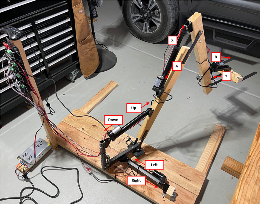
Provided everything was connected as per the instructions, the photo here shows how to control the motions using the 16-Bit Controller (if some motion is backwards, you can fix it by inverting polarity at the Linear Actuator in question).
Check the E-Stop Light

When you power the machine for the first time, the first item to check is that the E-Stop LED light is turned ON. If you push the E-Stop button, the LED light should turn OFF. The E-Stop is a hardware electrical stop and will disable all outputs from the H-Bridges. If the LED is ON, motions are enabled.
Test Motions in Manual Mode


Let’s test our machine in Manual Mode:
Our default screen is in Manual mode, being OFF, and a series of 1’s, which represent motion commands - more on that later, but what you need to know now, is that they should all be 1’s.
If you press the “Start” button in the controller, Manual mode changes to ON, and now motions are enabled. Use the controller to test all the motions.
While testing motions, note the following:
a) Pay attention to your cable routing and verify the cables don’t get damaged/pulled.
b) Some of the 1’s in screen change to 0’s when pressing certain buttons.
c) Actuator motions cannot all occur simultaneously, but in pairs: M0 & M2; M1 & M3. This is a software feature meant to limit current demand.
Calibrating the Potentiometers' Output

Pressing the “Z” button in the controller, will change the Manual mode screen from the 1’s to a series of blocks of numbers as shown below:
Each of those blocks is a number from 000 to 255 representing the input from the Potentiometer Sensors, A0, A1, A2 & A3, respectively. Note the following:
a) The number is an arbitrary number: it doesn’t represent degrees, radians, etc.
b) The number should increase as the related Actuator extends; if the number decreases instead, then flip the connector at the Potentiometer in question.
c) In general, you want the number to change somewhere in the middle of the full 0-255 range. For example, for Actuator M2, you would want the full motion range to be 100 to 160; in other words, you don’t want the input to start at 000 or end at 255, as you could be losing resolution by doing that.
d) Use the instructions in step 51 to calibrate each sensor input to whatever you want.
Once you are done/satisfied with all motions, press the “Start” button to turn OFF the Manual Mode. Note that you can’t switch modes when either Mode is ON.
Inspect Remote Mode


Press the “Mode” button in the Controller to switch to Remote Mode. The Remote Mode screen looks very similar to the Manual Mode screen:
The difference is that the 1’s here represent motion commands being received via Serial communications. The default value is 1’s (no motion is commanded). If you count the 1’s, there’s 14 of them, or 14 bits.
The left-most bit is Bit 13, and the right-most bit is Bit 0. The attached table shows you the Bit and “button press” in the controller they represent.
If you press the “Z” button in the controller, the Remote screen also shows a series of blocks of numbers, but here the first two blocks having a value (255 is default) and the last two blocks are all 000.
The first two blocks represent PWM references for M0 and M1, where 255 is full ON, and 000 is OFF. In this design, only M0 & M1 have the option for PWM regulation, and PWM regulation is only allowed in REMOTE Mode (MANUAL Mode is only full ON/OFF).
Trying Remote Mode
Download the template Arduino Code for Remote mode and write your code. The program is setup so that you only must write your commands, and the rest is done for you. The code can be downloaded by navigating the shared drive folders:
Project A – Robotic Arm > Software > Remote Software
Power the Machine OFF and connect your Arduino to the Control PC Board “Serial 1”. Connect from your Arduino TX to the Serial1 RX, and your Arduino RX to TX in Serial 1. Then power on the machine. This power ON/OFF cycle may be necessary because the machine’s program only sets up for Serial communications at startup.
Note that you still need to use the “Start” button in the 16-Bit Controller to turn the REMOTE Mode ON, and the mode can only be turned ON if there’s a valid input in Serial1. While REMOTE Mode is ON, the machine will follow the commands from your Arduino and its programming. Similarly, the mode can only be turned OFF via the 16-Bit controller. Even if you decode the corresponding bits for “Start” and “Mode” (Bit 1 and Bit 2, respectively), the machine will only accept those inputs from the 16-Bit Controller.
The E-Stop button will be particularly useful while testing/troubleshooting your code. If unintended motion occurs because you did some error in your coding, you can always stop the machine immediately by pressing the E-Stop button: all motions will stop, and the machine will remain static.
If you look at the template code for REMOTE Mode, you will notice a section where the program in your Arduino will process some analog inputs from the machine. These inputs are the values A0, A1, A3 & A3 that the machine processes from the Potentiometer Sensors, and then it shares them with the REMOTE controller. In order words, the machine receives commands, and returns the values for all the Sensors – just in case you wanted to do something in your program with that information.
Machine Capacity and Modifications


Well, if building the machine, and then doing your own programming wasn’t exciting enough, maybe you want to explore the Engineering and do some of your own modifications.
As per the current design and selected Linear Actuators, this machine has a capacity to lift about 10 pounds, with a comfortable safety margin.
The limit of this design is set by the Linear Actuator in position M2. The selected actuators all have a capacity of 1000N, which translates to about 220lbf. There are Linear Actuators with greater capacity available in the market, but they are also more expensive.
The way I confirmed the design was suitable was by measuring the load the Linear Actuator would see in various positions, being M2 the one under the greatest load, followed by M0. I used a weight measuring instrument like the one shown in the photo, the photo shows a reading of 38 lbf when there was no load in the arm. When I put the rated load of 10lb on the forks, the reading increased to around 140 lbf, which still was acceptable given our Linear Actuator capacity.
So, for example, you could substitute the Linear Actuators in positions M2 and M0 for some more expensive units with greater load capacity, and then you would get a stronger robotic arm.
Alternatively, if you look at the design of WA-004 Arm-S, you could increase the 4” distance highlighted in the image here, while keeping the length of the piece and all other dimensions the same, and that would also increase the capacity of the arm, without the need of buying stronger Linear Actuators. Doing this, thought, is not without “costs” namely that the movement range of the arm will be reduced.
Whatever changes you do, make sure you at least check with a measurement scale that you are not exceeding the capacity of your hardware.
Angle Sensor Selection

Now, on using 10K Ohm Potentiometers as angle sensors, you may be thinking “isn’t this a too simple and non-durable solution? Isn’t there some better sensor in the market?”
Yes, indeed, there are some very nice Hall-effect angle sensors out there; the one that I am showing in the picture here also has a 3-wire connection and mimics perfectly the analog voltage output of the potentiometer, so it could be installed in the machine without any electrical modifications (but probably needing new, custom sensor brackets).
However, they also cost over $50 US dollars each, and you would need four of these, so you can do the math and figure why I chose the Potentiometers instead.
Comentary on Software Modifications
The software SA-001 Machine_SW has been tested for all modes and it works well. Software SA-002 Remote_SW, for the part that transmits and receives data from the machine’s Arduino, has also been tested and works well.
The software is open source and the code is there for everyone to see. If you choose to modify the software elsewhere other than the “Write your code here” section of SA-002, you may do so, but at your own risk and on your own accord.
Software betterment is not scope for me on this project, but enthusiasts are free to explore that on their own time; however, please don’t send or post any questions or comments in that regard. In other words, if you change the Machine software code (SA-001) for whatever reason, and the thing doesn’t work anymore afterwards, you are on your own; and if you think you can re-write the code in some way that is more efficient or better, you are welcome to do that, but then also build your own machine and test your code there – I won’t test any software for you.
I am not against progress here, but let’s be respectful of everyone’s scope and time use. There’s probably room for improvement everywhere in this project, but I don’t have any time for keyboard commandos posting “just saying…” opinions online – instead of doing that, build your own machine and let’s see some action!
Conclusion
I hope you liked these instructions and that you will give it a try to this project soon. Thanks for reading!