Project M.I.T.H. - Cheap Cyberpunk Cosplay Helmet
by mith12 in Craft > Costumes & Cosplay
627 Views, 3 Favorites, 0 Comments
Project M.I.T.H. - Cheap Cyberpunk Cosplay Helmet

This is a Military-Inspired Tech Helmet (M.I.T.H.) that draws inspiration from cyberpunk settings. The Helmet is designed to look futuristic while also being functional. This helmet includes an OLED heads-up display that displays information such as temperature and distance. It also has a built-in automatic power-saving functionality via a motion sensor that detects the presence of a user.
M.I.T.H. helmet is designed to provide cosplay enthusiasts an opportunity to create their own futuristic-looking piece for their next costume. Following our instructions is relatively simple and designated to help newer members of the cosplay community to expand their knowledge.
(include a picture of the final product)
helpful tutorials(at timestamps) and resources:
Supplies
Construct the Helmet


All figures referenced appear in the order that they are referenced in the document.
1. To start the helmet construction, the two visors need to be mounted together. Position the top visor on top of the bottom visor. Try to center the visor as much as possible and place a strip of tape to help hold the visor in this position Measure from where the top visor intersects the bottom visor down to the end of the top visor about 2.75”. This is roughly how far the top visor will overlap the bottom. See figure 1 below for an example.
2. Place another piece of tape to hold the visor at the 2.75” overlap so it holds itself in place. With the visors still overlapping, roughly estimate 3/8” down from the top edge of the bottom visor and mark the spot with a marker. Using a No. 44 drill bit put a drill a hole through the taped together visors, so the holes lineup. It helps at this point to use a piece of tape as a reference line to keep the second hole on the other side of the visor as a straight in line with the first as possible. After this drill the second hole. You can now remove the tape holding the two visors together.
3. On the bottom visor, the heat set inserts will be mounted. The example depicted in the images uses M1.6 heat set inserts, but we found that the hardware is so small that it makes it difficult to thread in the screws. While we were successful using the M1.6, you may find it easier to use M3 heat set inserts and screws. If you elect to use M3 hardware you will need to use a No. 21 drill bit, we recommend using the M3 hardware since it will also be used later.
4. To attach the heat set inserts, you will use a soldering iron. Turn on the soldering iron and turn it up to a manageable temperature; start at 200°C. The visors are very thin, so you have to be careful not to push the heat set insert all the way through the plastic. Place the heat set insert over the drilled hole on the bottom visor. Place the soldering iron along the top of the heat set insert as seen in figure 2.
5. Though it may be tempting to not put the tip of the iron in the threaded hole of the heat set insert. Sometimes the heat set insert will get stuck on the tip of the iron and you won’t be able to get it off. As the heat set insert heats up it will melt the plastic of the visor surrounding the heat set inserts. Push the insert down until the plastic reaches one of the two rows of ridges depicted in figure 3.
6. Once the heat set inset reaches this depth, remove the soldering iron from the top of the heat sent insert and let the insert and plastic cool down to solidify the bond. Repeat the same procedure for the hole on the opposite side. After both sides have cooled place the top visor over the bottom visor that now has the heat set inserts. Lineup the holes of the top visor with the inserts and thread in the screw.
7. Before we mount the visors to the facemask, we will need to do some work on the facemask. The facemask is two separate pieces, the goggles and the plastic mask itself. The goggles have a tendency to fall off the mask, so the two will have to be glued together. Note where the plastic mask touches the goggles, since these will be the locations the contact cement will be placed to adhere them together.
Some things to note about contact cement:
- Be in a well-ventilated space as the contact cement fumes are toxic
- Wear gloves… this is super important, I accidently glued my fingernail to the tip of my finger, not fun ☹ also witnessed this stuff melt Styrofoam while wet, so wear gloves!
- Close the lid when not in use, the longer the can is open the thicker the glue gets, if it gets too thick you will need to get a thinner to make it easy to apply again
- Apply contact cement to both pieces that will be glued together, and let the glue sit on each piece for 5 minutes before sticking them together. The glue will lose some of its sheen at this point, which is a tell tale sign the pieces can stuck together.
With these details in mind, brush the contact cement on the locations where the goggles and plastic mask meet. Wait five minutes and place the two pieces together and let them sit. After the pieces dry move onto the next steps.
8. Next, these visors will mount the face mask seen in figure 5. For ease of integration, remove the top visor from the bottom visor. The bottom visor will mount to the facemask. Notice that the front of the face masks has two indentations on either side of the bottom of the mask. At the corner of the indentations the mask raises back up. At the top of these corners is where the second set of heat set inserts will be placed to mount the visors to the face mask. Figure 6 shows the inside of of the mask where the heat set inserts will be placed.
9. Once again lineup the visors with these locations on the face mask and tape the visors in place so that they are centered on the face mask as seen in figure 7. The corner of the bottom of the visors is a curved edge . Using a marker, dot the center of this radius to mark where the holes will go. Using the No. 21 drill bit associated with the M3 hardware drill through the visor and the face mask while the two are still taped together.
10. Turn on the soldering iron again and position the heat set inserts over the holes created on the face mask. Gently press the heat set inserts into these holes until the plastic of the face mask reaches one of the two rows of ridges as before. Once again let the heat set insert and the plastic cool before threading in screws.. After everything has cooled mount the bottom visor to the face mask, and then mount the top visor to the bottom visor as done in the previous paragraph.
*Note do not overtighten the screws as this may dislodge the heat set insert from the plastic.*
11. With the previous steps completed, it is now time to mess with the EVA foam. First, the side blinders will be ‘mounted onto the bottom visor and face mask. The results of this step will produce the look seen in figure 8. To get this shape use the stencil outline in the document above labeled A. This file can be found at the bottom of the "Construct the Helmet" section or at the top of the page . Print out this stencil and cut the shape labeled A out of paper and trace it on the EVA foam.
12. Using either a X-Acto blade or a box cutter (utility knife) cut out two of these shapes. For EVA foam this thick (10mm) it is easier to use a box cutting knife, but the X-Acto knife is better at cutting curves though it may take a few passes to get all the way throw the foam. Once these shapes are cut out use a heat gun to heat up the foam.
Disclaimer: The temperature of the air coming out of the heat gun is in excess of 100°C and it can cause serious burns if care is not taken.
13. To avoid injury, it is easiest to put the X-Acto knife in one end of the foam piece and hold the foam over the heat gun like in figure 9, while holding the handle of the knife. Once the foam is heated up, remove the foam from over top of the heat gun and remove the knife. While the piece of foam is still warm, bend the foam over your wrist. It is worth noting that you do not have to use your wrist to form the foam, any curved surface will do. This is a trial-and-error process. The goal is to get the foam to match the curvature of the visor to the best of your ability. This will make it easier to glue.
14. After you are happy with the shape of the piece it is ready to glue onto the facemask/visor. The foam will be glued in three places. Two of which are on the visor and one on the edge of the goggles. Figure 10 depicts these locations. Brush the contact cement onto the visor/mask and on the corresponding locations on the EVA foam piece. Wait 5 minutes and then press the EVA foam onto the visor/mask and let it dry. Then repeat the same steps for the other side.
15. Next the EVA foam crown will be built on the top visor. Using the stencil outline labeled B, cut out the stencil and trace it onto the EVA foam. Cut two of these pieces and glue the long straight side of these pieces together as seen in figure 11. Brush contact cement onto both straight edges and wait 5 minutes before pressing together.
16. After this has dried place the EVA foam crown along the top of the top visor to see how it will fit . Make necessary cuts of adjustments as needed to get it flush with this rim. If the curve isn’t exactly lined up, you can remedy this by using the heat gun to help form the crown to the right curve.
17. After you are happy with the shape, apply contact cement to the flat rim on the top of the visor and on the corresponding side of the EVA foam crown. Wait 5 minutes and then press together. The finished product should resemble figure 12
18. Next the electronic box will be constructed on the strap of the mask at the back of the helmet. The electronics box is composed of 6 pieces. The dimensions for the box can be seen below.
Dimensions:
Front (removable lid w/distance sensor holes)- height: 3.5” width 3.375”
Back(sits on the back of the head)- height: 3.5” width 3.375”
Left/Right Sides – height 2.75” width 3.5”
Left/Right Sides cutout for strap – width: 1.5” height 0.75”
Top/Bottom dimensions – width: 3.375” height: 1.75”
All the pieces will be glued together as seen in figure 13, 14, 15, and 16. The front piece which acts as the lid to the electronic box is not glued. Instead 3M Velcro strips are used to attach the lid to the rest of the constructed box. Start building the box by cutting out the back piece first. Then the top and bottom sides.
19. Glue the top and bottom sides onto the surface of the back piece so that the edge of the back piece is flush with the outer side of the side pieces. After these pieces are dry, cut out the left and right side pieces from the EVA foam.
20. Then cut the slots that the head strap will go through. These slots will be centered on these pieces and will be on the back edge of the left and right sides of the box. See figure 15 for more detail. Apply contact cement to the edges of the top, bottom, and back edges with an exception of the spot where the slot is. Then apply contact cement to the corresponding sides of the left and right pieces. When it is time to put the pieces together make sure the head strap runs through the slot cutouts. Once it is glued you will not be able to put the head strap through the slots.
21. Attach the pieces and the glue dry. The last piece that needs to be attached is the front. Before you attach the 3M strips, take the SR04 ultrasonic distance sensor and position it so it is centered on the piece where the top of the cylinders are pressed on the EVA foam. Trace these circles and cut out the holes as seen in figure 16.
22. Now take two Velcro strips and trim them so the fit flush on the edges of the top and bottom pieces as seen in figure 17. Peel back the plastic covering the adhesive and adhere the strip to the edges of the top and bottom side edges. Press firmly to ensure they stick. Attach two more strips to the corresponding side of the Front piece and once again press firmly to ensure they adhere properly. This completes the electronic box.
23. Next the electronics will be mounted inside the box using the rest of the Velcro strips. The distance sensor will be pressure fit into the holes that were cutout in the previous steps. Place the distance sensor cylinders in the holes so the pins face up. The front of the electronic box will resemble figure 18.
24. The battery will be mounted behind the distance sensor on the bottom piece of the box. Place a Velcro strip on the bottom piece and another on the battery itself. Place another Velcro strip on the other side of the batter and one more on the bottom of the Arduino Nano Every. This will mount the Arduino to the battery and the battery will be mounted to the electronic box.
25. The Infrared proximity sensor will be mounted to the top left corner of the electronics box close to the front of the box (distance sensor side) with the white dome facing the back piece of the electronic box. Since there is not a lot of real estate to put a Velcro strip, a piece of EVA foam will be glued on the side of the Infrared distance sensor opposite to the adjustable sensitivity screw terminals. Cut a piece of EVA foam wide enough to place a Velcro strip on one side of it. See figure 19 and 20.
26. Brush a thin layer contact cement on the flat portions of the Infrared proximity sensor. Then brush contact cement on the corresponding side of the EVA foam piece that was just cutout. Wait 5 minutes and then press the two together and let them dry. Now put a Velcro strip cut to the length of the width of the proximity sensor on the EVA foam. Put another Velcro strip with the same length on the top left corner of the electronic box on the left side as seen in figure 21. This takes care of the mounting of the infrared proximity sensor, battery, Arduino, and distance sensor. The finished mounting will look like figure 22.
27. The OLED screen will be mounted to the top center of the bottom visor using another Velcro strip cut to the length width of the OLED screen seen in figure 23. Make sure the pins that the Arduino connects on the OLED screen are on top when mounting. The LEDs will be glued in place using contact cement, and they will be glued behind the silver meshes seen the bottom of the plastic mask seen in figure 24. It is important to note that the wire loom steps below should be completed as this will make it easier to solder the wires for these components to the OLED and LEDs.
28. Now it is time to get the plastic wire looms cut that will contain the wire going from the electronic box to the front of the helmet. Cut two 18” pieces from the 10ft length. Note this length can vary depending on how much you need the straps to stretch to fit your head. 18” gives the plastic sheathes plenty of excess length to allow the elastic band to stretch to a reasonable degree, but you may shorten or extend this length as needed.
29. With these two strips cut, run seven 3ft long wires through the right wire loom (4 for the OLED and 3 for the right LED) and three 3ft long wires through the left sheath (3 for the left LED). This is a good point to solder the wires for the LEDs to the LEDs.
30. The wires that will connect to the OLED screen and LEDs at the front of the helmet to the electronic box will travel through plastic sheathing. One end of the plastic sheathing will go through the cutout for the head strap on the electronic box. It protrudes into the box about 1/2” and it will be glued using contact cement inside of the electronic box on the back piece of the box. See figure 25.
31. Two plastic sheathes will go the the front of the helmet. One on the left side and one on the right side. The right sheath will contain the OLED wires and the right-side LED wires. The left sheath will contain the left side LED wires. These sheathes will connect on their corresponding side of the helmet on the foam crown the protrudes down from the top visor. Figure 26 depicts this.
32. With that done make a hole in the EVA foam crown that attaches to the top visor that is just large enough for the plastic sheath to squeeze through. Put a thin layer of contact cement on the outside of the sheathe and on the inside of the holes in the EVA foam. DO NOT WAIT 5 MINUTES for this. While the glue is still wet run the wires through the hole and then push the sheath through the foam; DO NOT PULL THE WIRES OUT OF THE SHEATH. Make sure all the wires are present on the front end and back end of the plastic sheath. Do this for both left and right sides Once the front of the sheathe is flush with the inside of the EVA foam crown stop pushing. Then glue the other side of the plastic sheath as detailed in the prior paragraphs.
33. Now solder the wires for the OLED screen to the OLED screen. Make sure the wires are color coded so that the function of each wire is distinguishable on either end of the the wire loom.
34. The final product should look like figure 27. Though it is not required, you can use a Dremel/ rotary tool with a sanding cylinder or a piece of sandpaper, to clean up the edges of the EVA foam pieces. Feel free to soften these edges of put chamfers on pieces of EVA foam to your liking.
Downloads
Wiring Up the Nano

An understanding of how to solder is required for making this circuit. If you need help soldering, refer to the provided soldering tutorial above.
First connection is for powering the Arduino. To accomplish this, you must solder two header pins that come with the Arduino nano every to the Vin and GND input. The battery’s red wire will go to Vin, and the black wire to GND. Next, you must hook up the Motion Sensor (HC-SR501). To do this, solder the 5V Arduino pin to the VCC motion sensor pin. Next, solder the motion sensor’s output pin to the Arduino’s D4 pin. Lastly, solder the GND pins together. For this project, it may be easiest to solder 1 wire from the Arduino’s GND pin to the GND wires of multiple devices. The motion sensor will periodically check for motion. If it does not detect motion for a while, it will cut the power to the other devices to save battery life. The next step is setting up the distance sensor (HC-SR04). First, solder VCC to the Arduino’s D12 pin, and GND to GND. Next, solder Echo to D2 and Trig to D3. The Arduino will send a pulse to trig when it is ready to measure, and the echo pin will send a pulse back that the Arduino can convert to distance. The last sensor to be soldered is the temperature sensor (LM34). Once again, VCC must be soldered to D12 and GND to GND. The output pin must be soldered to the Arduino’s A0 pin. The temperature sensor will measure the temperature and send the information to the Arduino using an analog voltage level to represent the temperature. Next, the OLED Display (SH1106) must be soldered. To power it, VCC must be soldered to the Arduino’s 3.3V pin, and GND TO GND again. For the Arduino to communicate with the display, SDA must be soldered to A4, and SCL must be soldered to A5. The OLED Display will be used for displaying the distance and temperature measurements to the user. Lastly, the LEDs must be soldered. For this project, Team 12 has decided to use purple blinking lights using one signal to control both red and blue. This is done by soldering 2 resistors (Team 12 used 220Ω, but the value can change based on the user’s desired brightness, as long as the resulting current is within the LED's limits) to the Arduino’s D6 pin. From there, each resistor will go into the red and blue pins of the RGB LED. Lastly, because Team 12 is using common cathode RGB LEDs, the cathode pin needs to be soldered to the Arduino’s GND.
Upload Code
Download the provided code (at the top of the page or below this step) and download Arduino IDE Program
Open the main_code.ino file in Arduino IDE
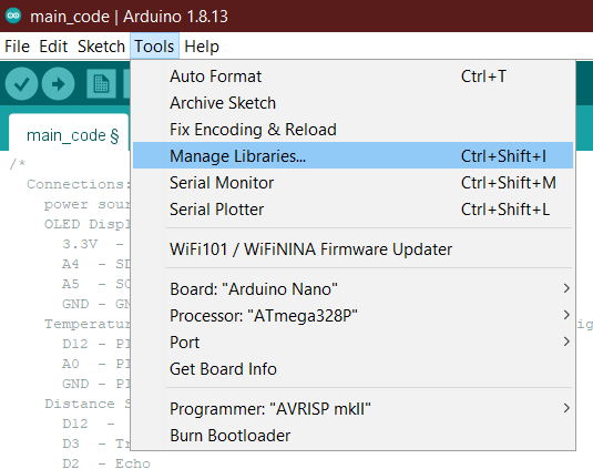
Click on TOOLS and MANAGE LIBRARIES
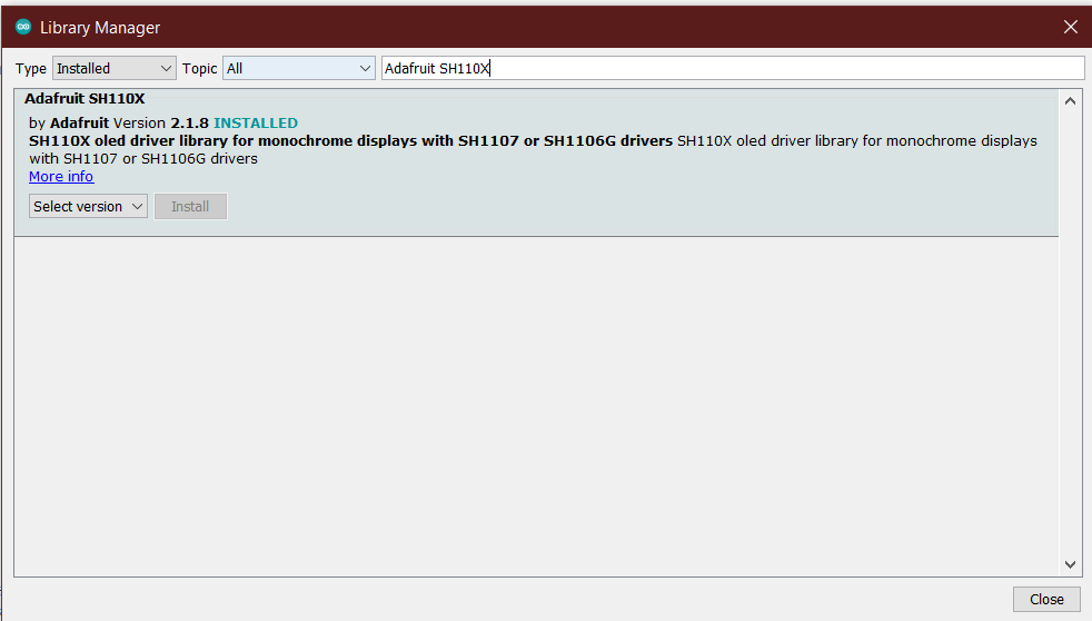
In the search bar, search for “Adafruit SH110X” and install the library
Select the Arduino Nano Every under “TOOLS”
If you don't see the nano every, select Boards Manager and search for and install "Arduino megaAVR Boards"
With the Arduino Nano plugged in, select the appropriate COM port
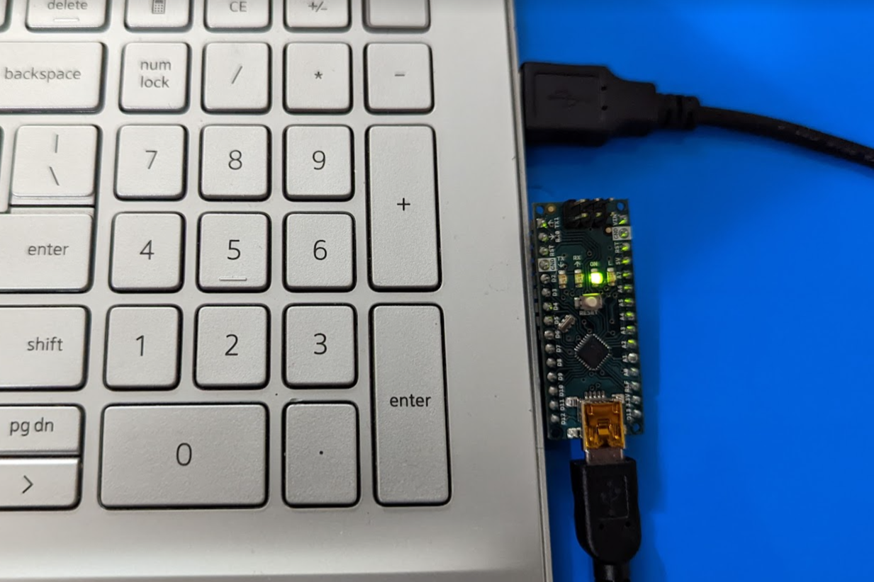
The correct port will the be the new port that shows up after plugging in the Arduino
Without Arduino plugged in

With Arduino plugged in:

After making all the appropriate pin connections according to the block diagram upload the code by
Pressing the arrow at the top left 