Programming ESP32-CAM With ESP8266
by Svilen Grigorov in Circuits > Cameras
54533 Views, 16 Favorites, 0 Comments
Programming ESP32-CAM With ESP8266

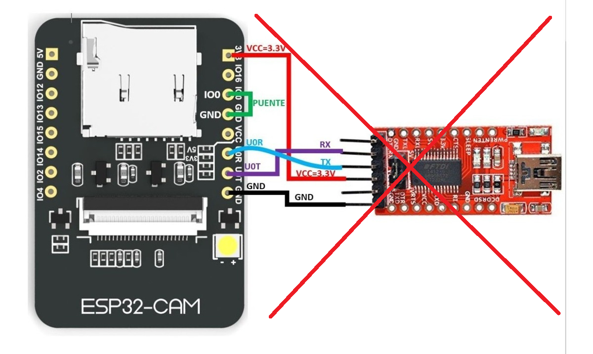
So here is the situation. You have ordered an ESP8266 and excited about the possibility of having an ESP32 with a camera for less than 10$ you have added the ESP32-CAM to your basket. Now your order has just been delivered and everything is just fine. Except it's not. In your excitement you overlooked the fact that the ESP32-CAM does not have a USB port and you need a FTDI programmer to program it. Unfortunately you don't have a FTDI programmer at hand. So what can you do? If you are like me and you hate waiting, you can always use your ESP8266 board to do the trick.
Connecting the Pins

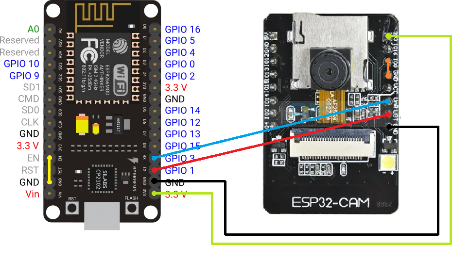
First of all, we connect the Enable pin (labeled "EN") of the ESP8266 to the ground (labeled "GND") as shown by the yellow connection. This keeps the ESP8266 from turning on.
Then we connect the RX, TX, 3V3 and GND from the ESP8266 to the ESP32-CAM.
Note that unlike using a FTDI programmer where we swap RX and TX, here we connect the ESP8266 TX to the ESP32-CAM TX (as denoted by the red connection) and the ESP8266 RX to the ESP32-CAM RX (as denoted by the blue connection).
Important: To be able to upload code to the ESP32-CAM and not just communicate with it, you have to connect GPIO0 on the ESP32-CAM to the GND on the board (as denoted by the orange connection).
Testing With an Example From the Arduino-esp32 Library


Note: As a prerequisite to this step you need to have Arduino IDE installed as well as the ESP32 add-on.
After you've successfully connected all the pins from the first step it's time to plug the USB cable into the ESP8266 and into your PC.
First, you have to locate which port is the serial connection to the ESP8266, and by extension the ESP32-CAM, established on. Then go to Tools > Port in the Arduino IDE and select that port.
You also have to choose a board by selecting Tools > Board > ....
Most Chinese ESP32-CAM boards correspond to "AI Thinker ESP32-CAM" but yours may be different so make sure you select the right option here.
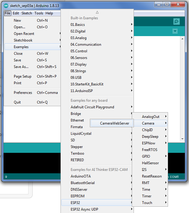
Now let's open an example from the esp32 library. To do this go to File > Examples > ESP32. There my favorite example (and the most impressive one) is the Camera > CameraWebServer.
After the example has opened locate the line where it says "Select camera model". There you should comment all models except the one that comes with your ESP32-CAM. Again on most Chinese ESP32-CAM boards with OV2640 camera that is the line:
#define CAMERA_MODEL_AI_THINKER<br>
Then you should change the lines
const char* ssid = "*********";
const char* password = "*********";
to contain the ssid and password for your Wi-Fi.
After that upload the code to your board by clicking the Upload button (looks like a right arrow). Don't worry if the compiling is taking a lot of time. After compiling you should see output from esptool.py printed in red showing that connection was established and if everything is alright showing upload progress.
After you see the lines
Leaving...
Hard resetting via RTS pin...
you can safely remove the connection between GPIO0 and GND on the ESP32-CAM to exit writing (uploading) mode so that you can run your code and communicate freely using the serial connection through the ESP8266.
Use Tools > Serial Monitor to open the serial monitor in Arduino IDE. Set the baud rate to 115200 baud on the dropdown next to the "Clear output" button, then push the RST button on your ESP32-CAM. You should see some output from your board and after a few seconds something similar to
WiFi connected
Starting web server on port: '80'
Starting stream server on port: '81'
Camera Ready! Use 'http://192.168.100.7' to connect
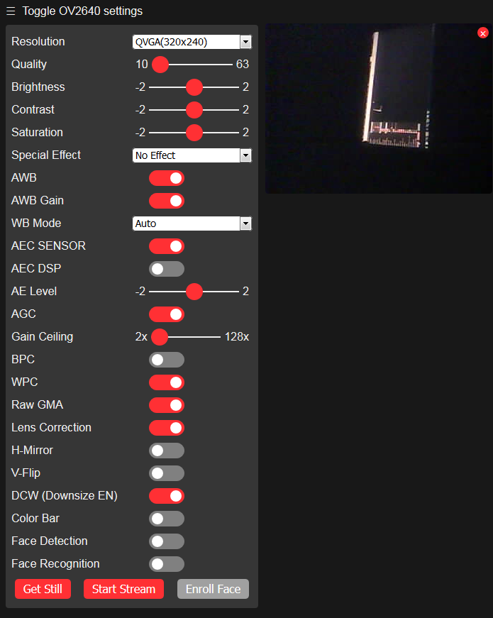
should be printed on the serial monitor window. Then just open the link in any modern browser and enjoy your ESP32-CAM Video Streaming Server :).