Program ESP01 Using FTDI
by Manodeep in Circuits > Microcontrollers
30012 Views, 11 Favorites, 0 Comments
Program ESP01 Using FTDI
The ESP8266 is the microcontroller chip that is used on the ESP-01 module/microcontroller board. The chip has at least two different boot modes: ‘normal mode’ and ‘programming mode’. ‘Programming’ (or ‘flashing’) refers to uploading any (custom or default) software (or firmware) to the ESP8266’s flash memory.
Flashing will overwrite the previous programming/firmware (including the AT command set if that was flashed). The breadboard setup in this post will allow booting into programming mode which will allow a module to be flashed with new firmware. To be able to flash new firmware onto an ESP-01 module, it needs to be connected to a programming device containing a copy of the firmware (e.g. a PC). An FTDI USB to TTL serial converter module will be used as a communication module.
Supplies
1. ESP01
2. FTDI USB to TTTL serial converter mo
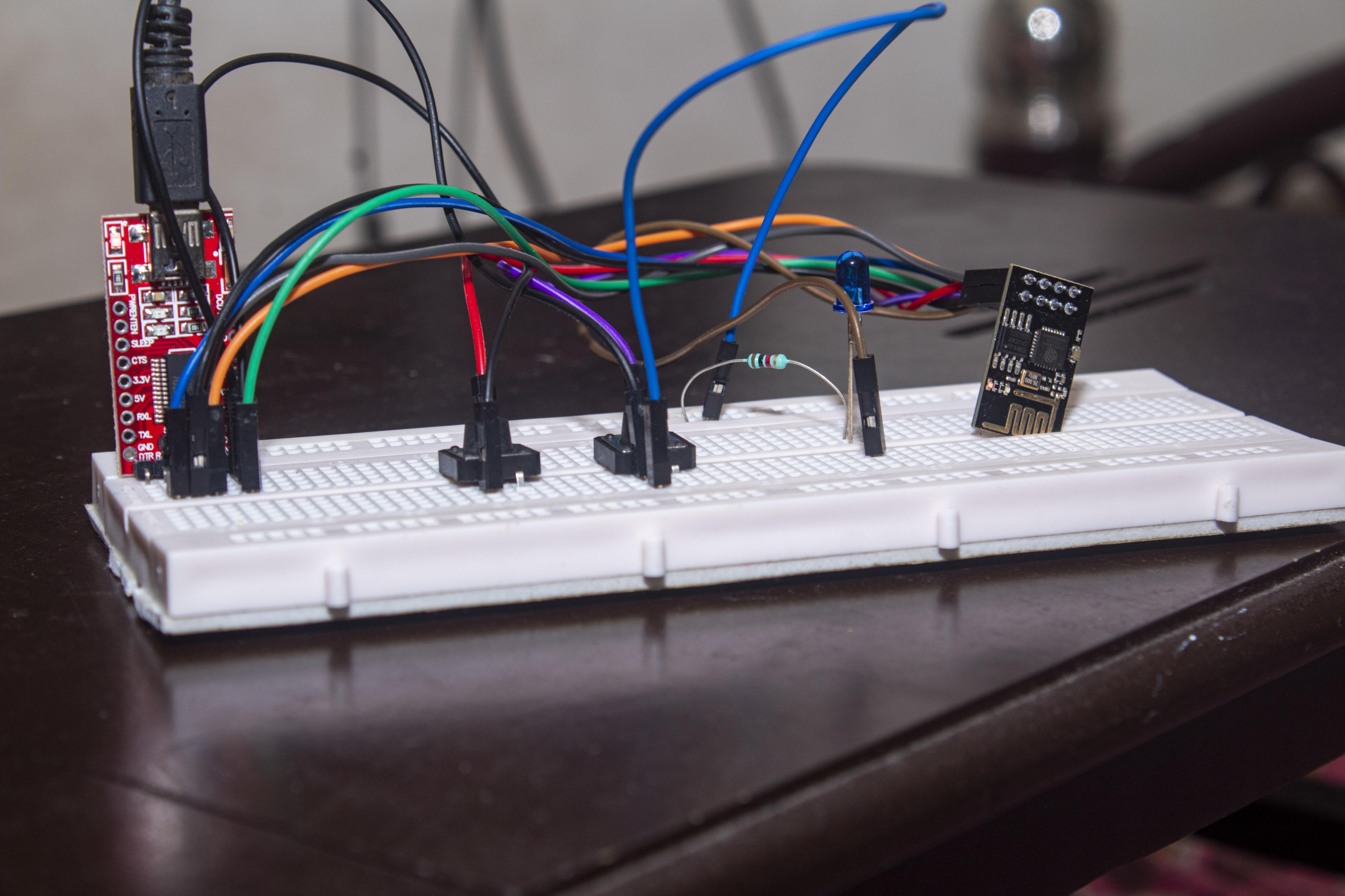
Connect FTDI With ESP01 According to the Diagram Given Here.
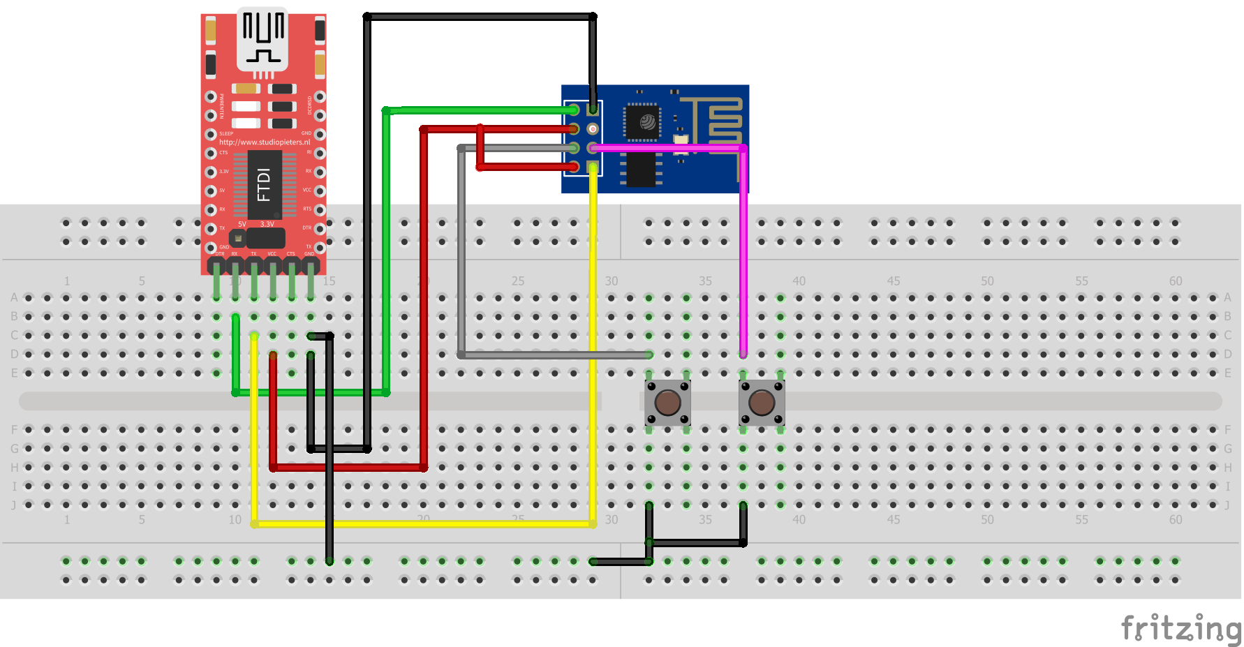
Note - FTDI should be in 3.3v mode.
Before Uploading the Code.
Before uploading the code, press and hold RST button then press GPIO0 button while holding RST button. Then leave RST button then leave GPIO0 button. ESP01 will go into programming mode now.
Upload the Code.
#include <ESP8266WiFi.h>
#include <WiFiClient.h>
#include <ESP8266WebServer.h>
#include <ESP8266mDNS.h>

ESP8266WebServer Webserver(80);

// Replace with your network credentials
const char* ssid = "xxxxx";
const char* password = "xxxxxx";

String HTMLpage = "";
int LED = 2;

void setup(void) {
  HTMLpage += "<head><title>Webserver Tutorial</title></head><h3>ESP8266 Webserver Demo (Toggle LED)</h3><p>LED <a href=\"ledON\"><button>ON</button></a> <a href=\"ledOFF\"><button>OFF</button></a></p>";

  pinMode(LED, OUTPUT);
  digitalWrite(LED, LOW);
  Serial.begin(115200);
  WiFi.begin(ssid, password);
  Serial.println("");

  // Wait for connection
  while (WiFi.status() != WL_CONNECTED) {
    delay(500);
    Serial.print(".");
  }
  Serial.println("");
  Serial.print("Connected to ");
  Serial.println(ssid);
  Serial.print("IP address: ");
  Serial.println(WiFi.localIP());

  if (MDNS.begin("esp8266", WiFi.localIP())) {
    Serial.println("MDNS responder started");
  }

  Webserver.on("/", []() {
    Webserver.send(200, "text/html", HTMLpage);
  });
  Webserver.on("/ledON", []() {
    Webserver.send(200, "text/html", HTMLpage + "<p>LED is ON</p>");
    digitalWrite(LED, HIGH);
    delay(1000);
  });
  Webserver.on("/ledOFF", []() {
    Webserver.send(200, "text/html", HTMLpage + "<p>LED is OFF</p>");
    digitalWrite(LED, LOW);
    delay(1000);
  });

  Webserver.begin();
  Serial.println("HTTP Webserver started");
}

void loop(void) {
  Webserver.handleClient();
}Output
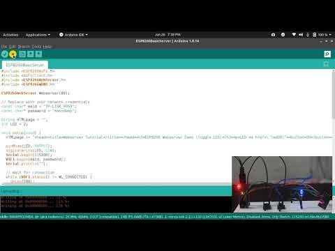
You'll see that ESP01 is connecting to the WiFi network. It will provide an IP address . Copy and paste it to the web browser. Connect an LED to GPIO2. You can now control the LED using the web interface.