Product Partial Repair Using Controlled Destruction
by design4repair2021 in Workshop > Repair
860 Views, 2 Favorites, 0 Comments
Product Partial Repair Using Controlled Destruction


Do you have a broken product part that seems salvageable and do you want to try to do this yourself? That is great, because this guide will help you save your product!
What is the strategy?
The method used in this manual explains how you can use your 3D printer to repair gaps in your product parts by filling them back up with a printed insert. It uses one specific strategy that you can work with, to design and manufacture an insert for any broken product part! Once the insert is completed and placed in the gap, your product should be ready to use again.
In what cases is this method applicable?
As stated above, this manual provides guidance on how to use 3D printing to repair a fracture. But besides fixing a partially broken part (with gaps), this strategy may also be used to fix a fractured part by reinforcing it.
How is the strategy explained?
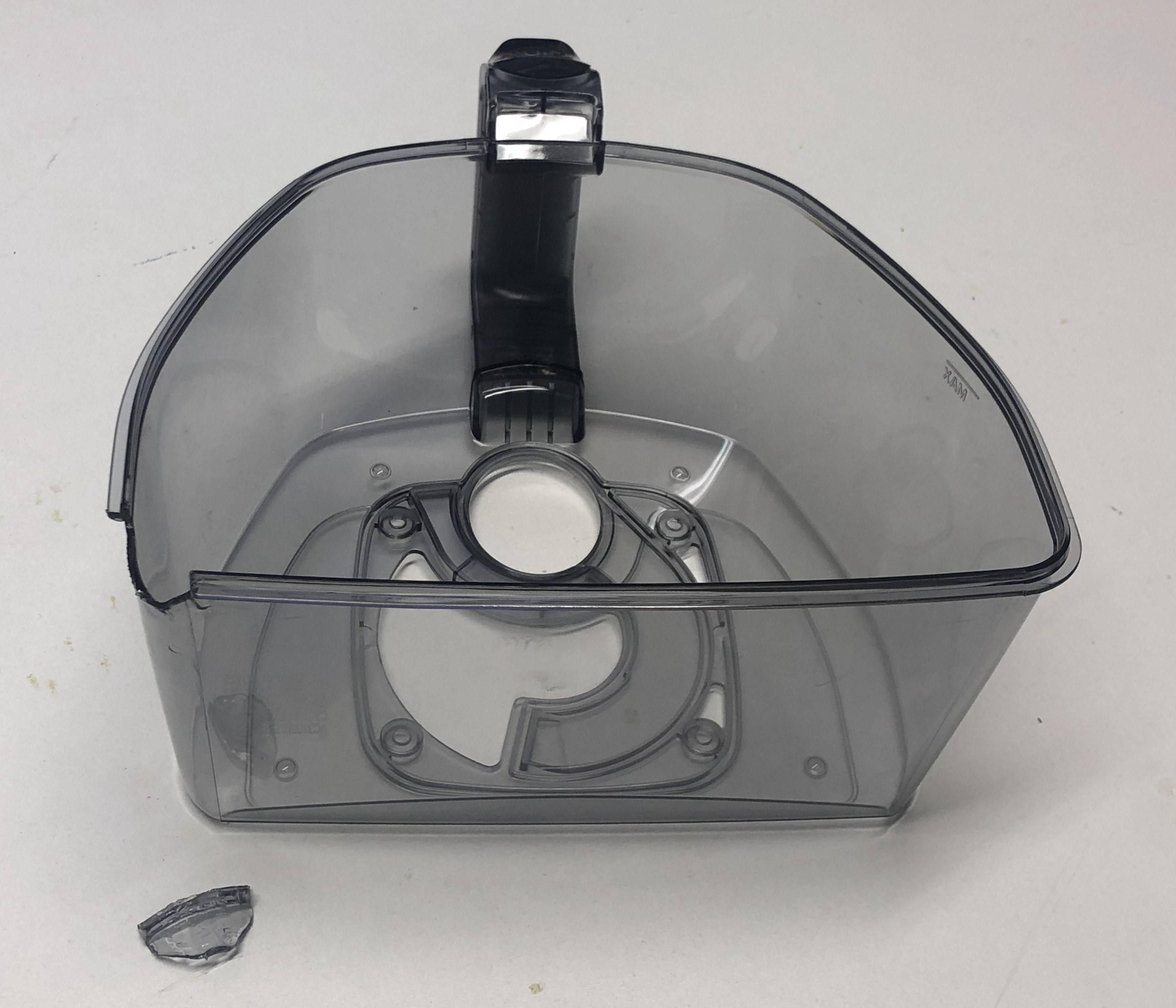
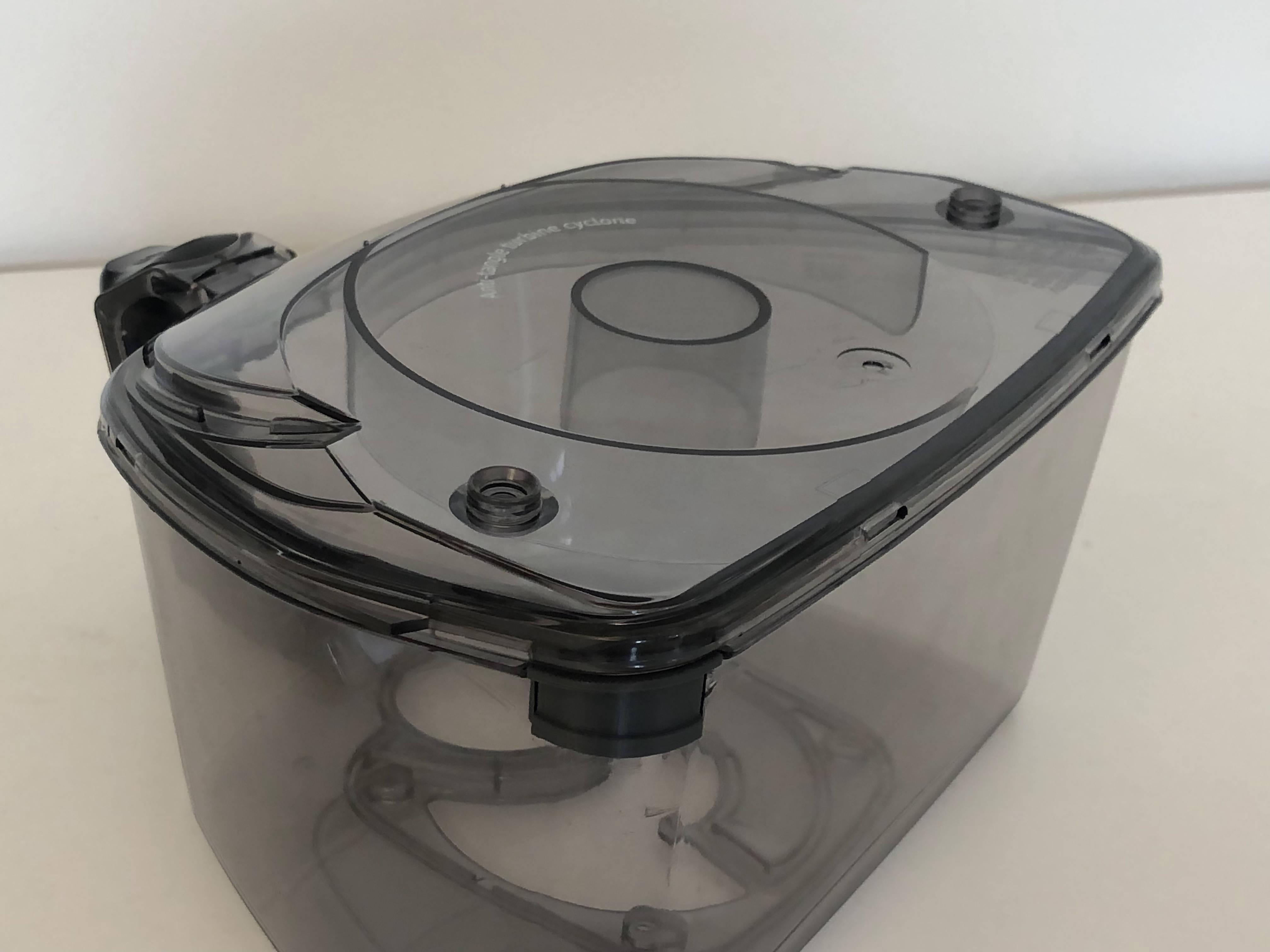
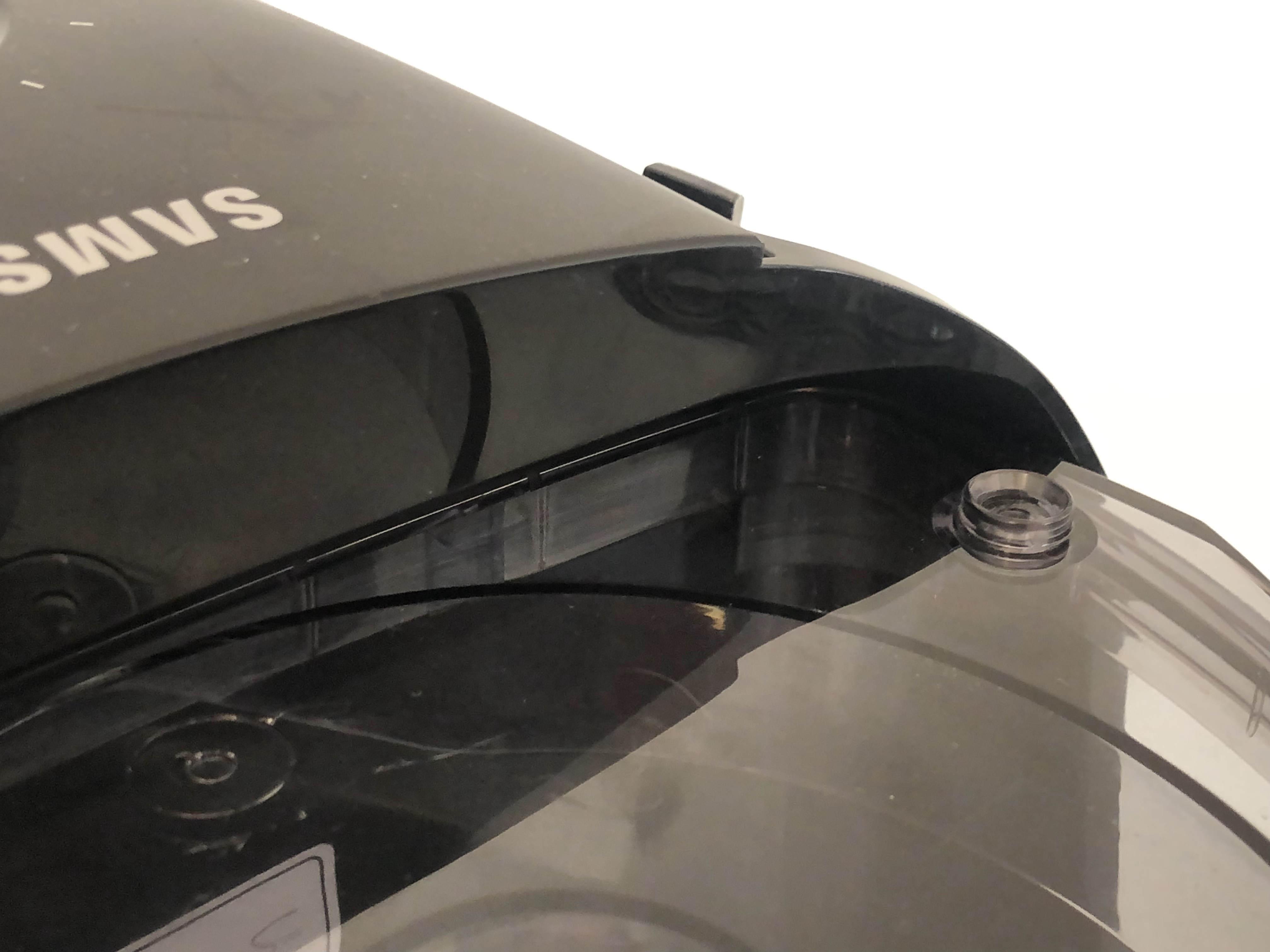
In this example case study a broken dust-container from a Samsung VC07M3130V1 vacuum cleaner will be repaired by replacing the missing material at the gap, making sure that the part will be functional again. The steps taken for this repair can be used on any type of product, so this case study is solely an example of how to use the strategy!
DISCLAIMER:
This project requires you to take apart your product and to tinker with it. This will cause any warranty on the product to be void. Please approach this safely and if you're not sure, ask an expert.
ALWAYS unplug the product when taking it apart and reassembling it. If the product is hot, let it cool down first.
We and any other linked resources do not hold any responsibility for anything that you do while following this guide.
Supplies

Please read the master page for supply details!
Tools
- 3D printer
- CAD software
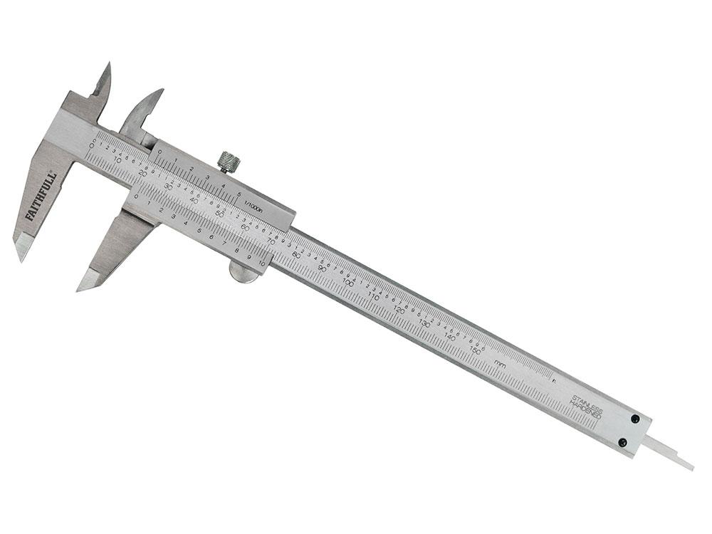
- Calliper
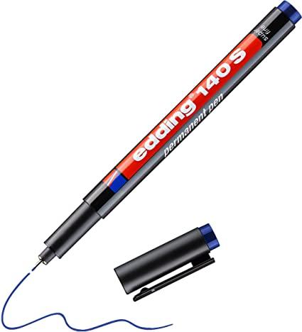
- Permanent pen
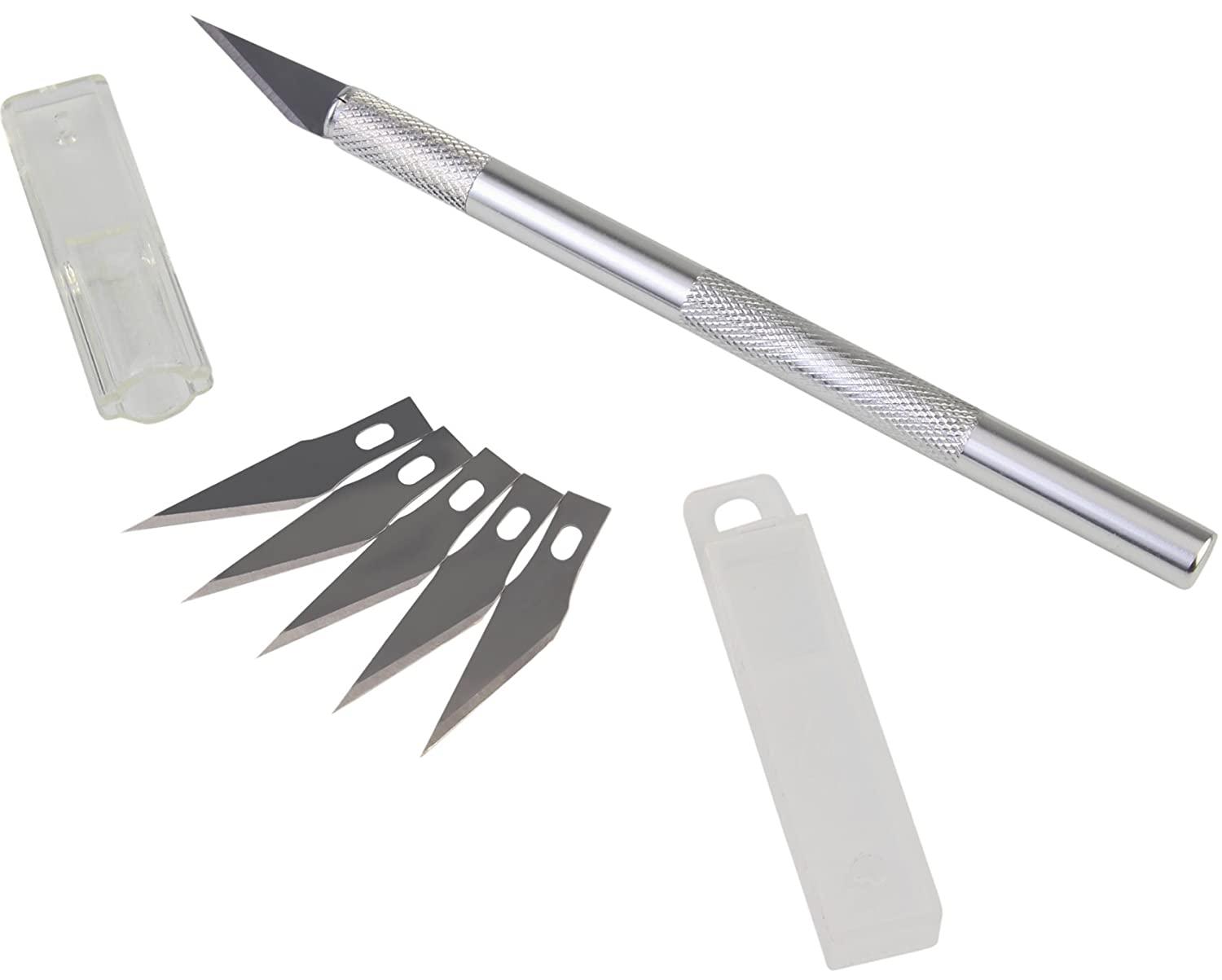
- Precision knife
- Slicer software
Materials
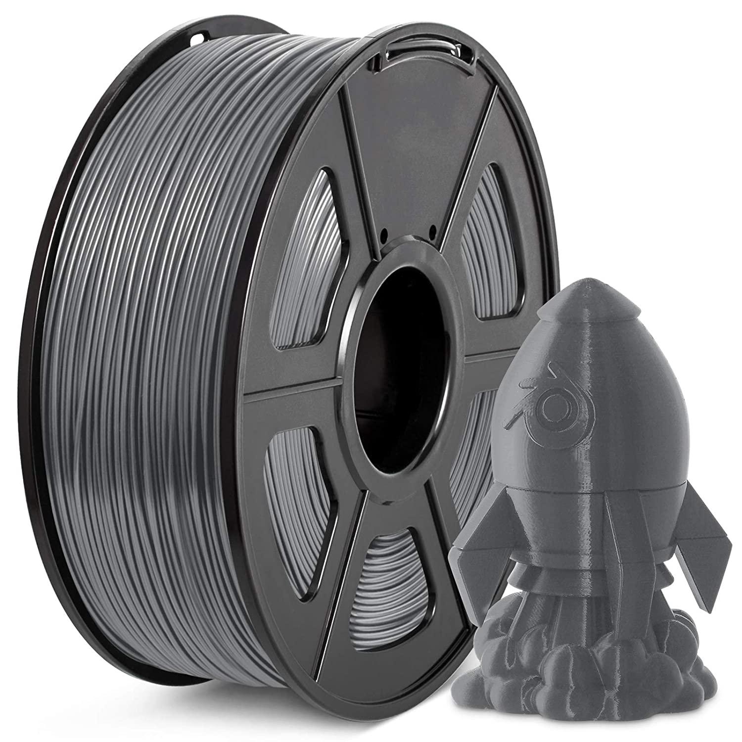
- PLA filament (other materials possible)
This strategy is tested for SolidWorks, but should work with most available CAD software, as there are no specific requirements, such as the possibility for parametric design.
The slicer software used in this case study is Cura. Again, most available software should work, but only Cura has been tested.
This strategy has been tested on the Ender 3 and Ender 3 Pro, but should work with most available 3D printers. Keep in mind that this method often uses very small prints with tiny detail. The tests were executed with a 0.4mm nozzle.
The printed inserts for this method are often very small, meaning that tolerancing is a very important aspect. A calliper is therefore highly recommended if you want to be successful in following this strategy. Using a regular ruler is possible, but keep in mind that this method may not provide as accurate measurements and make the process a slower. The actual tolerances can range from about 0.1 - 0.4mm, depending on your printer settings and therefore, if you are not that aquinted with using callipers, preferably use a digital one.
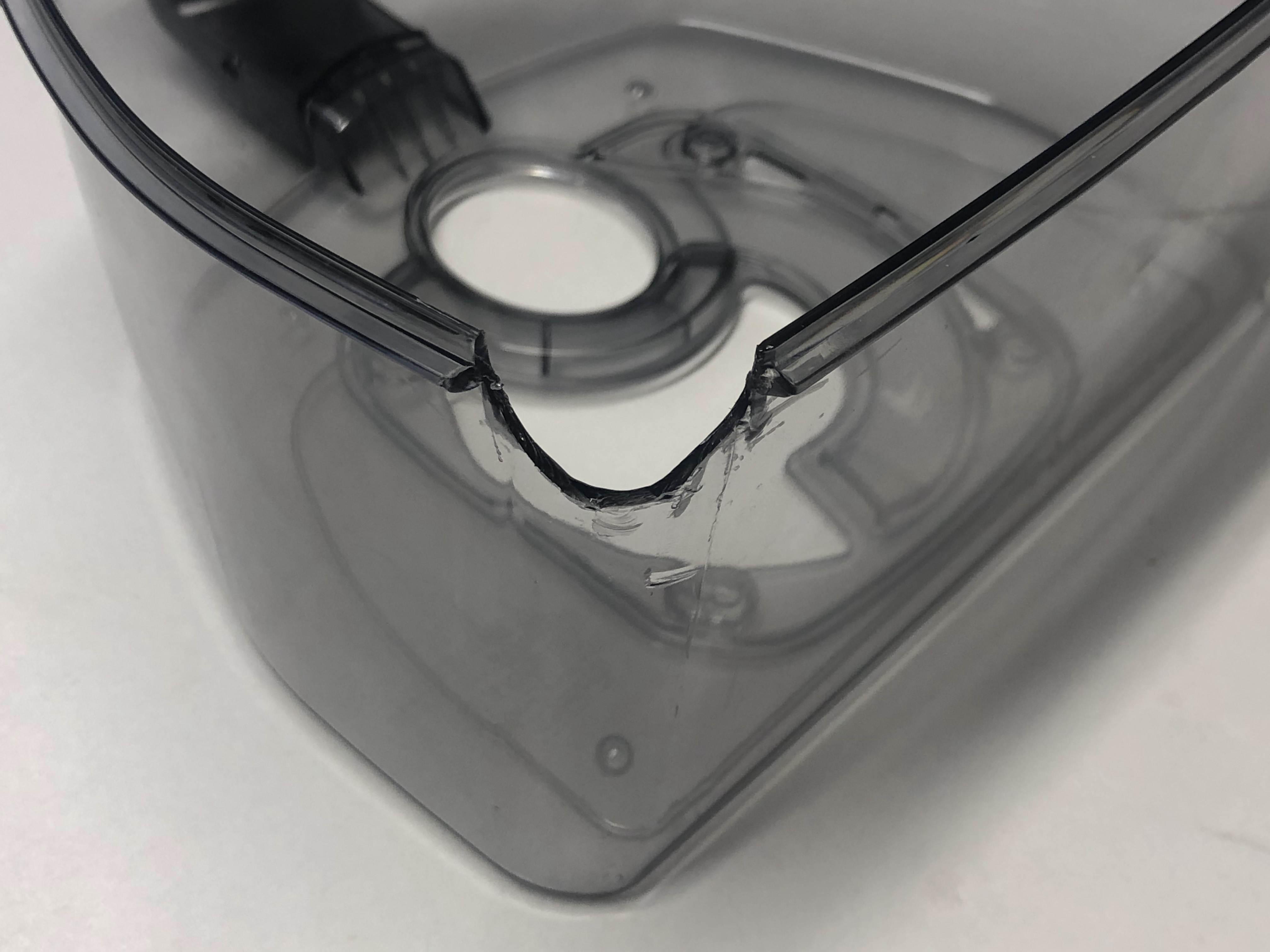
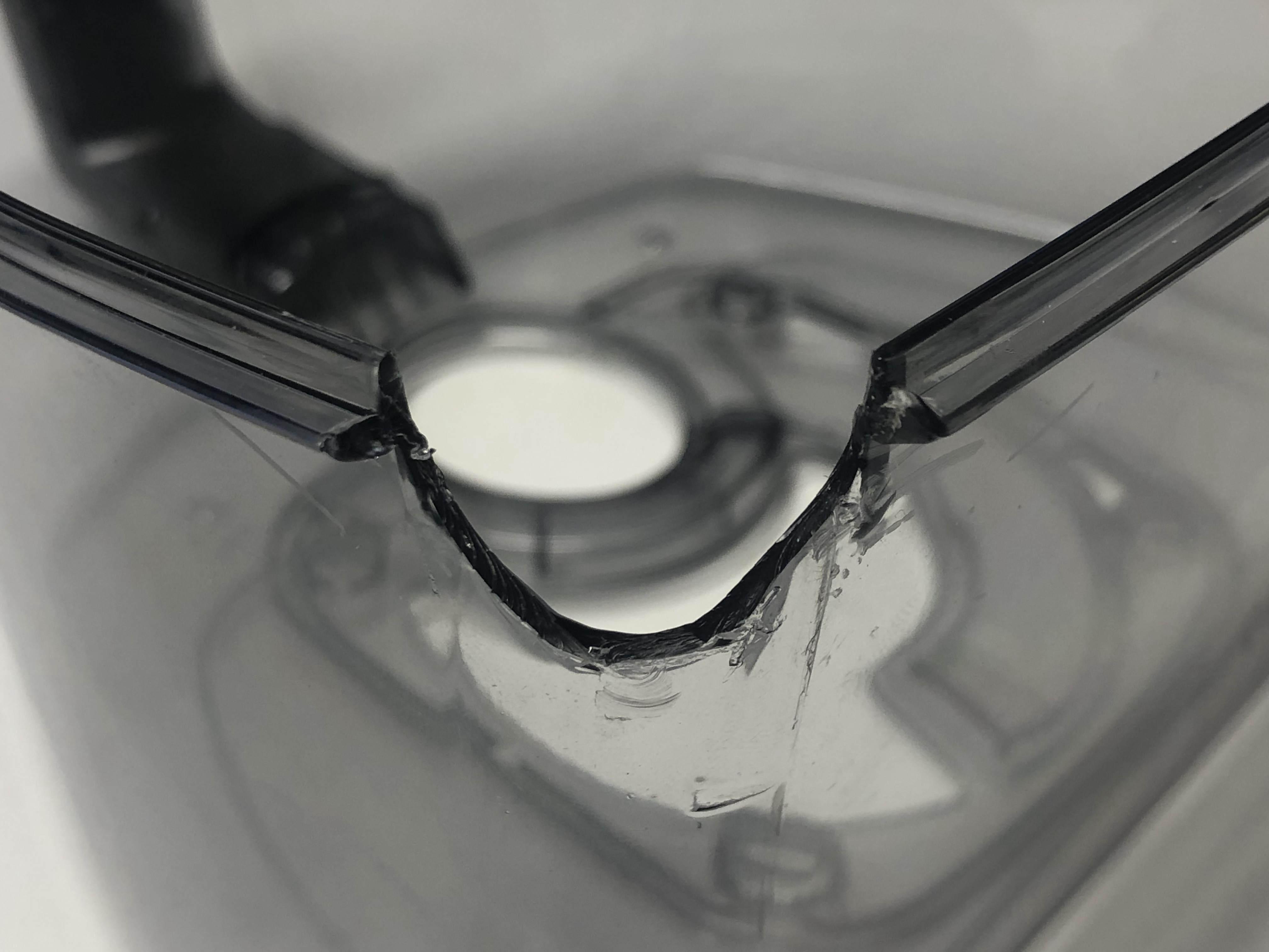
Apply Controlled Destruction
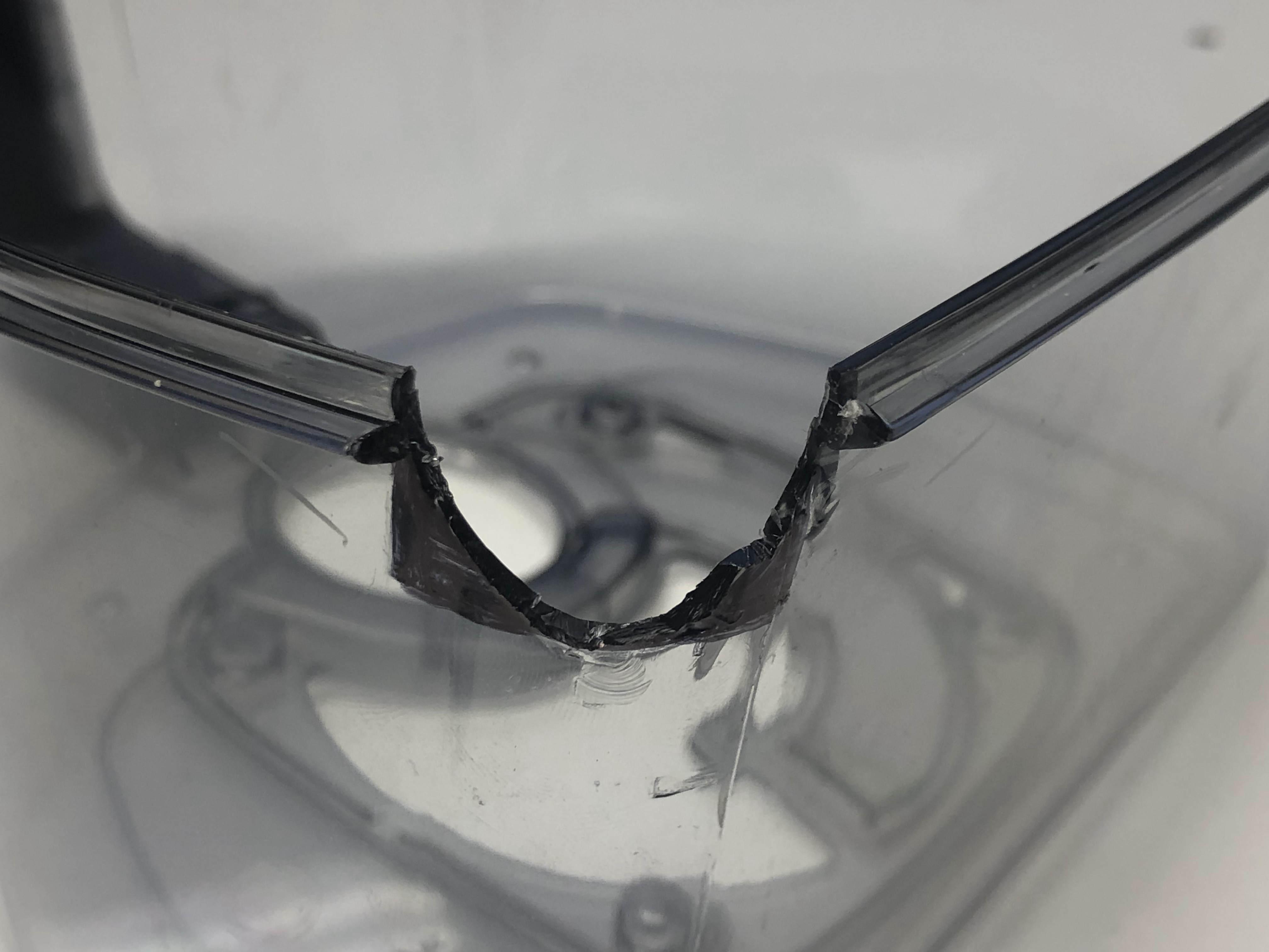
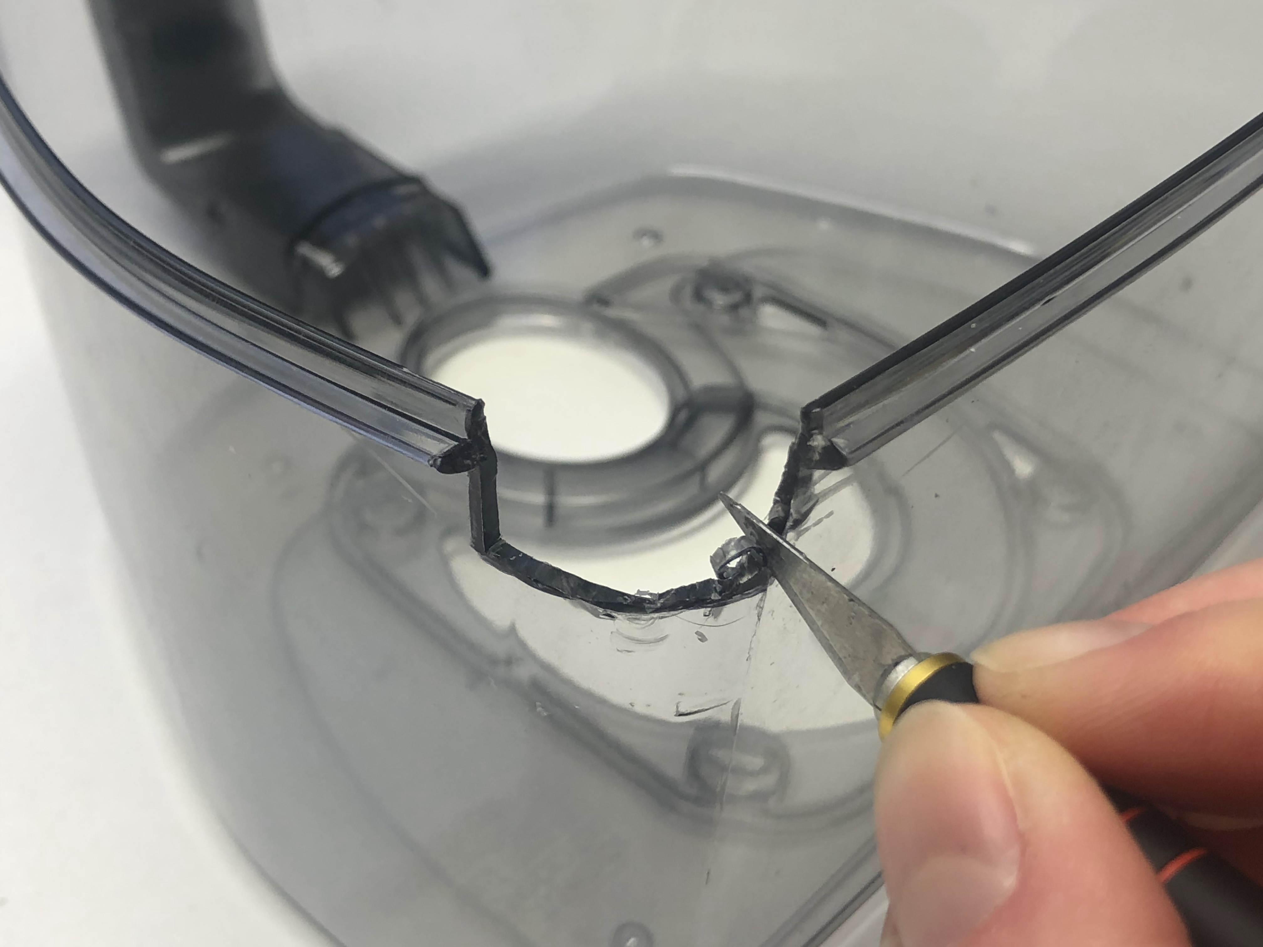
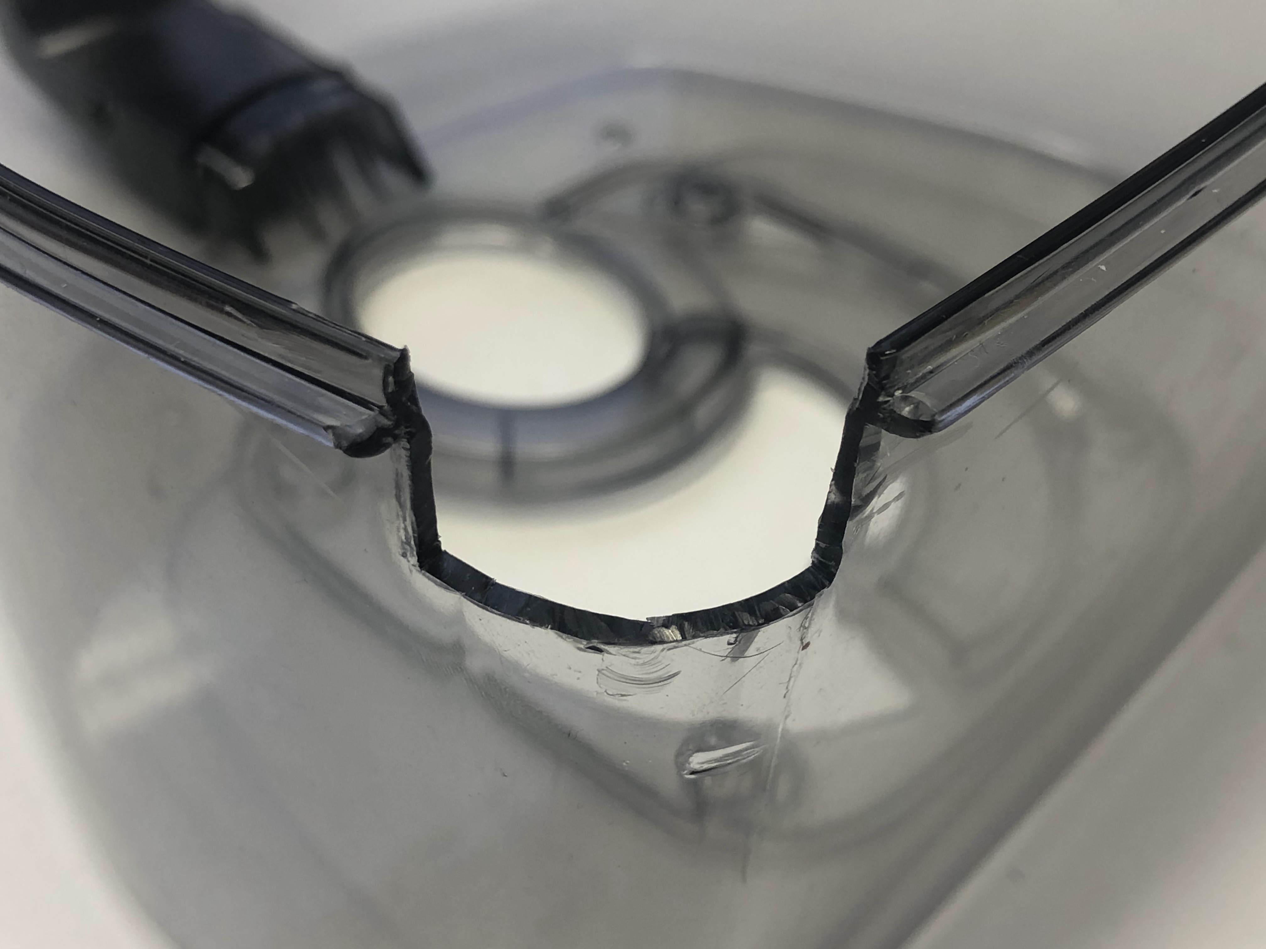
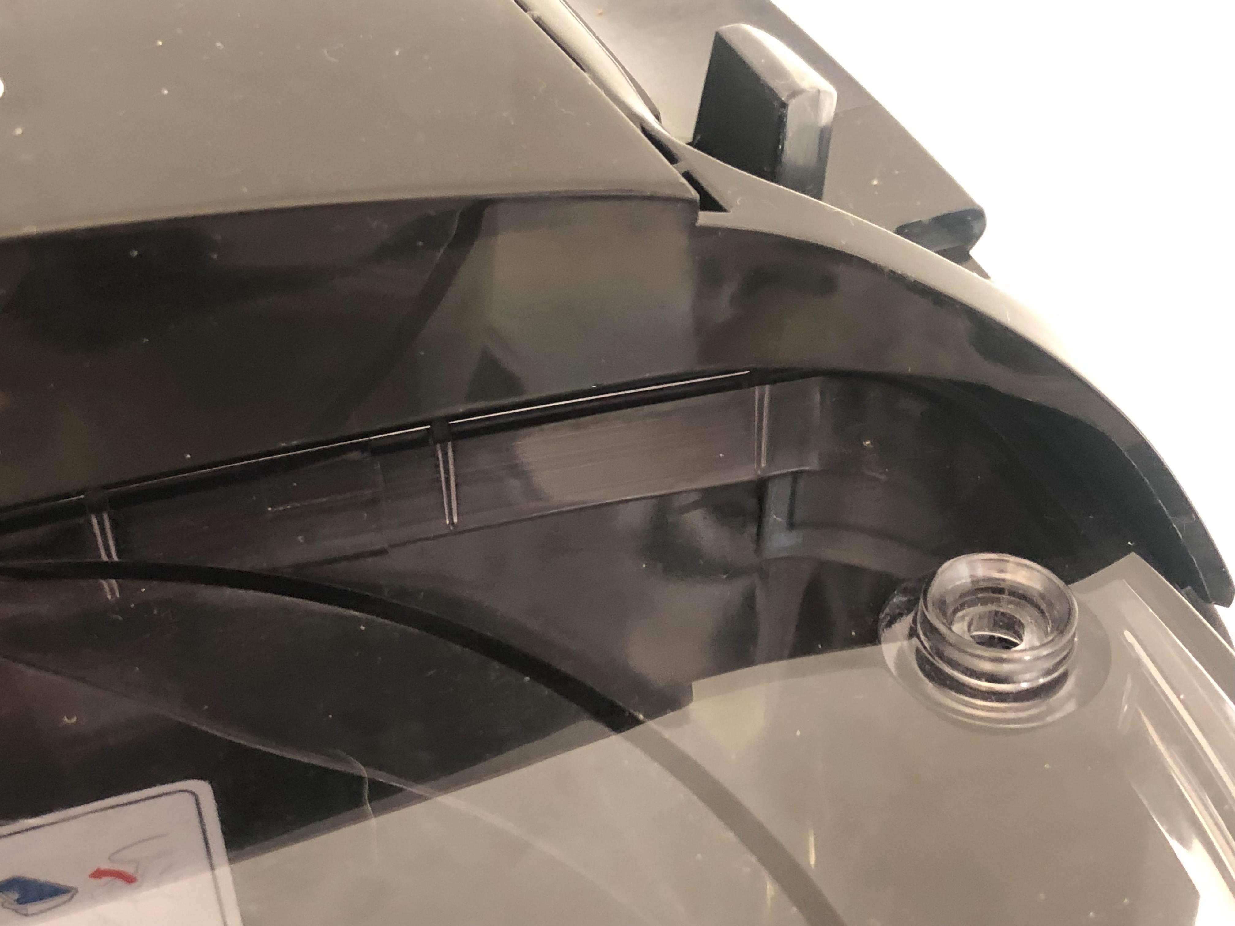
First is to simplify the shape of the gap. On this example the areas to cut out have been shaded in using a permanent pen. It is recommended to make this shape simple such as a quadrilateral, as this will make it easier to CAD a piece that can fit into the gap.
Then use a scalpel to cut this shaded material away, to leave a more easily measurable gap.
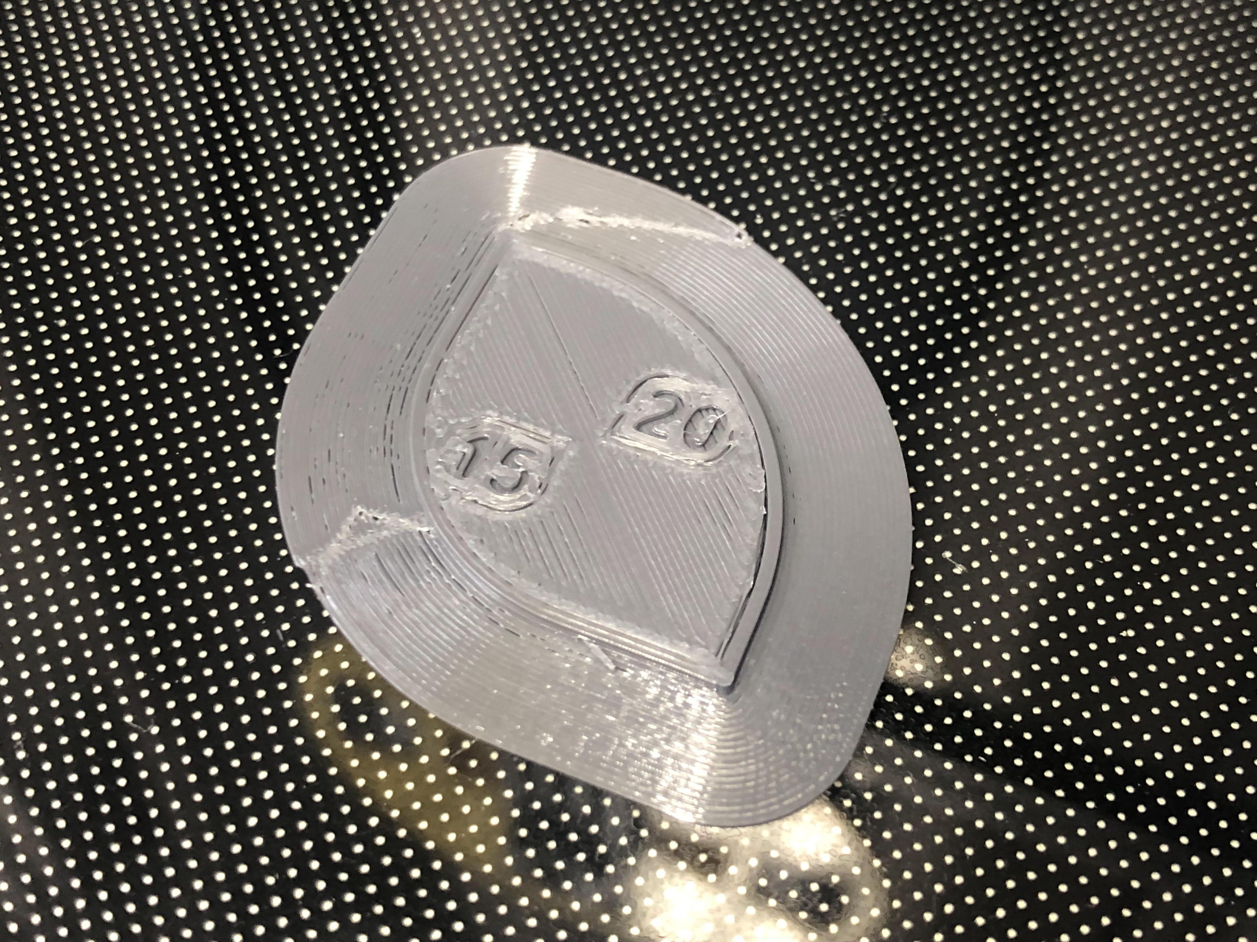
Model a Measuring Tool
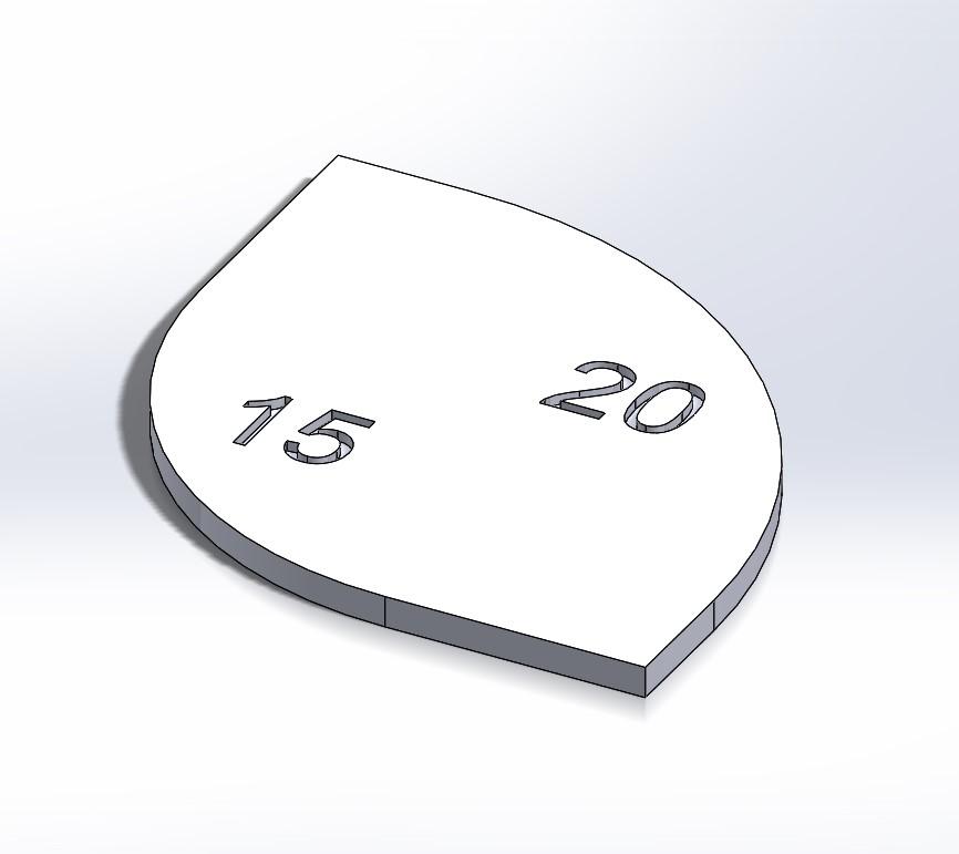
If you need to know what radius or angle to use, model a simple measuring tool to find these values.
If you do not have a tool to help you pre-measure, this simply comes down to guesswork and quick testing. So if your first measuring tool does not contain a perfect fit yet, no problem! Just take the information it gives you and adjust the measurements for a second measuring tool.
You can give multiple measurements to one tool, but make sure it is not too big, so that you can use it on the size of the product part that you are working with.
A few tips
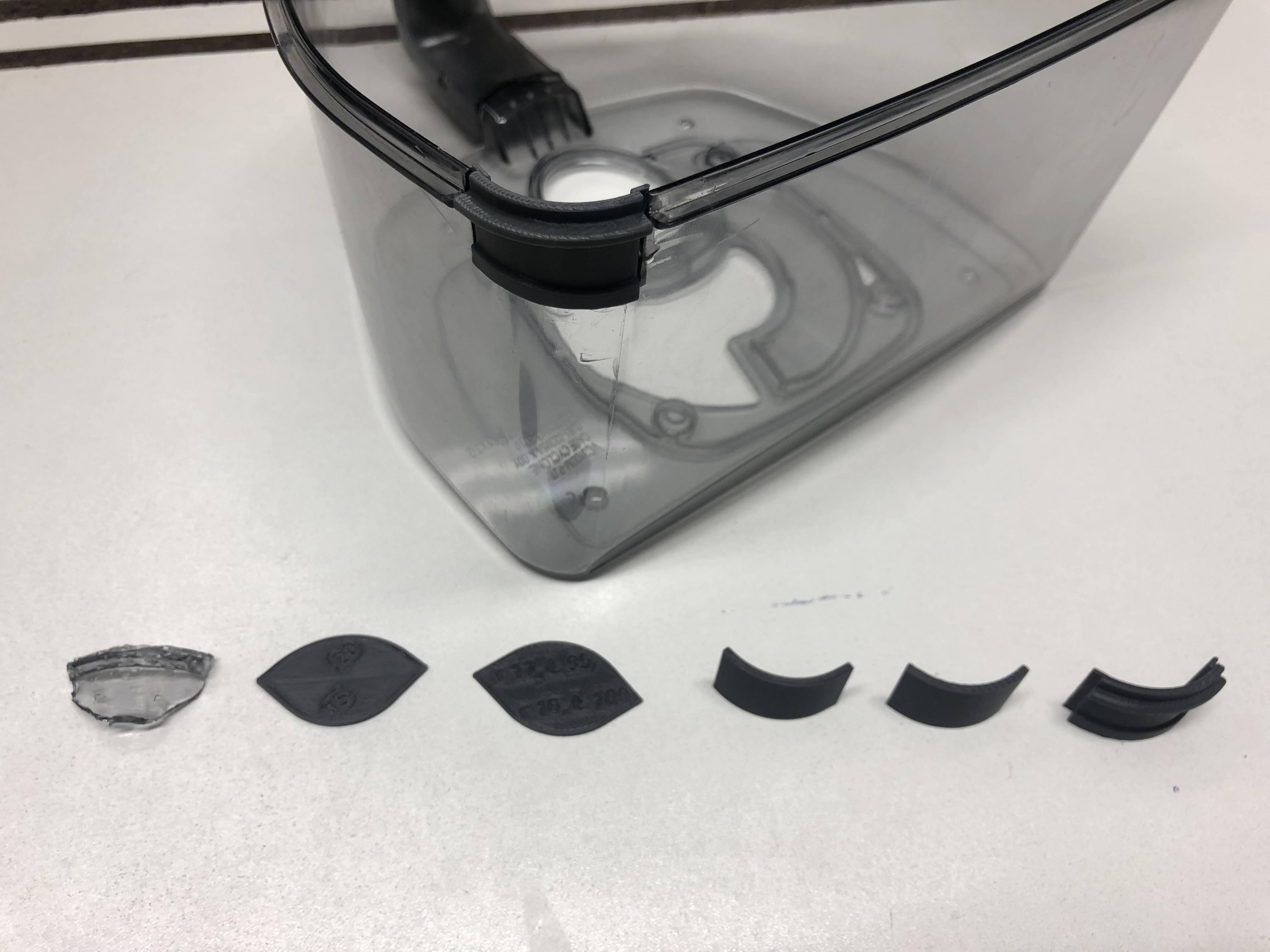
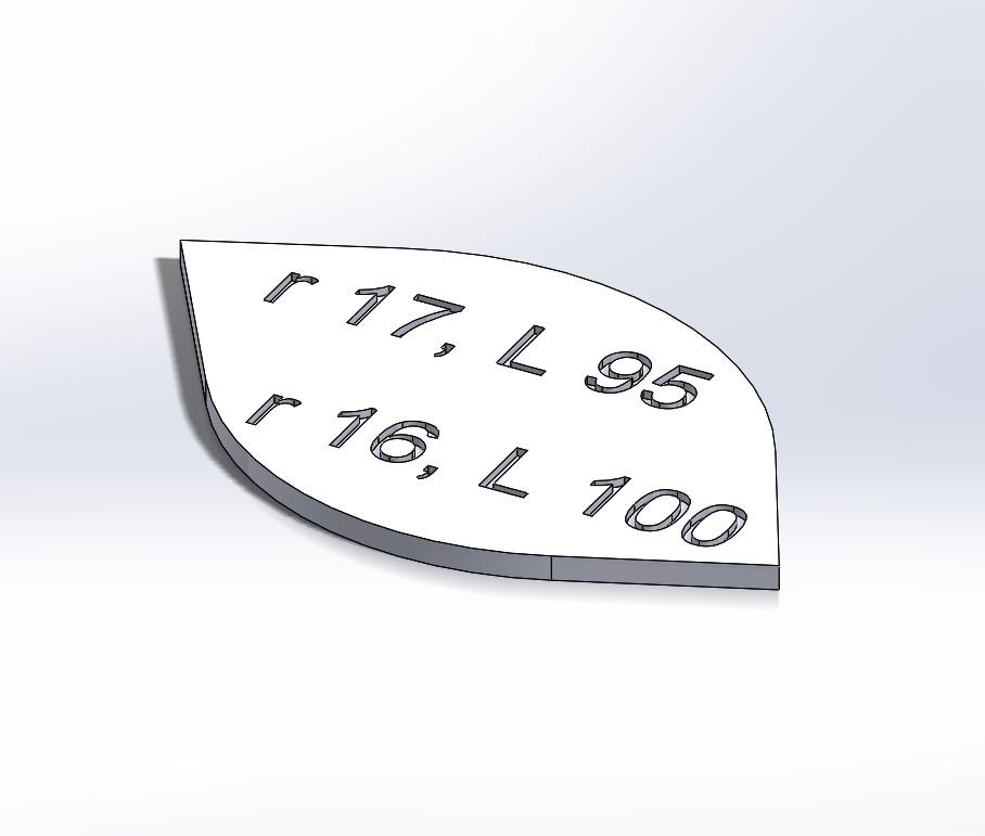
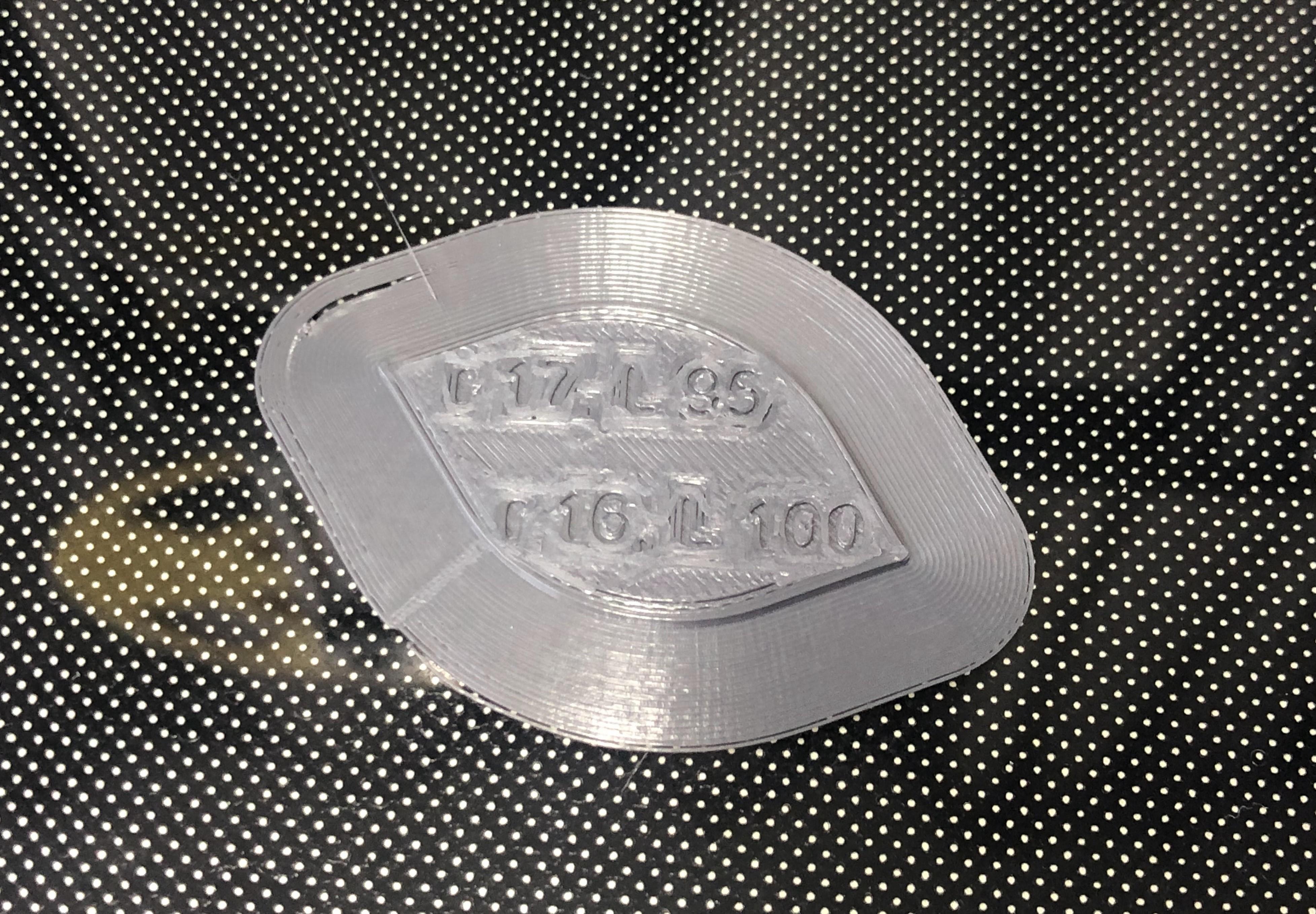
- Add extruded cuts with text/numbers to the tools to remind yourself of what values you used on each side of the measuring tool (as permanent pen can rub off). For example, in the first image above, the numbers represent the radii used on either side of the tool and in the second image, both radii (r) and angles (L) are noted.
- Make the tools flat and thin, to keep the print short and allow for a quick test. With thin tools, make sure to let the build-plate cool down a bit, otherwise your tool may warp when removing it off of the print bed.
- Ideally, think about which settings you are going to use to print the tool. If you are using a layer height of 0.2mm, for example, make sure to give the tool a thickness that is a multiple of this layer height, so for example: 0.6, 0.8, 1.0, or 1.2.
There were two iterations done for the measurement tools in this case study, see the images above.
This tool was used to measure the radius of the corner and the angle between the sides/walls of the dustbin.
Slice the Measuring Tool
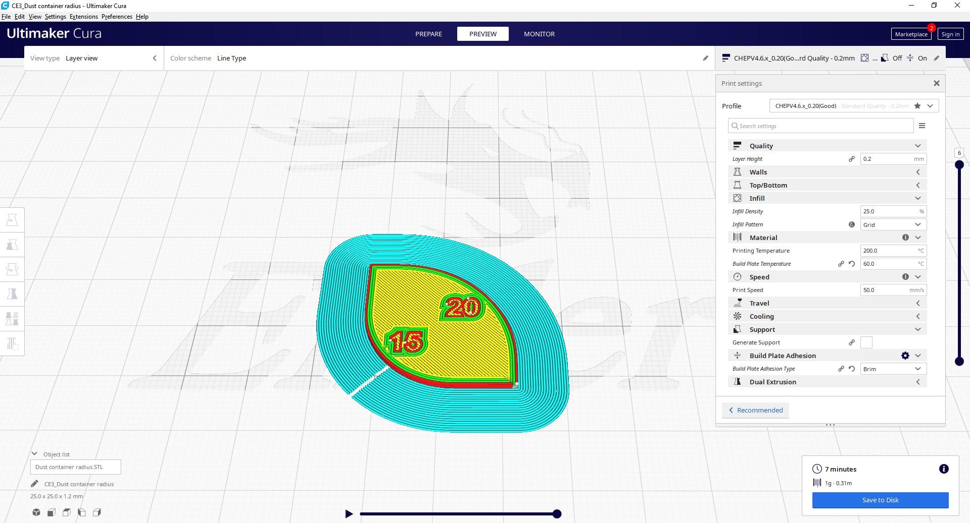
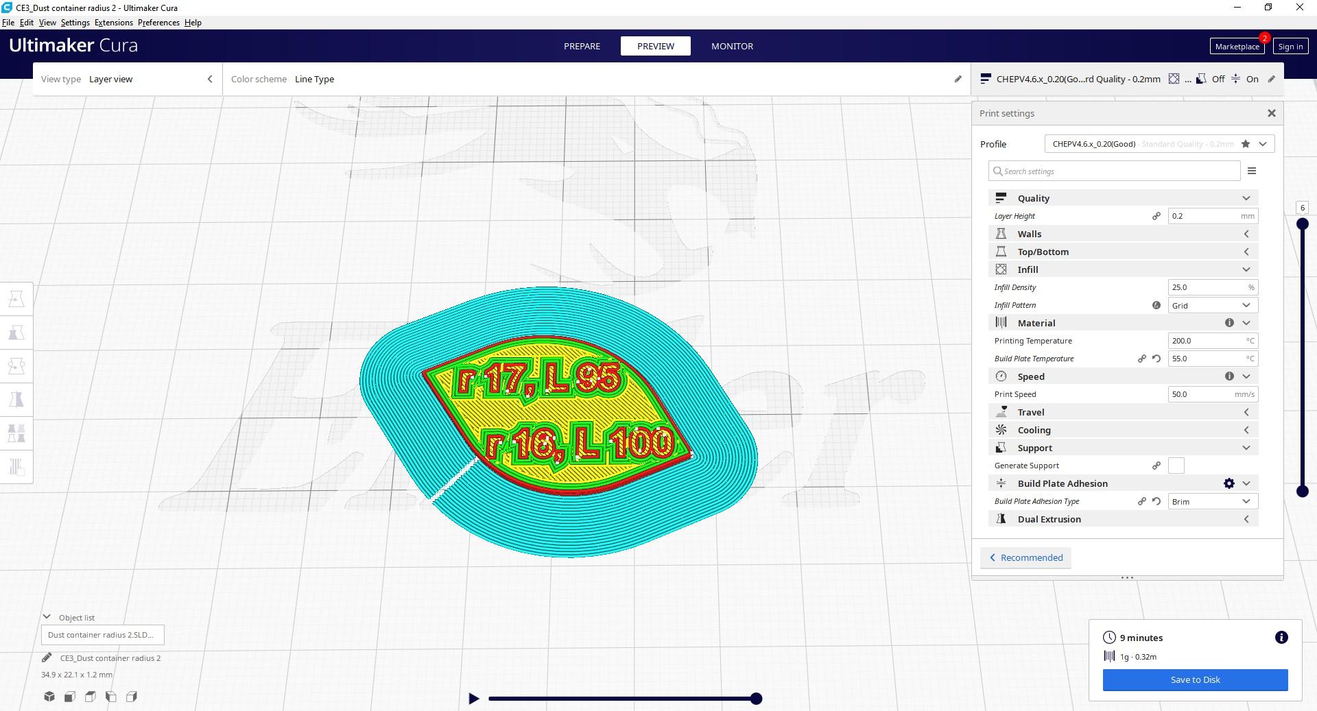
Slice the measurement tool with basic PLA settings (unless you are using a different material for this repair), but make sure they are detailed enough for the lettering to be readable. A layer height of 0.2mm is recommended, with a brim for better bed adhesion.
The images above show the two iterations of measurement tools sliced in Cura.
Print the Measuring Tool + Post Processing
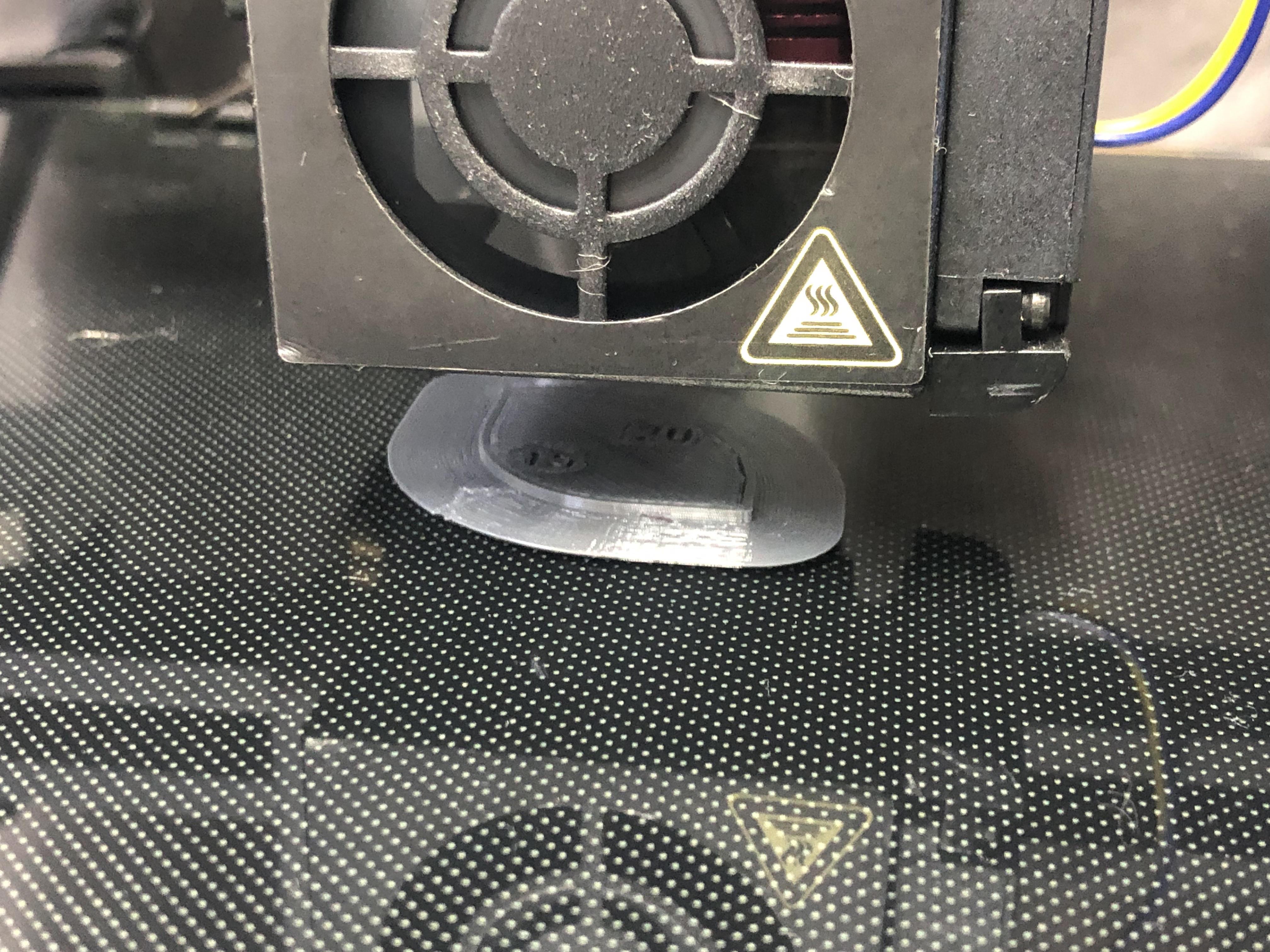
You can use the time the printer takes to print the brim to adjust the bed level if needed.
Post processing
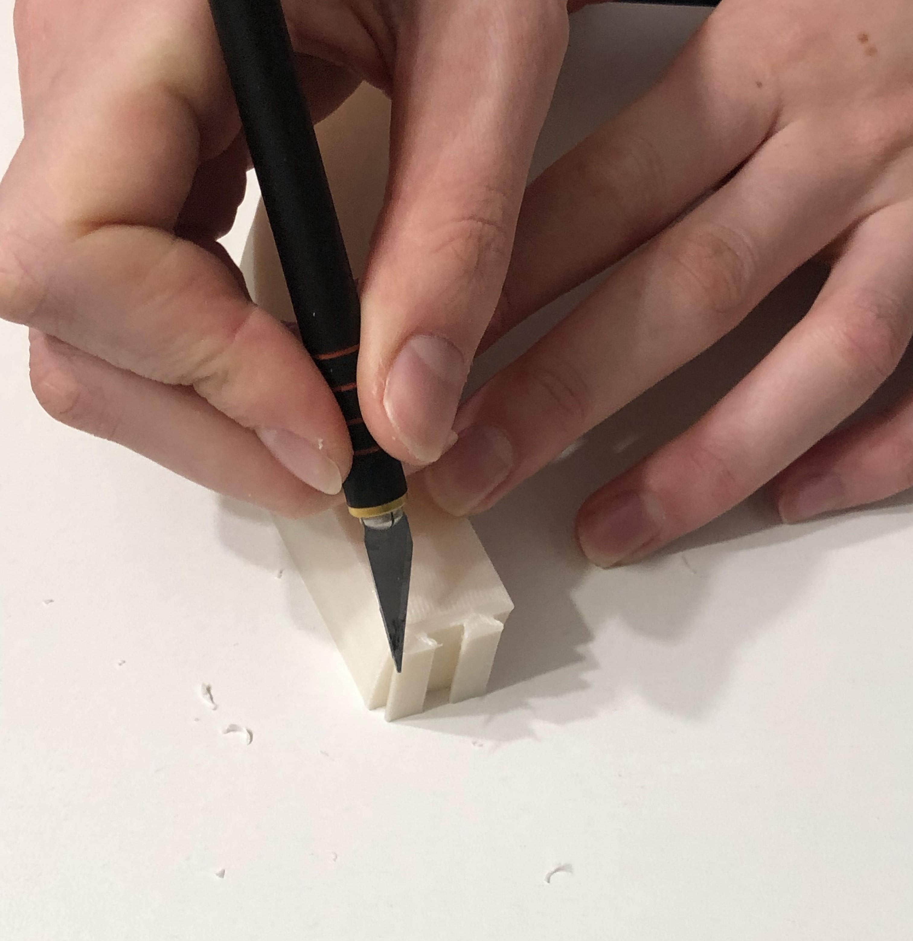
The post processing includes trimming away the brim around the edges of the measuring tool. This should be doable by hand, but if you want to be really accurate and precise, you can use your precision knife. Run the knife around the part edges to remove the brim right at the start of the part, but be careful not to cut into the part itself!
Please note that the last picture above shows post-processing on a model that is not related to this instructable!
Measure the Gap With a Calliper
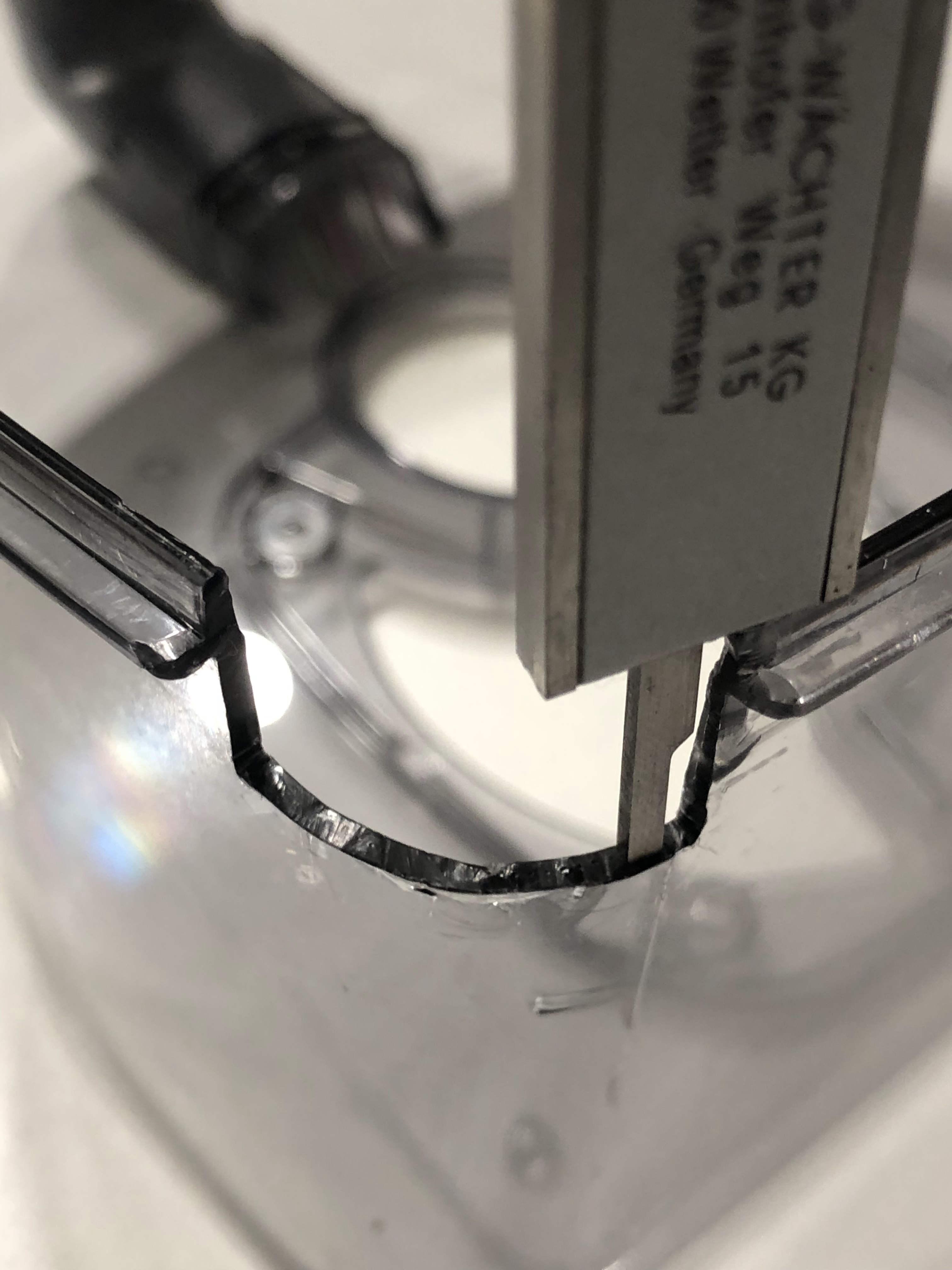
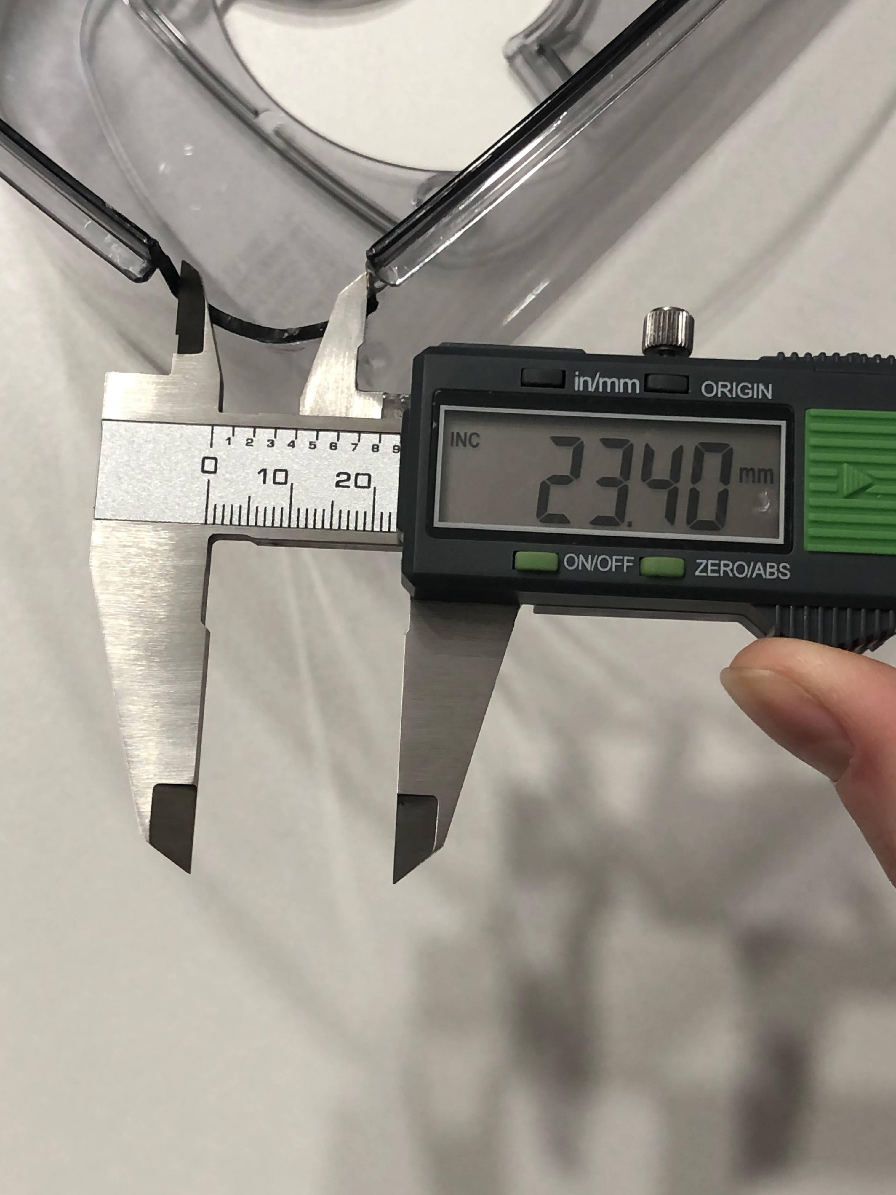
Take the remaining measurements that you need to model an insert that fills the gap or reinforces the fracture, using a calliper.
Using a calliper in contrast to a regular ruler will minimize the amount of iterations you need to find the perfect fit due to the accuracy!
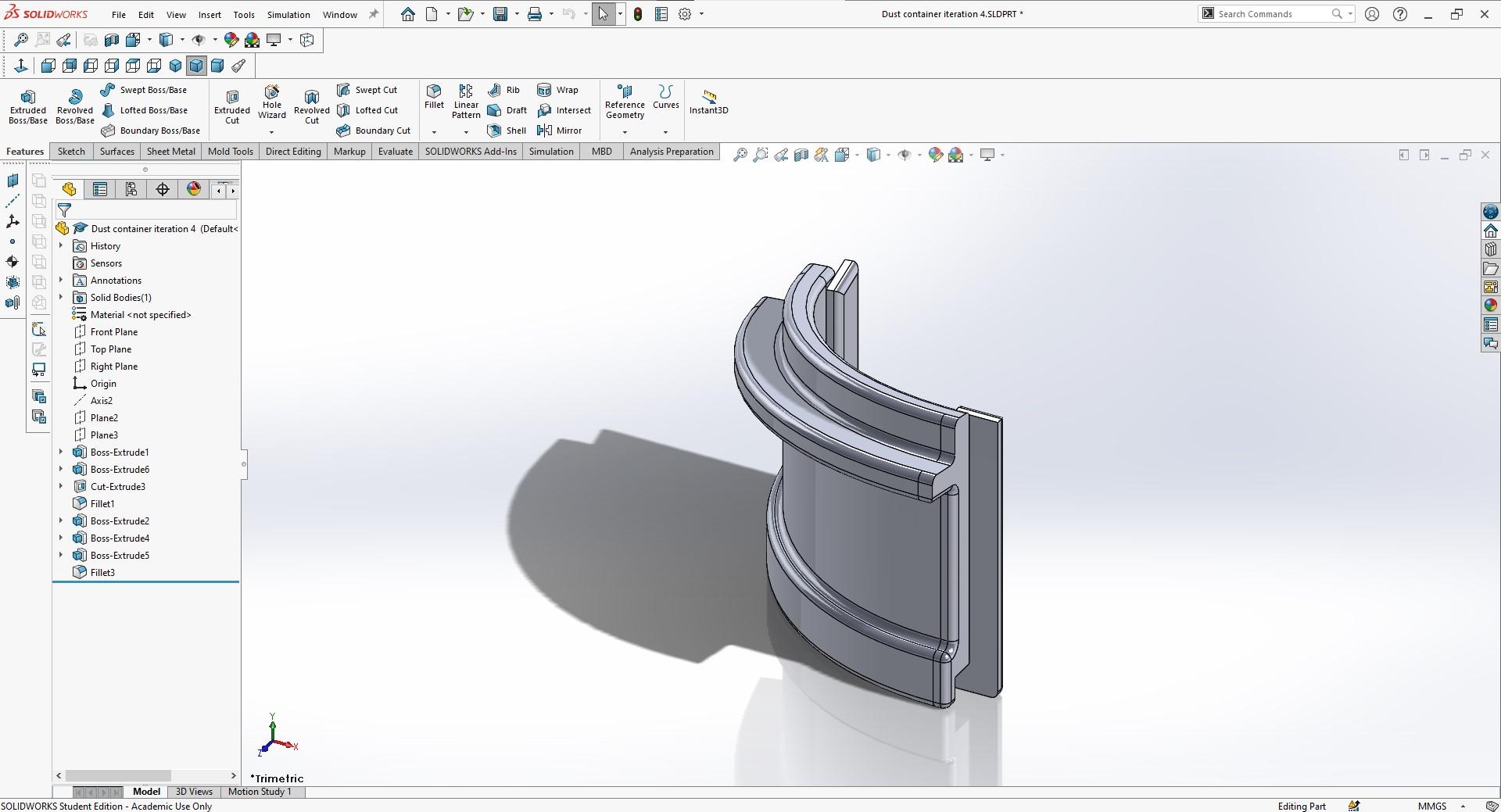
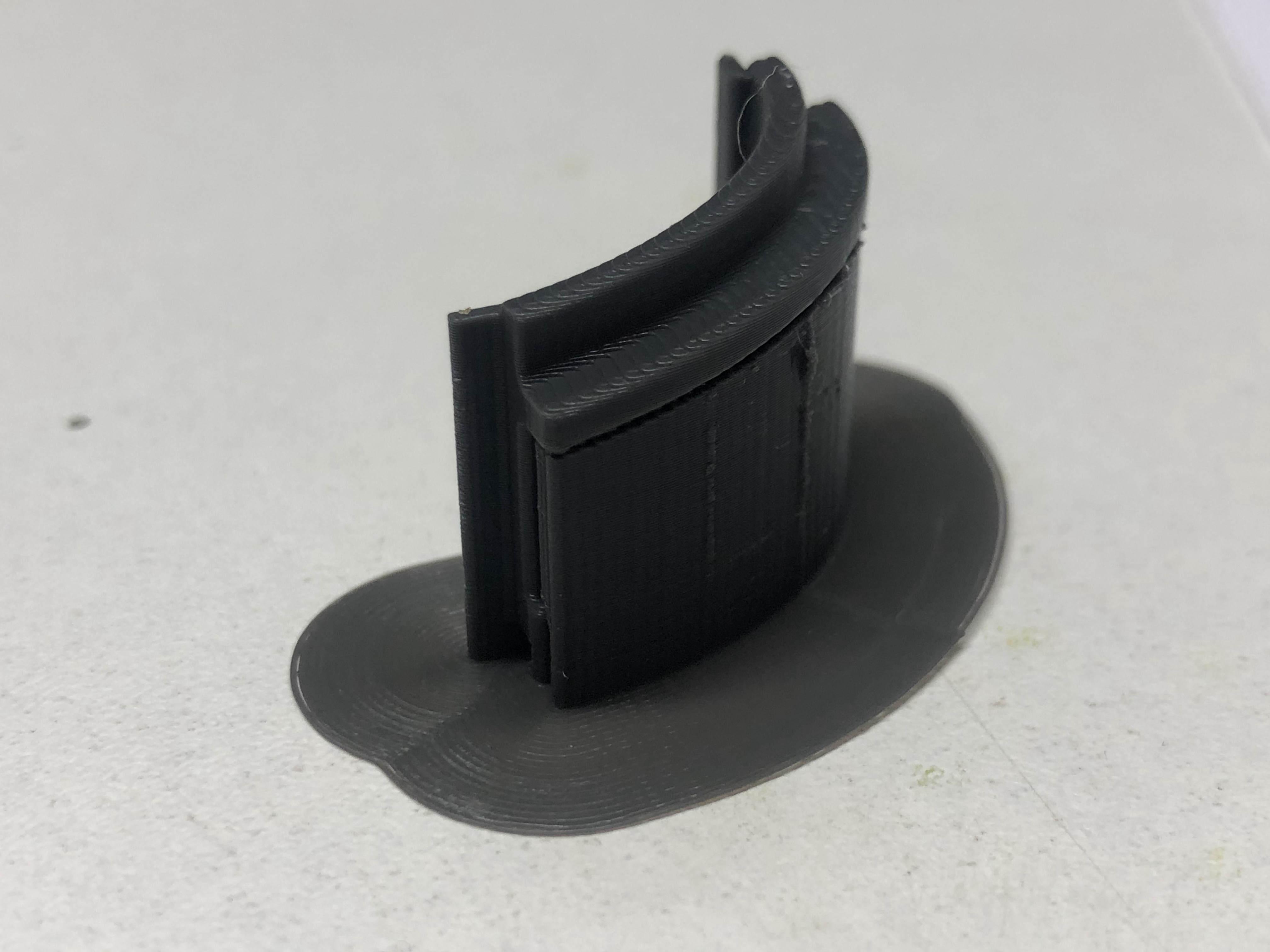
Model an Insert
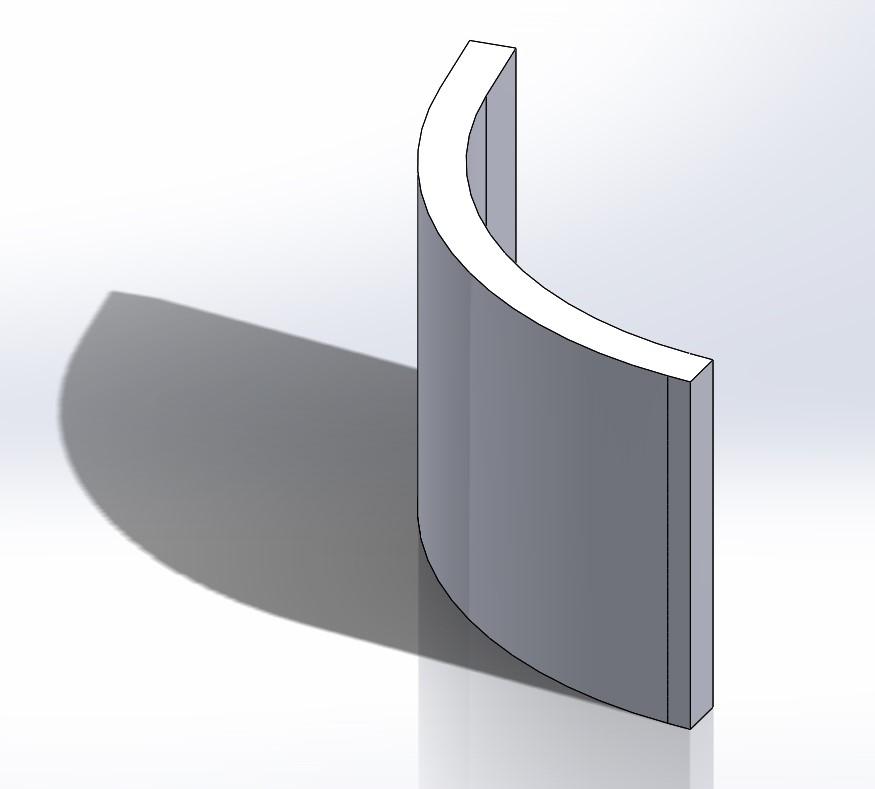
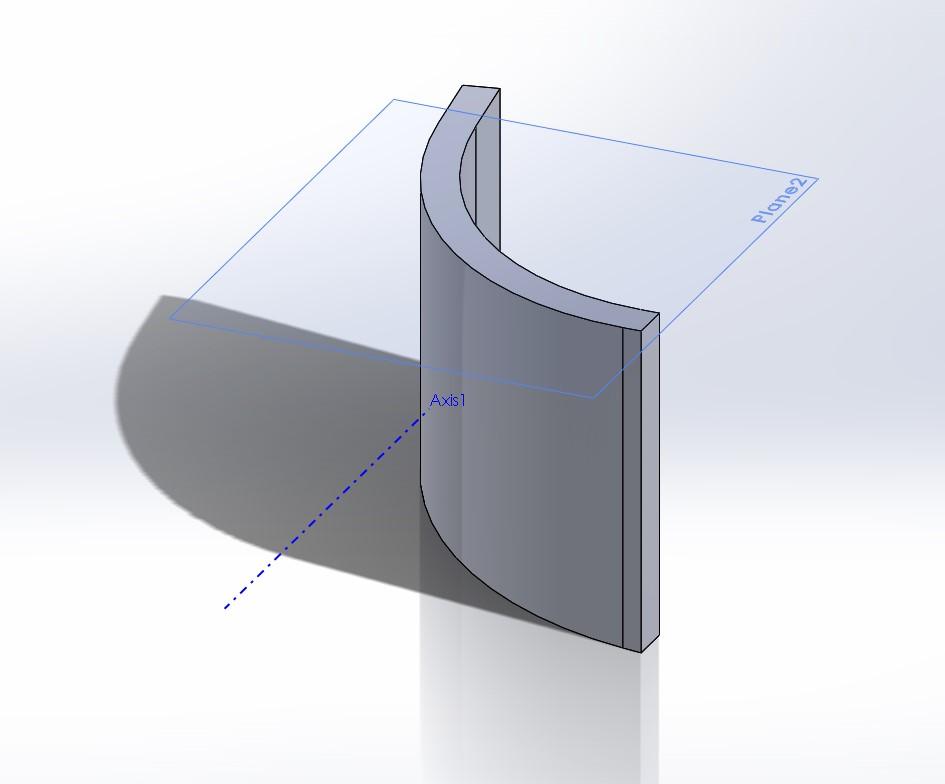
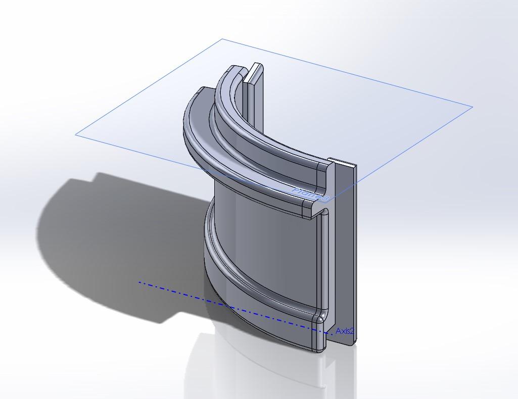
Once you have collected all the measurements, you can start creating a model. The trick in doing fast iterations on the model is to keep it as simple as possible, for as long as possible. As you can see in the images from the case study above, only the last iteration includes all the details for the insert.
This is because they were only added to the model after the general fit and geometry of the insert was correct. By iterating in this way, you can make sure that the printing and modelling time are minimal for each iteration. Therefore making the entire process a lot faster than if you add detail to them from the start.
There were three iterations done for the insert in this case study, see the images above.
Slice the Insert
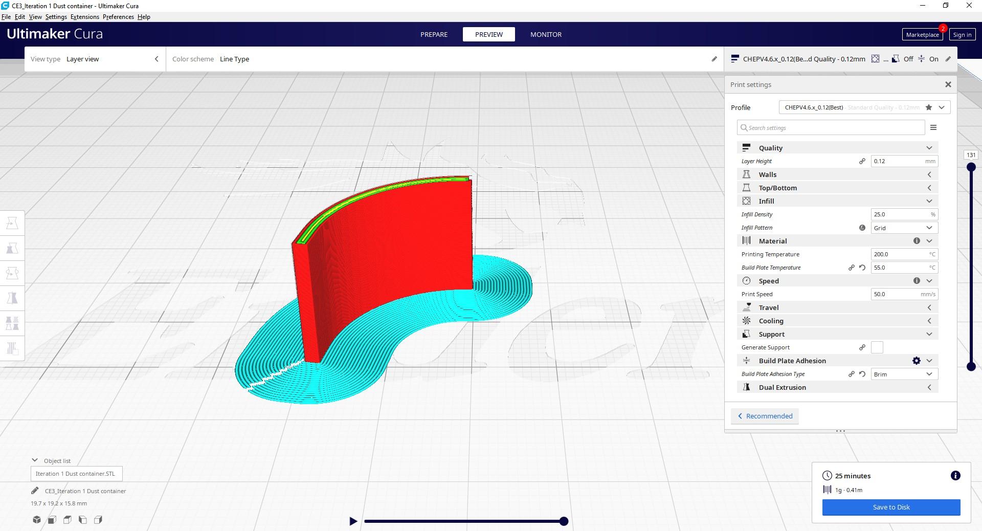
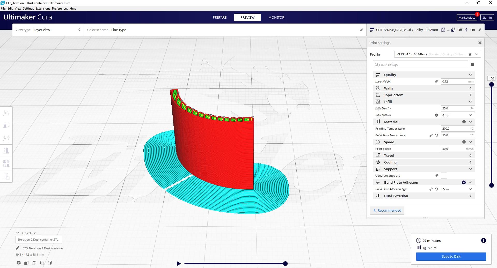

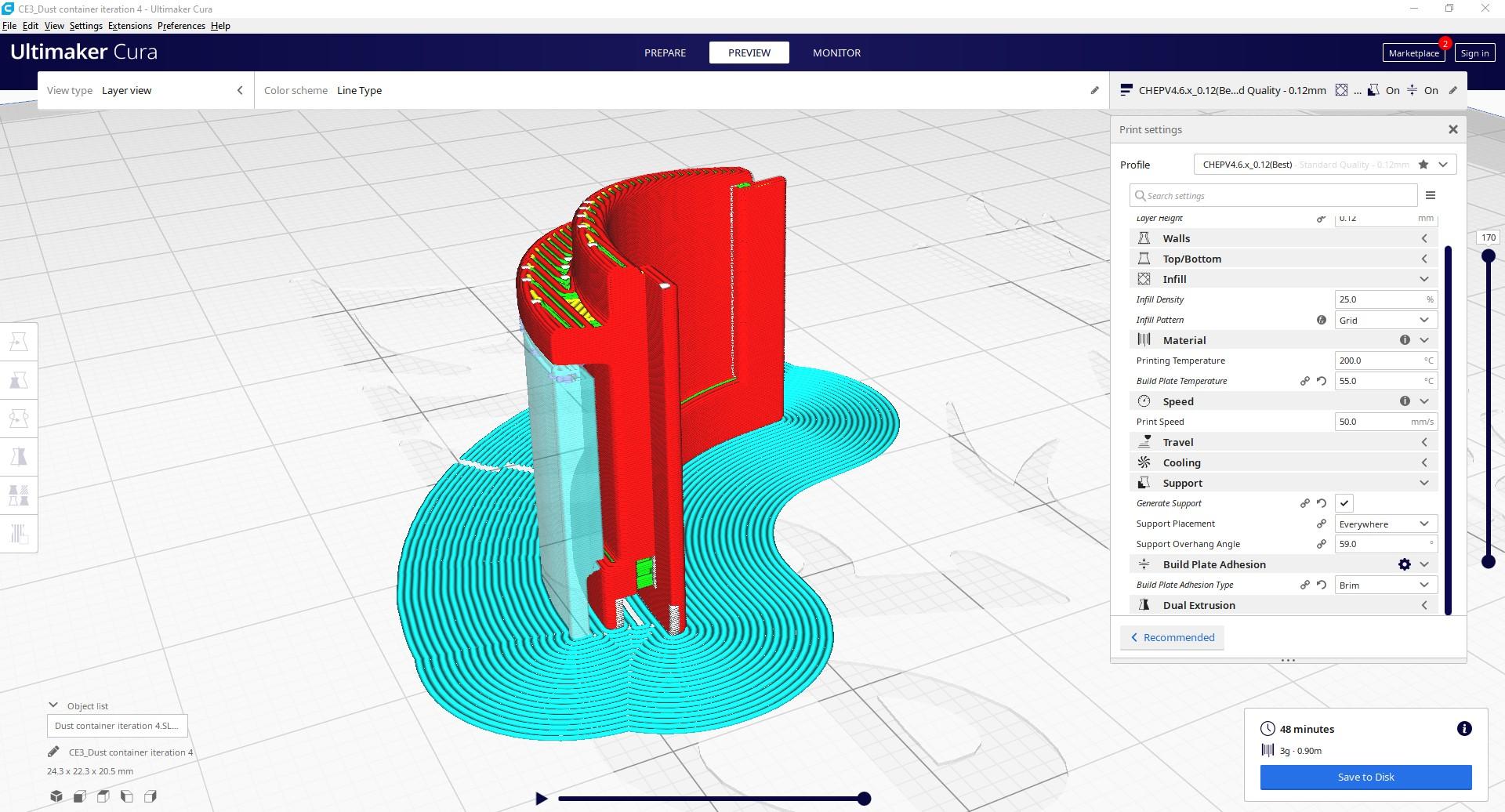
For the insert, it is recommended to change the slicer settings to a more precise profile, for example with a layer height of 0.12mm. This is especially important for smaller inserts and/or inserts with lots of detail.
Keep in mind that you may want to use the same exact settings for each iteration of the insert, even if the geometry does not yet need it in the first iteration. This is because changing the settings throughout iterations too much can interfere with the tolerances of the insert.
If your model needs to be printed with support, always check if the support is generated properly and what angle is going to be the best print angle.
The images above show the three iterations of inserts sliced in Cura.
Print the Insert + Post Processing
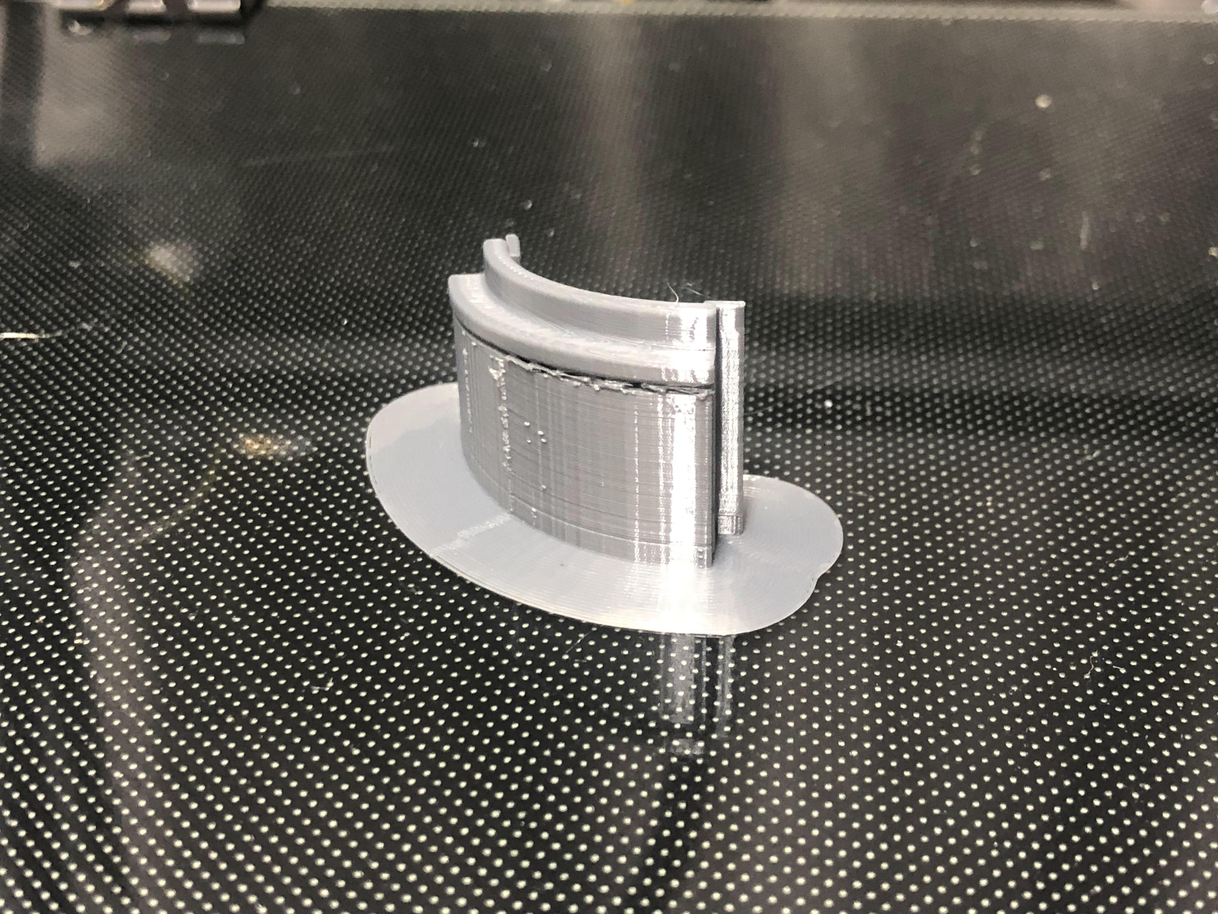
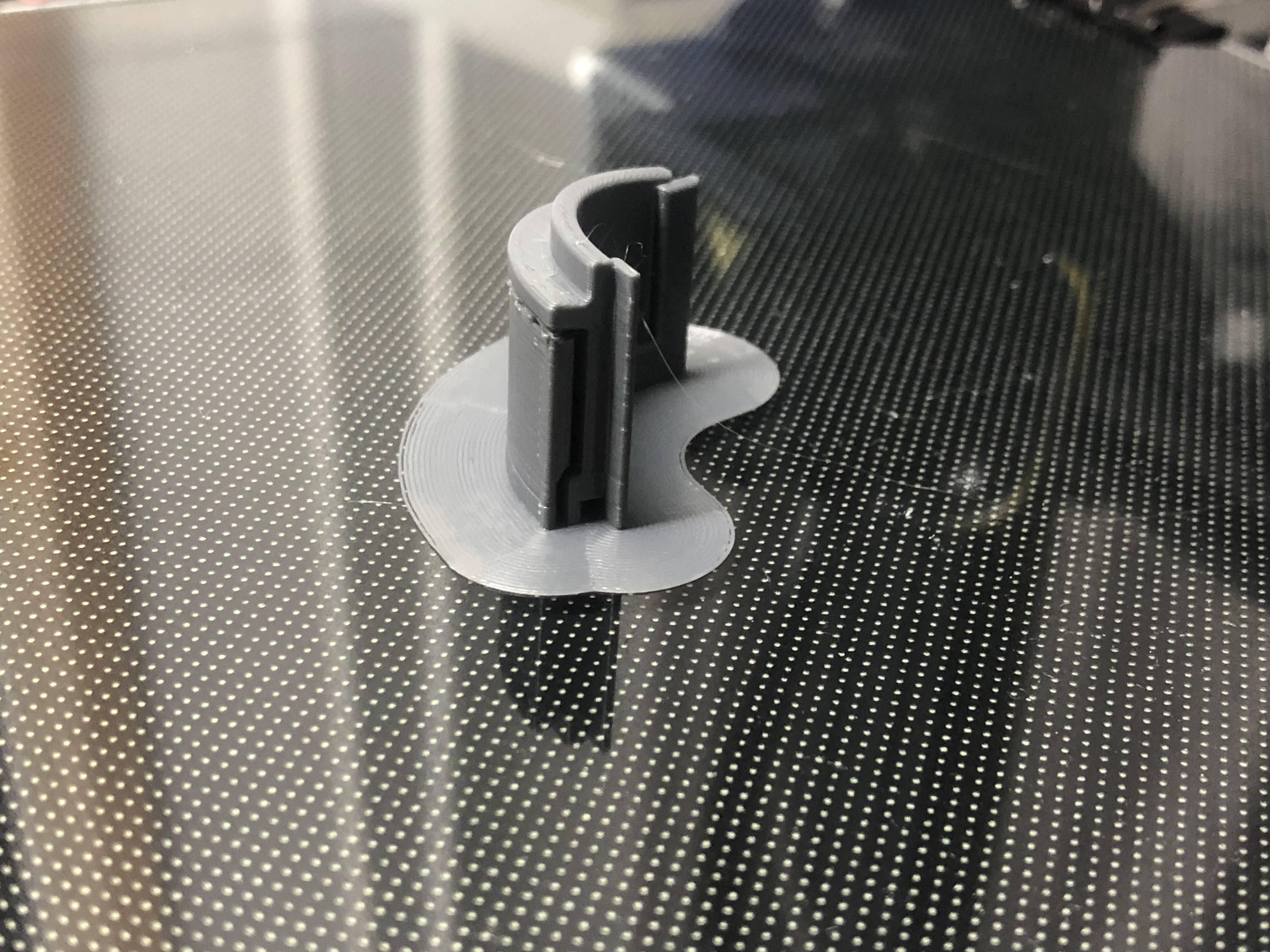
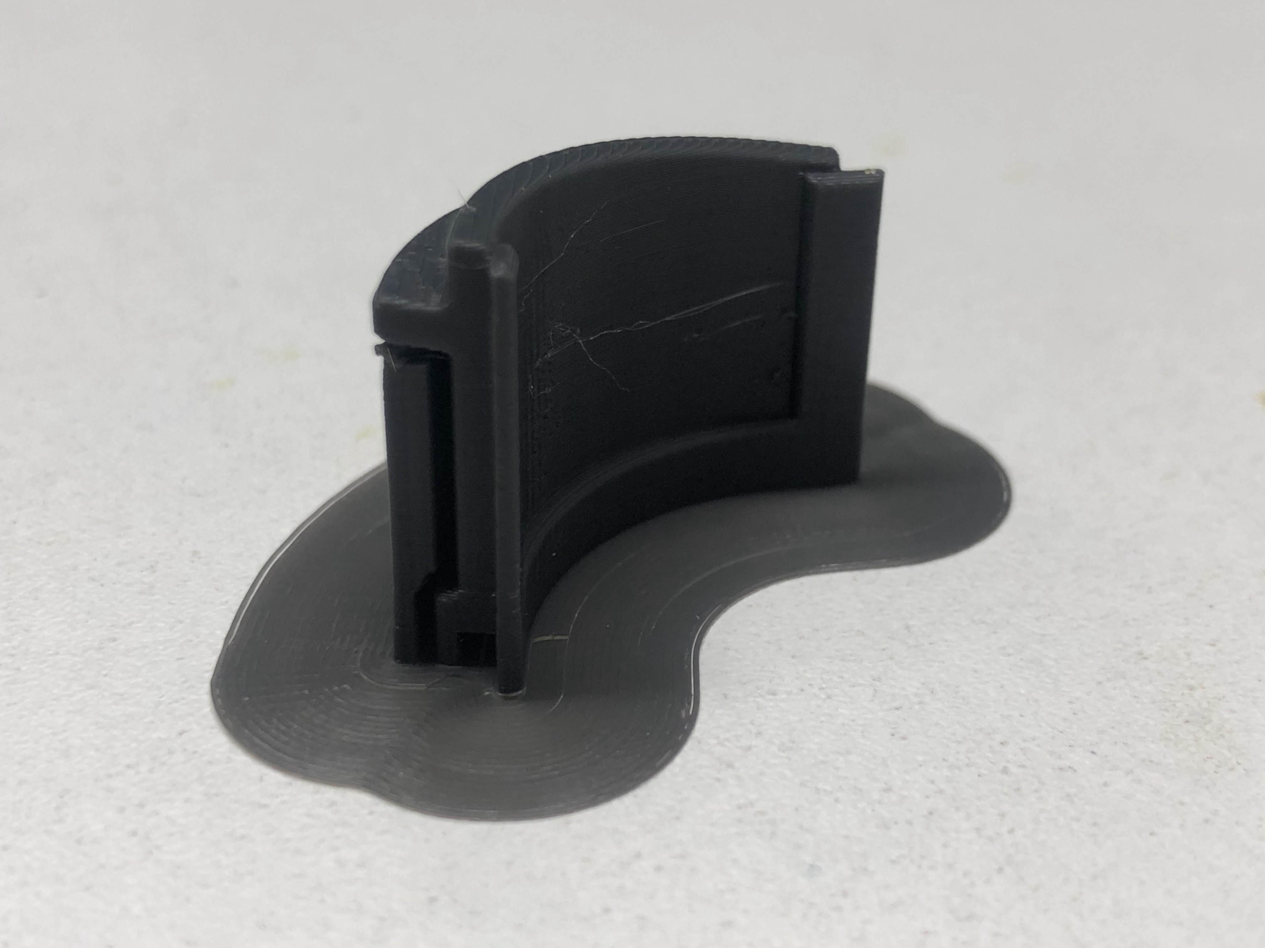
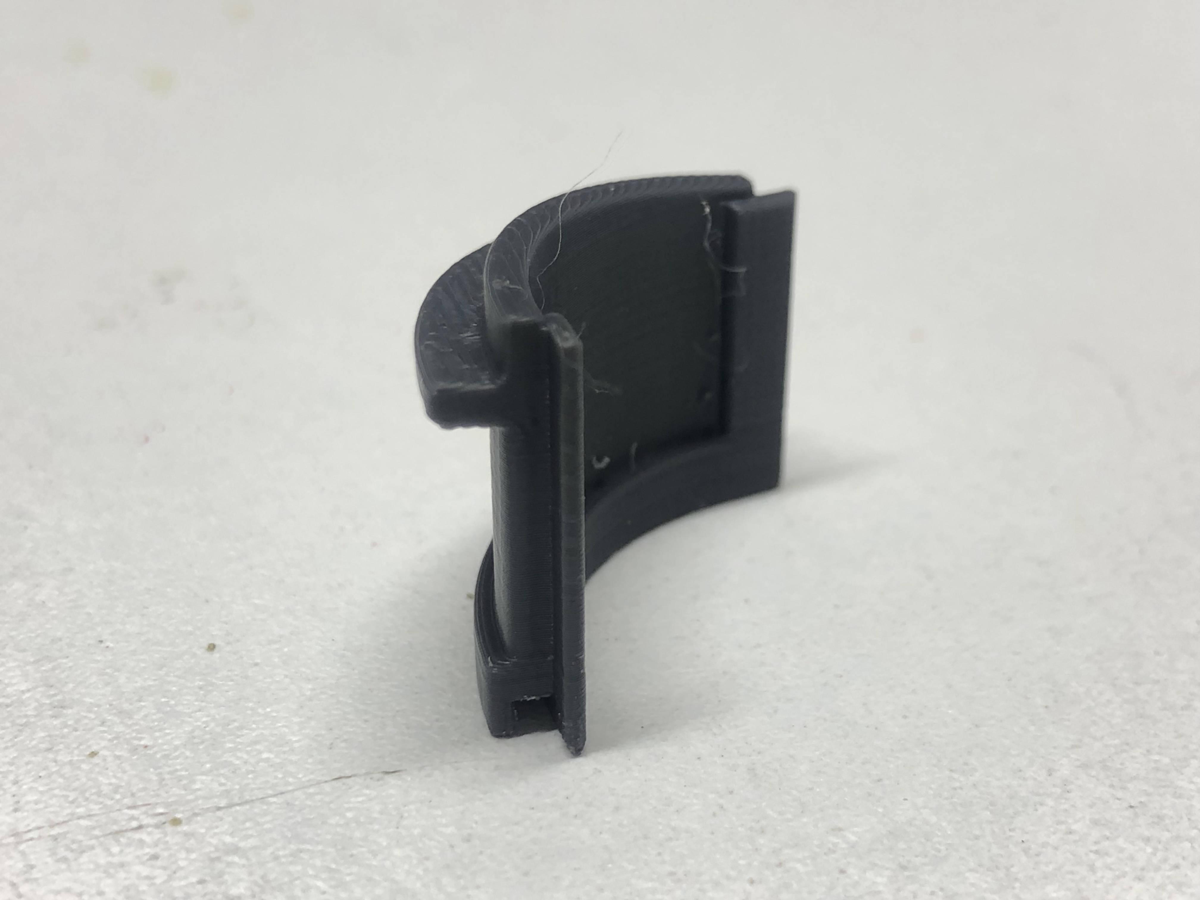
The same explanation that was used in step 4 applies to this step, but of course remove any supports from your print before moving to the next step!
Testing the Insert
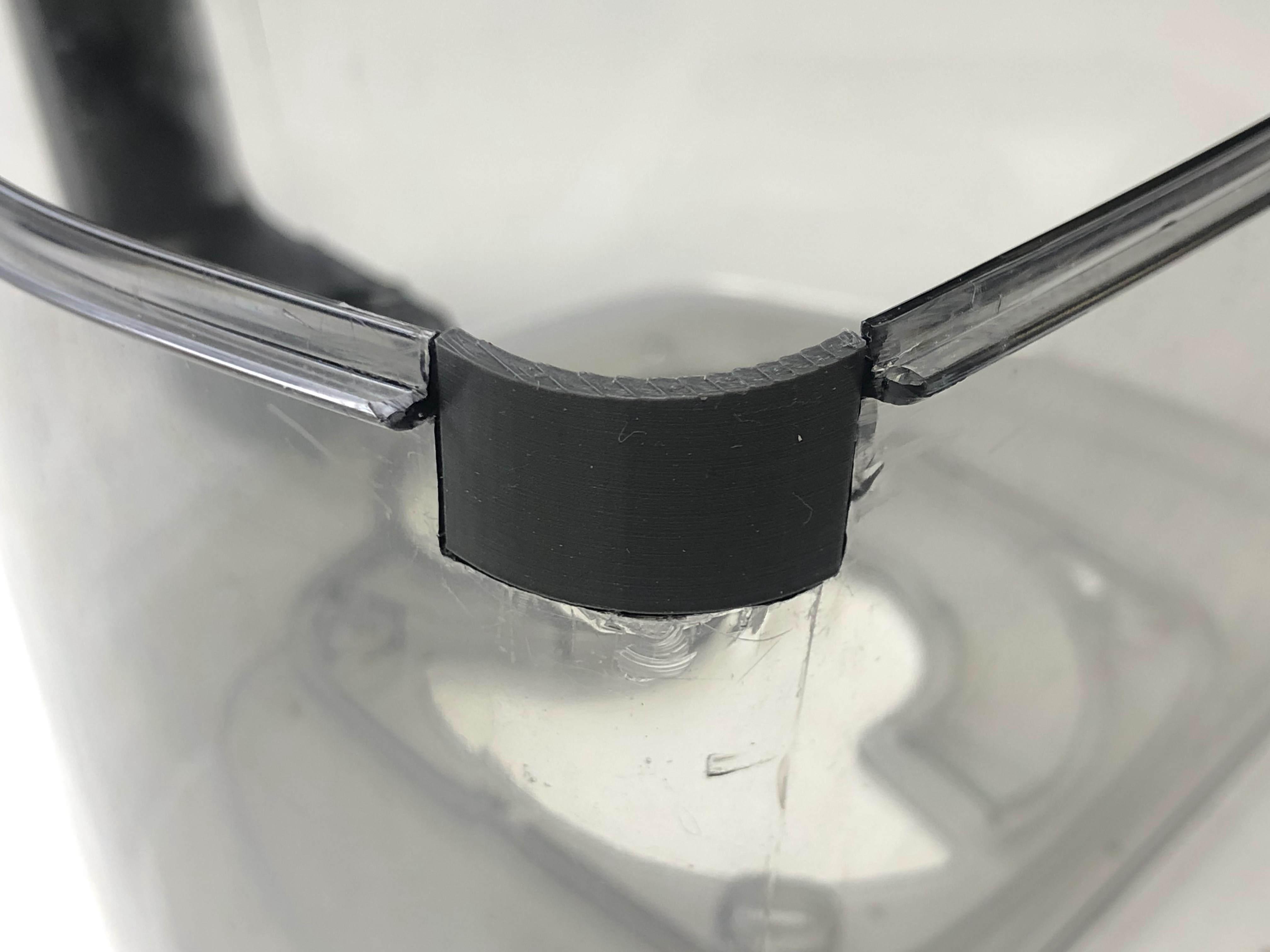
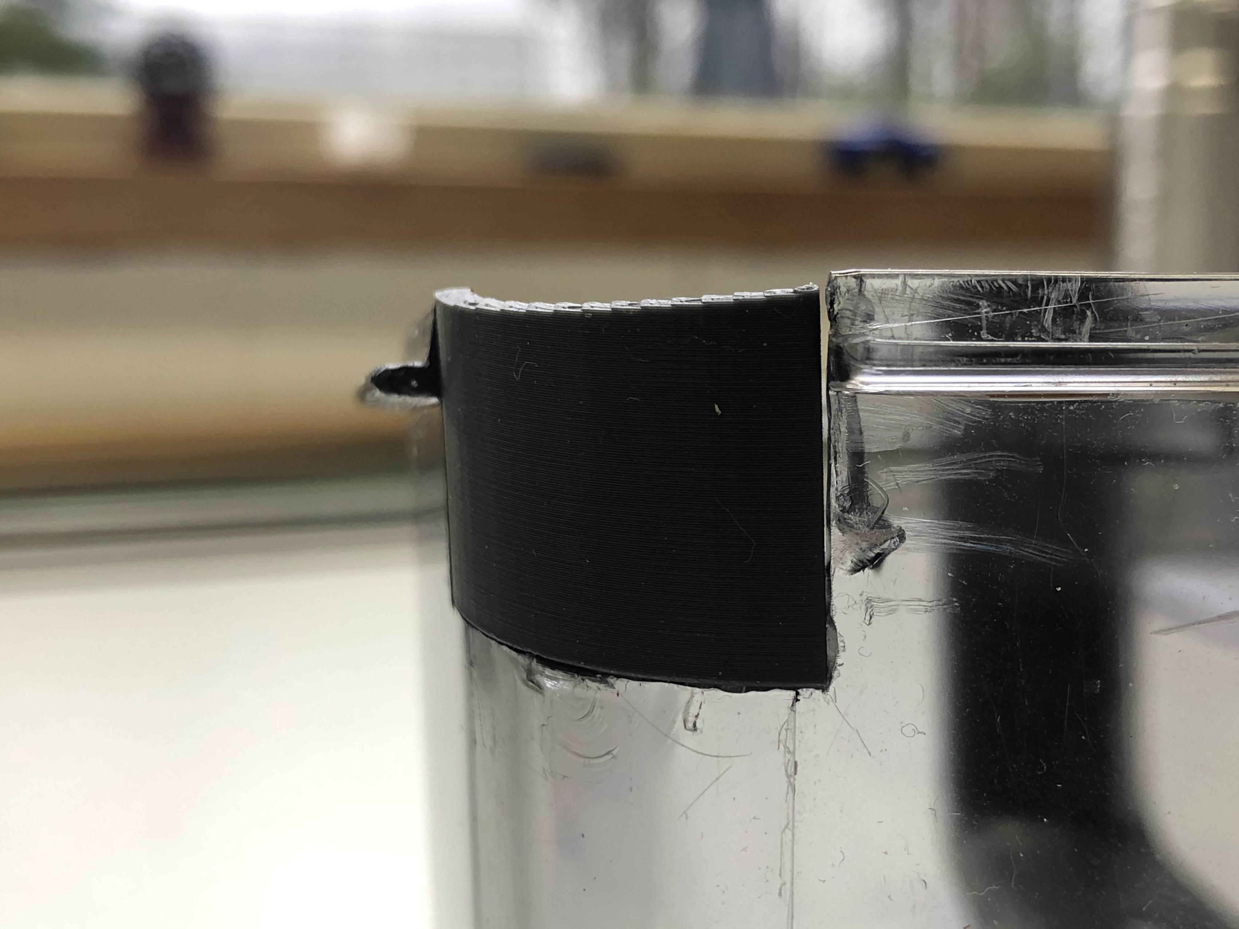
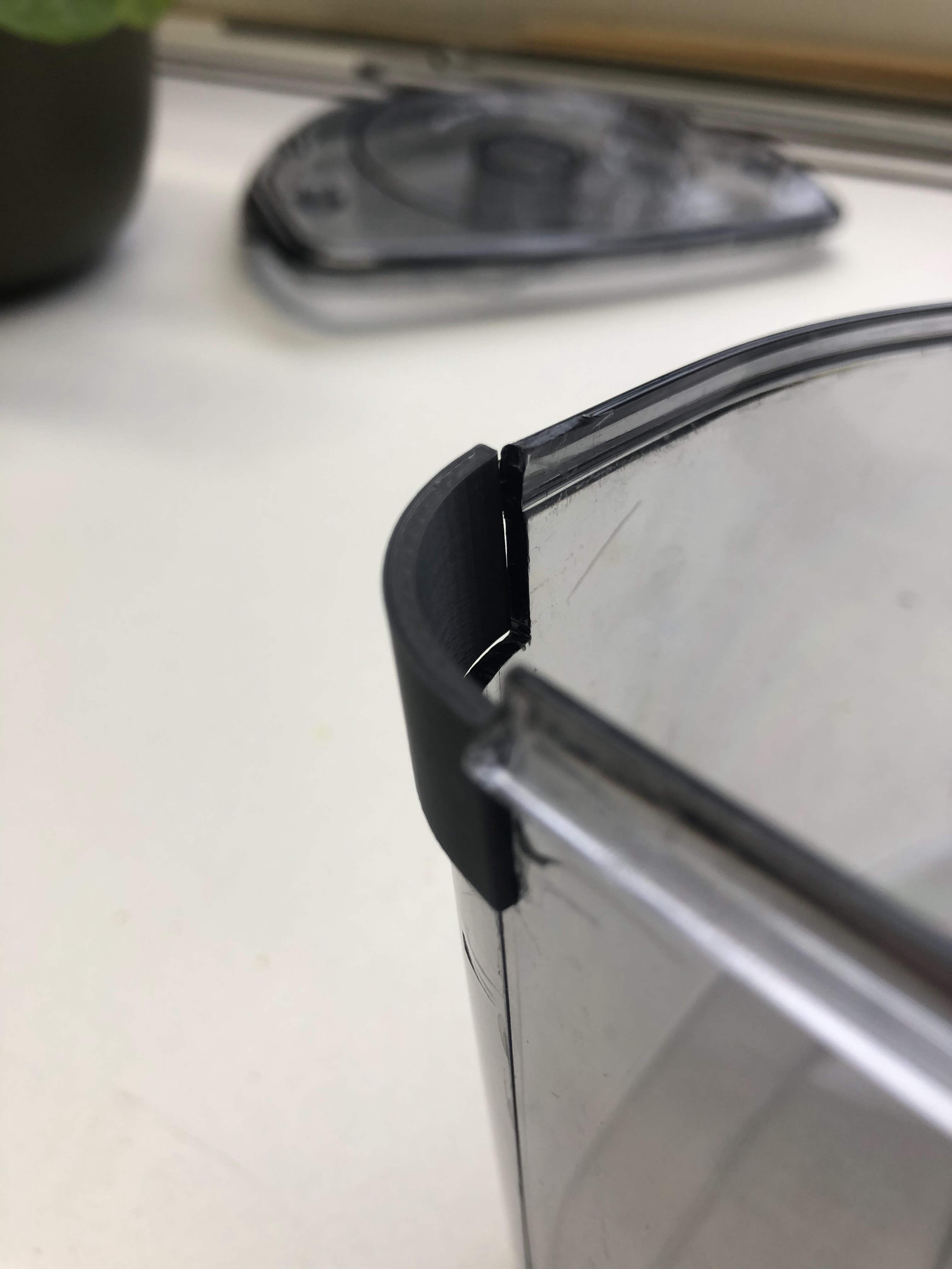
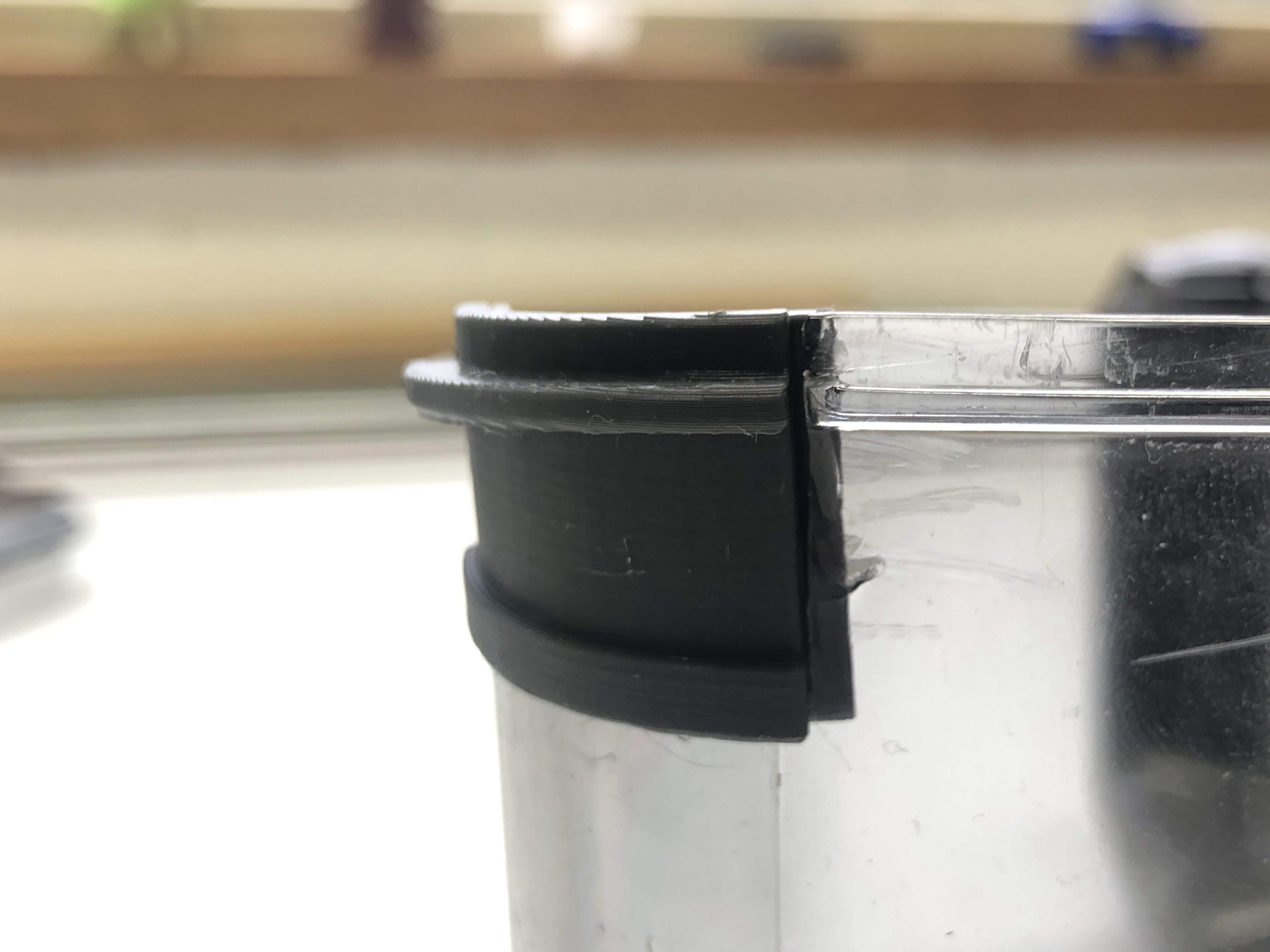
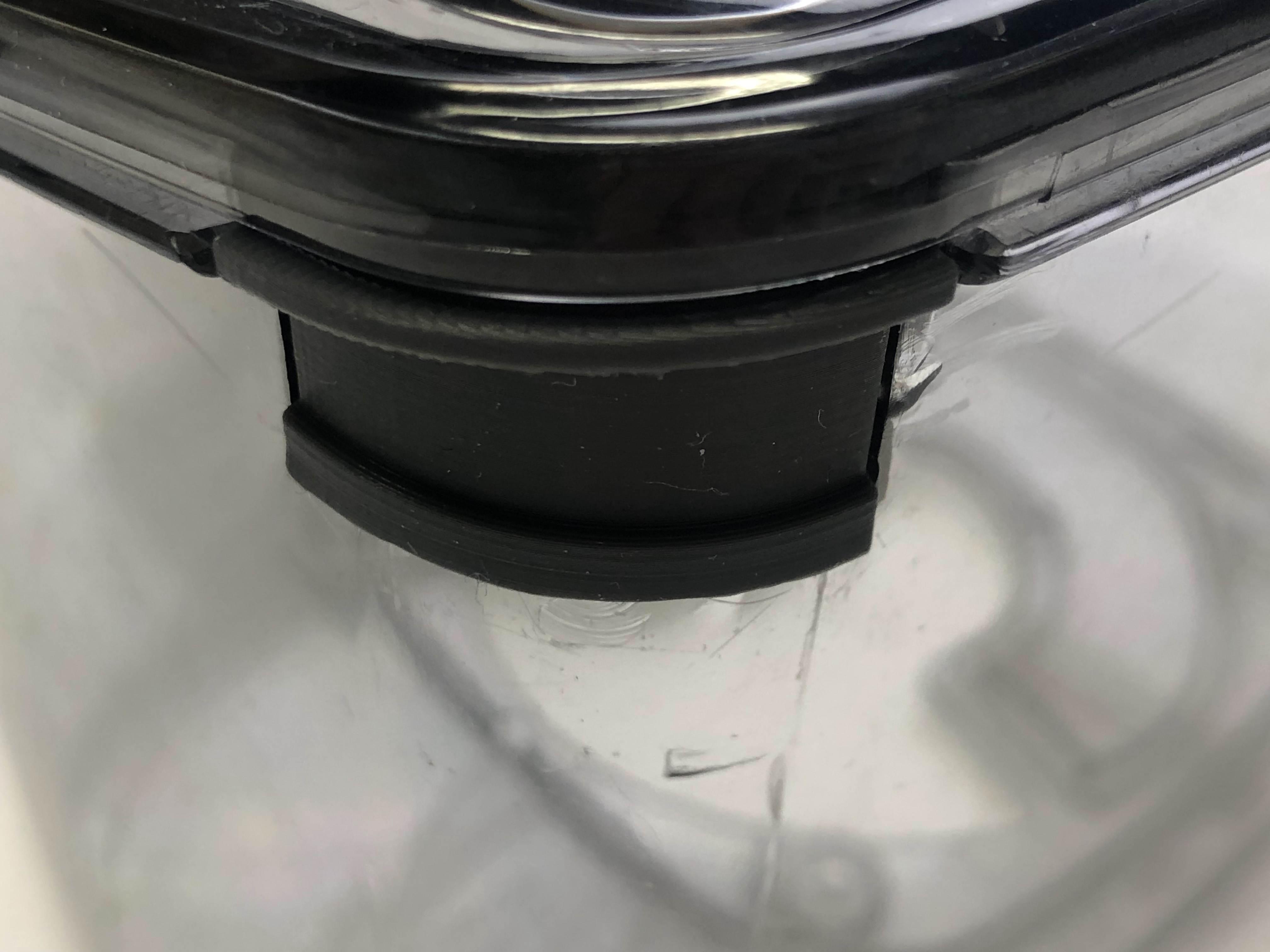
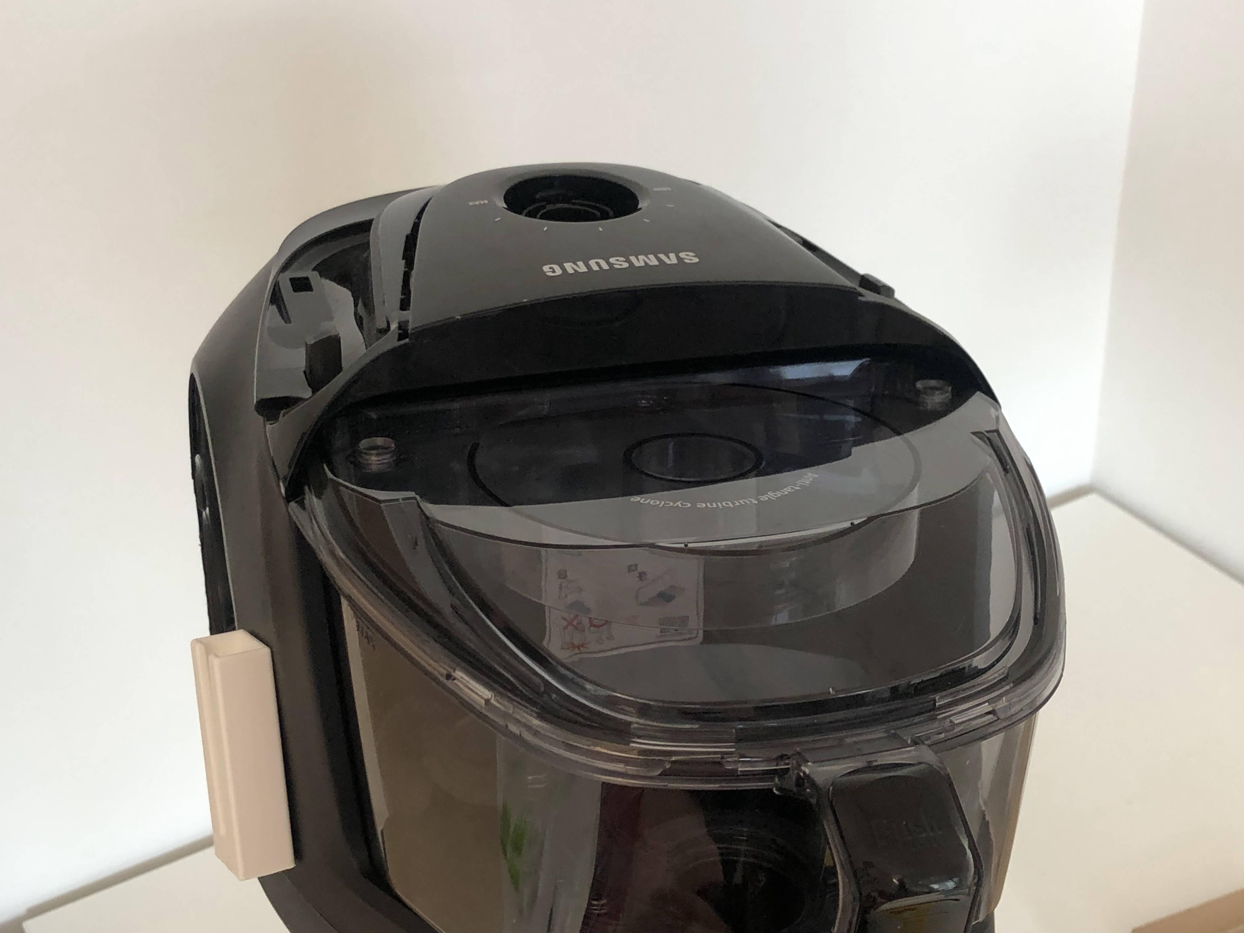
When testing the fit of the insert, make sure to test it with all of the parts that touch and/or surround it. As you can see in the pictures above for the case study, the insert was tested on the container itself, but also with the lid on top and finally with the entire container in the base of the vacuum cleaner.
Iterate!

Do not expect to fix your product with one single model, but use the power of iterations instead!
This guide is there to help you reach the goal in as little steps as possible, as fast as possible.
Do one iteration, test it, take your findings with you and improve with the next iteration. Keep the steps as simple as possible for as long as possible to be efficient with your time.
Optional / Additional Techniques

Please note that the picture above shows post-processing on a model that is not related to this instructable!
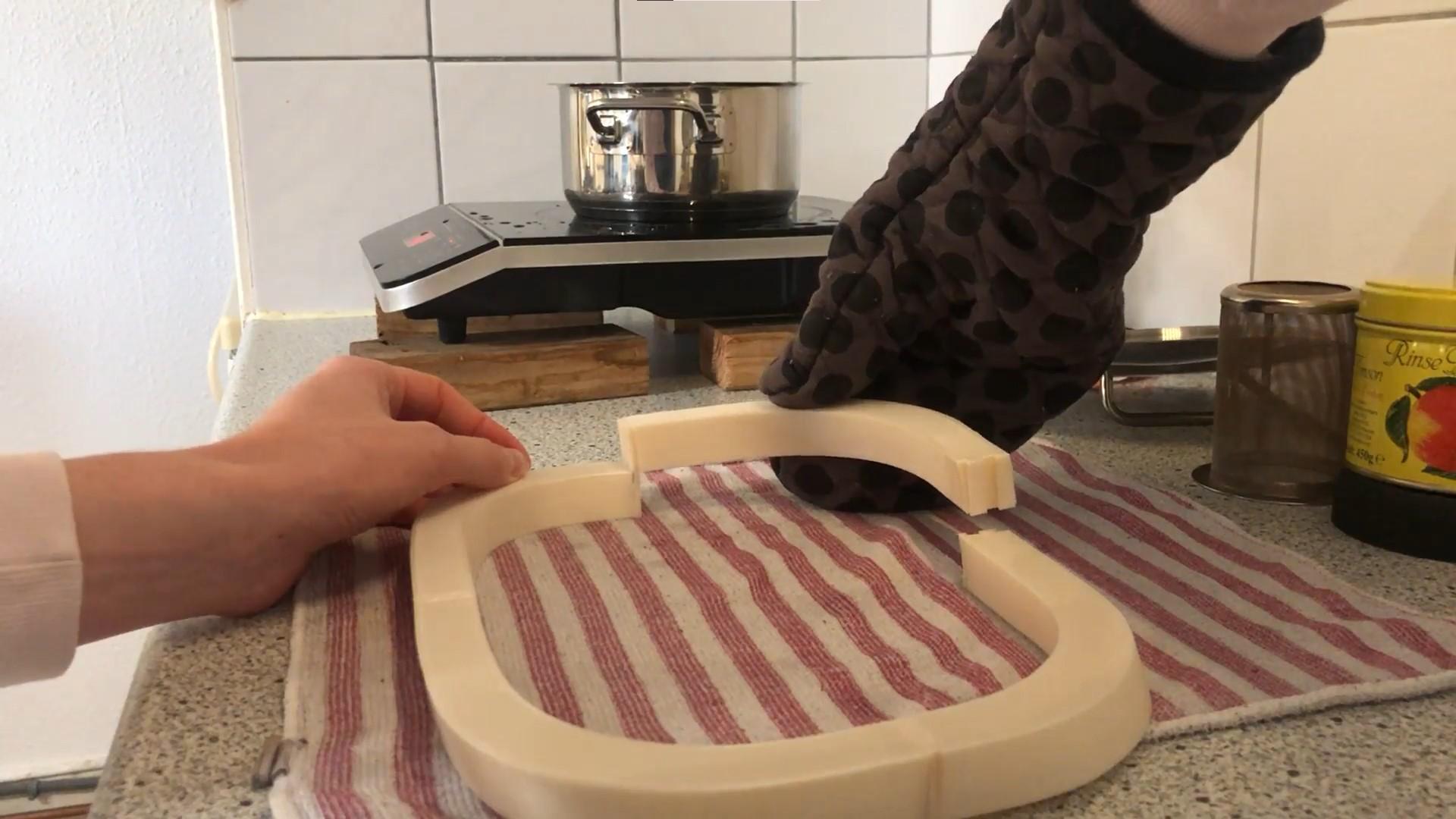
Assembly using boiling water
A useful tip for testing and assembly of the insert is to use a pot of boiling water. If you feel like your insert is very close to fitting, but just a little too tight to get it in place, it may help to hold your printed model in boiling water for 5 to 10 seconds and then immediately putting the part into place. The boiling water will soften the plastic slightly, giving you the opportunity to push the insert in place before the plastic hardens again. Be careful if you do this with small parts and use pliers and gloves accordingly!
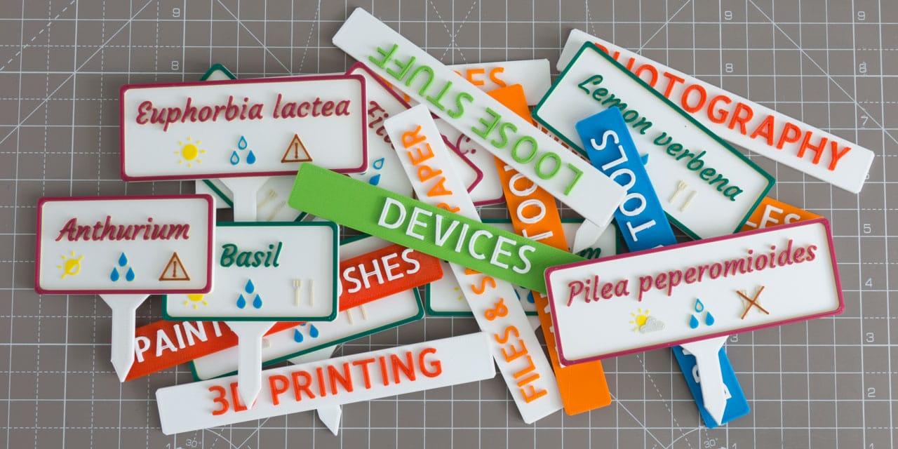
Personalisation by pausing at height
If you would like to personalize your broken part by giving it your own touch while repairing, you might be interested in the "pause at height" method, to change colours of filament throughout the print. You can use this function to create rows of different colours in your print, or make letters pop as the images above show.
Be creative and good luck with your project!