Private PC Power Button

Ever feel annoying when your Sisters, Brothers or Friends visit your room and take control of your PC? Well, password on login an multiple users on latest Operating-Systems will sort out this problem won't they?
Well, in my case, I had once try multiple users on my PC, but I install apps only for the Administrator (that was me). Installing apps for all users will take more spaces and create more folders to maintain the different user's files. So now you see my problems are :
- Visitor need to use apps that is not installed for "guest", so they still need my login.
- I have so little visitors asking permission to use my PC. So I think login on my private PC is annoying.
- Brothers/Sisters just break in my room and take over my PC. Moreover they are curios about what private files you have on your PC.
Hard to say "NO" isn't it? Because you will be stamped "stingy" on your forehead. Well, that is just a scenario in my head, but I bet some of you will feel exactly as I describe :D
Now you can move the "power button" to your Android phones. Watch this video :
Interesting? Now let's get started.
Bill of Materials
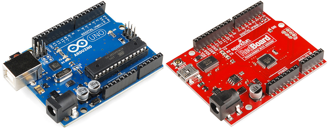
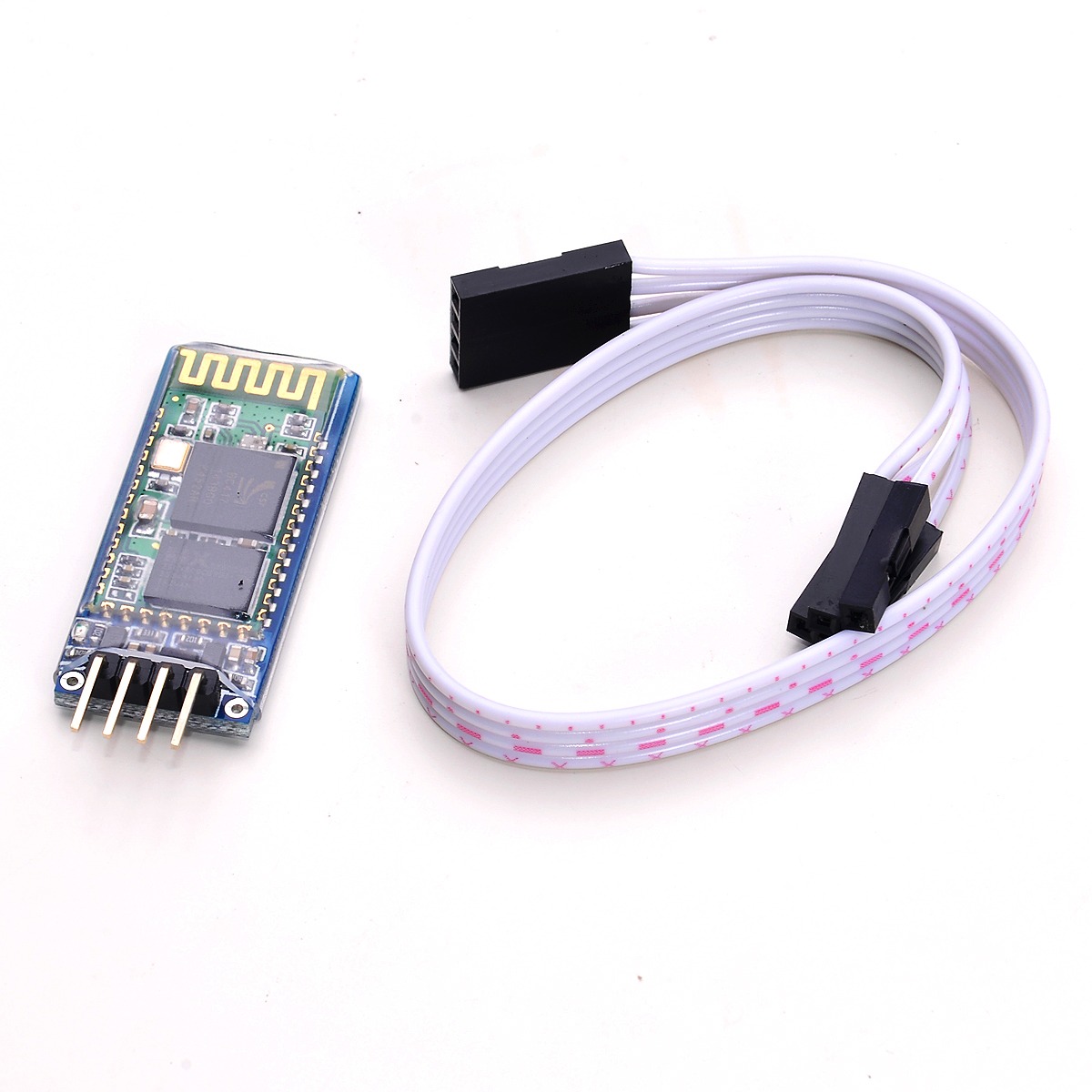
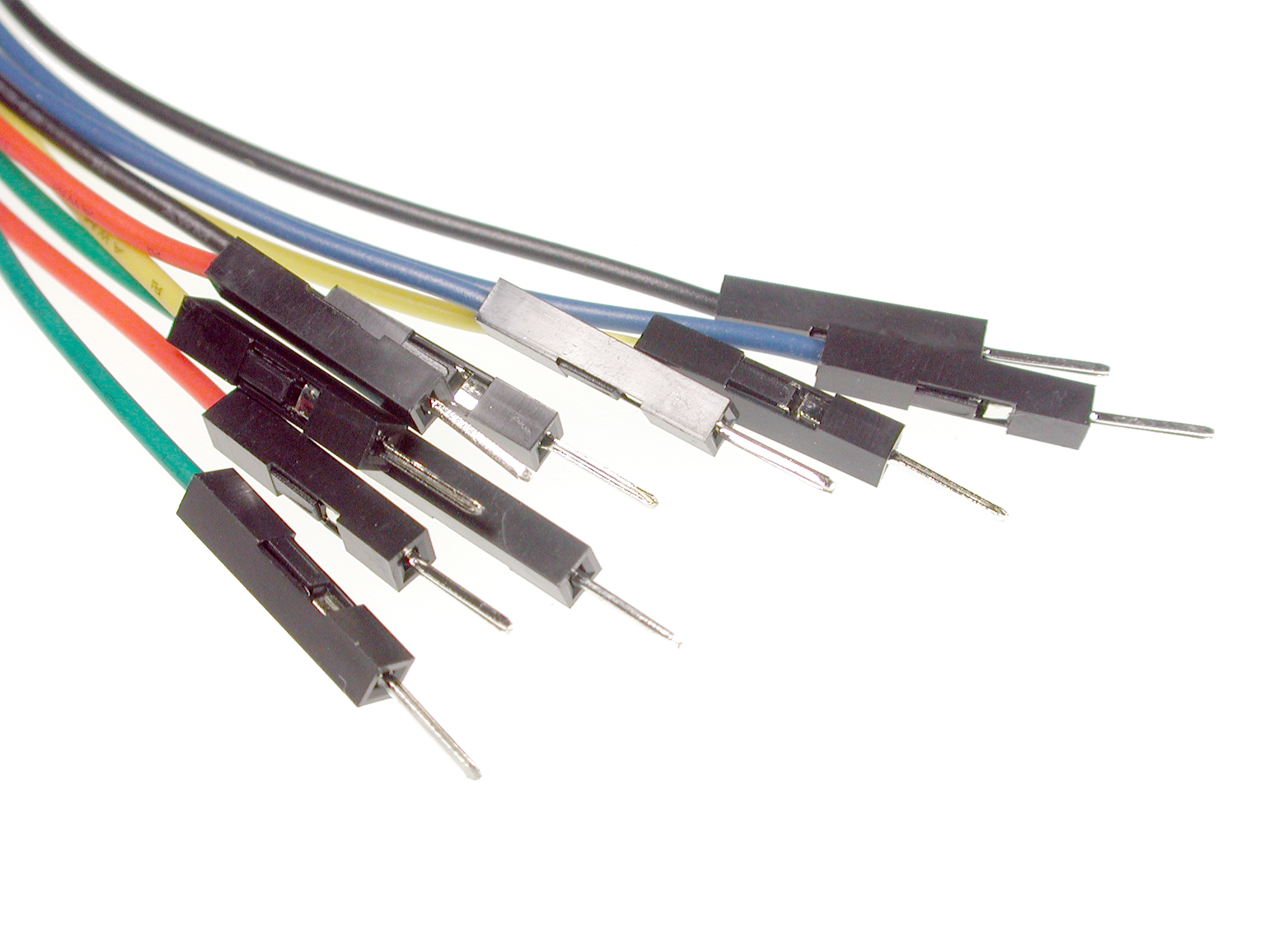
- A Sparkfun Redboard / Arduino Uno
- JY-MCU bluetooth module / HC-06
- Some breadboard jumper wires.
- And obviously a PC to hack.
Breakout JY-MCU Pin
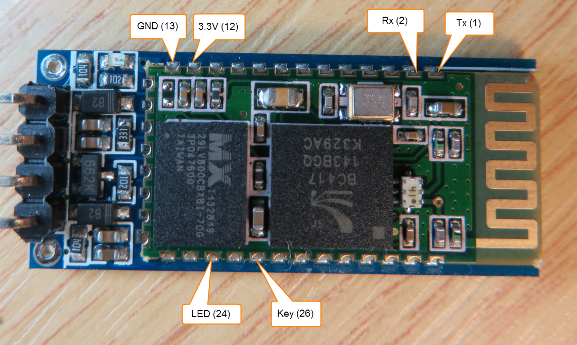
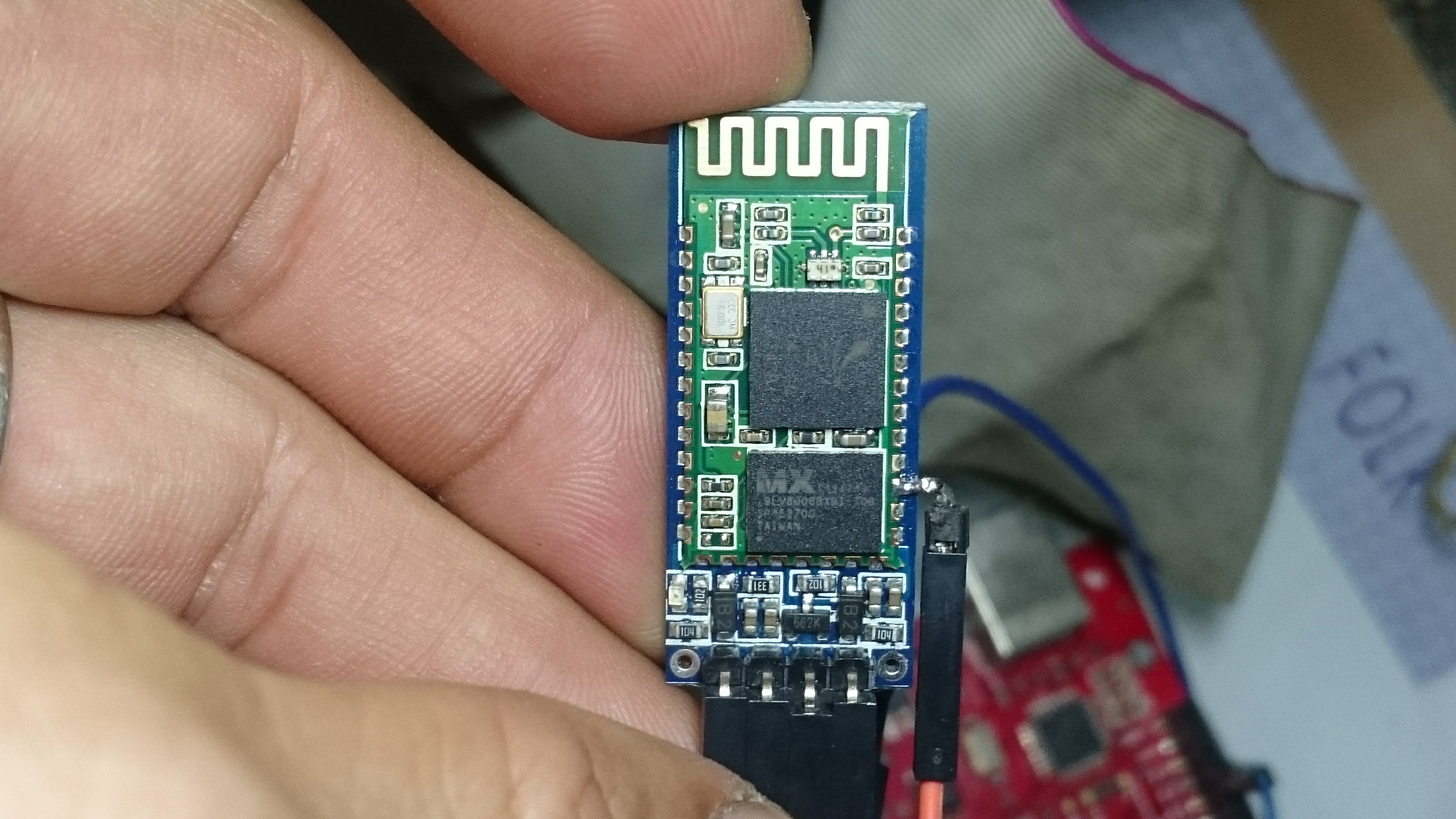
Status LED is on pin 24. You need to remove the plastic cover to access the pins. Place the antenna on top, pin 24 is at the right side, the third pin from bottom. Solder a female header or a jumper wire on it. I use this pin to figure out whether the bluetooth module is paired or not.
When it is not paired, the status led is blinking at around 35 ms. When it is paired, it will be on steadily. The Arduino is checking for Android command only when the bluetooth is paired.
Reveal ATX Cables
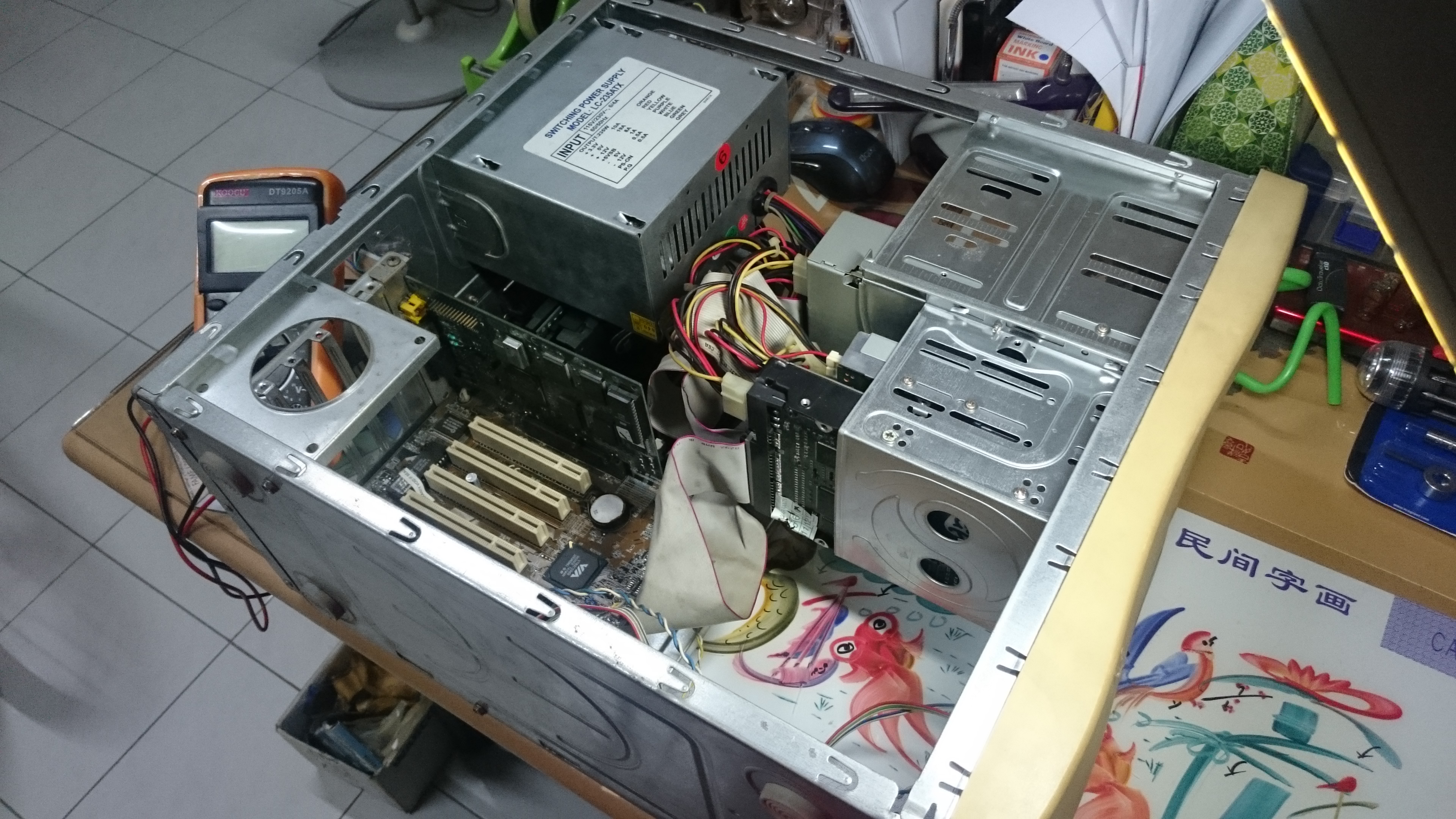
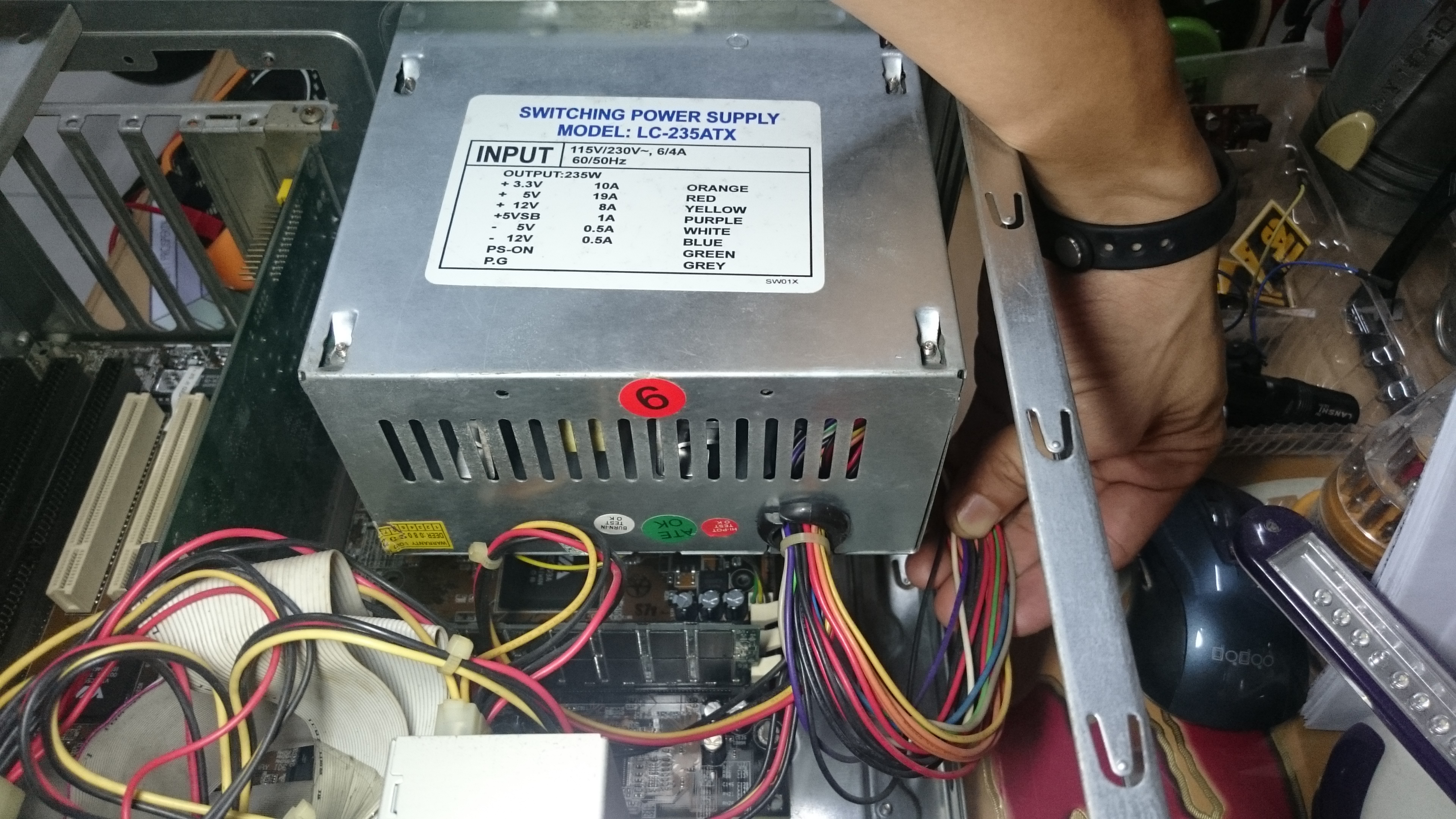
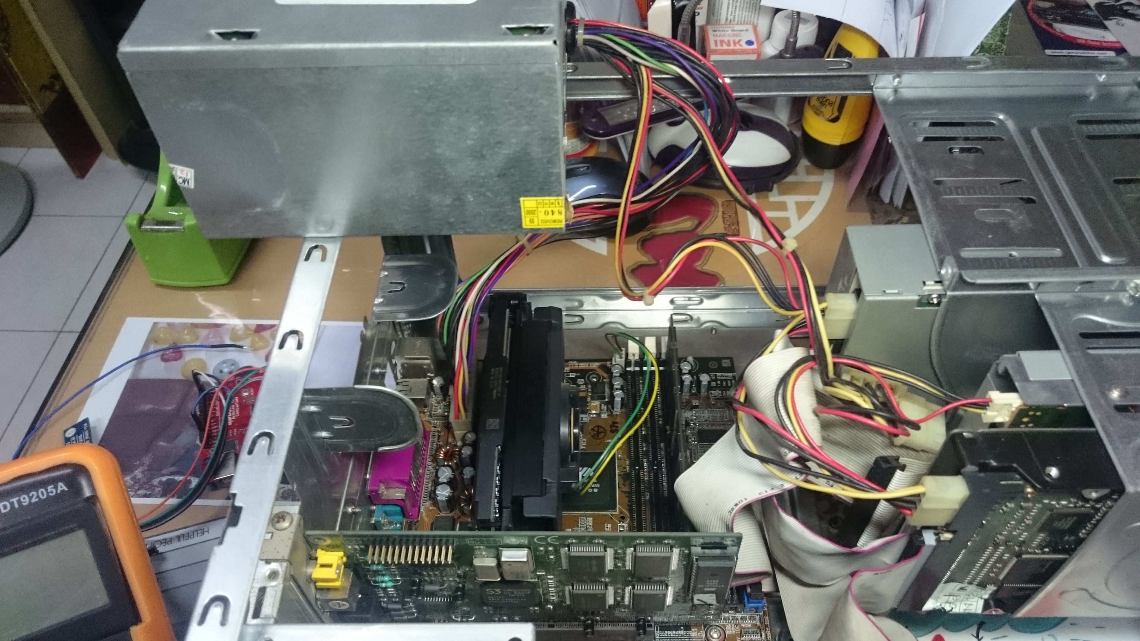
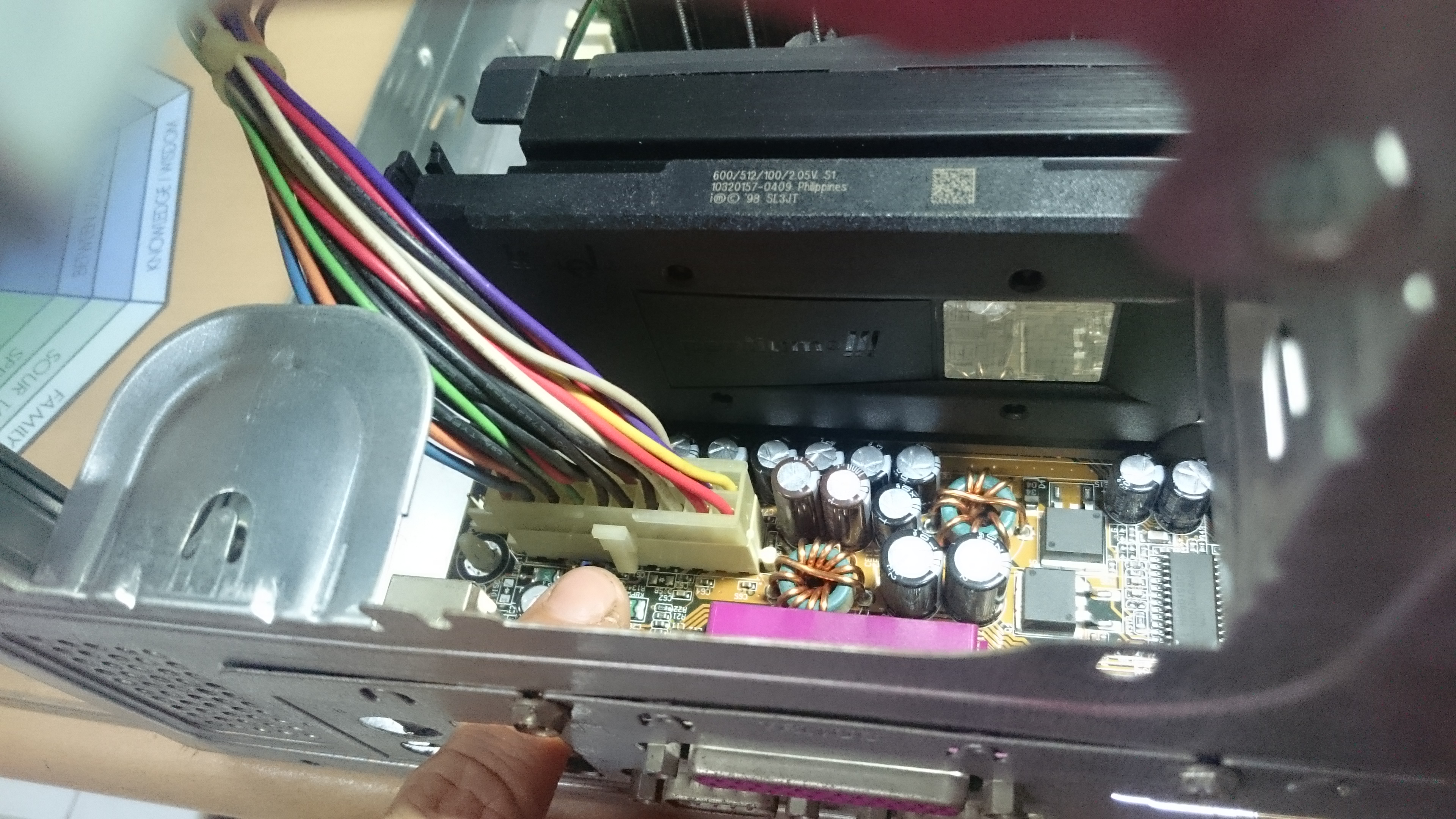
ATX has bunches of cables connected to PC devices. We are looking for the largest bunch connected to the motherboard. For some smaller cases it might be hidden under the power supply itself. It so, then you need to remove the power supply first to reveal the connector to motherboard.
Mount the Arduino
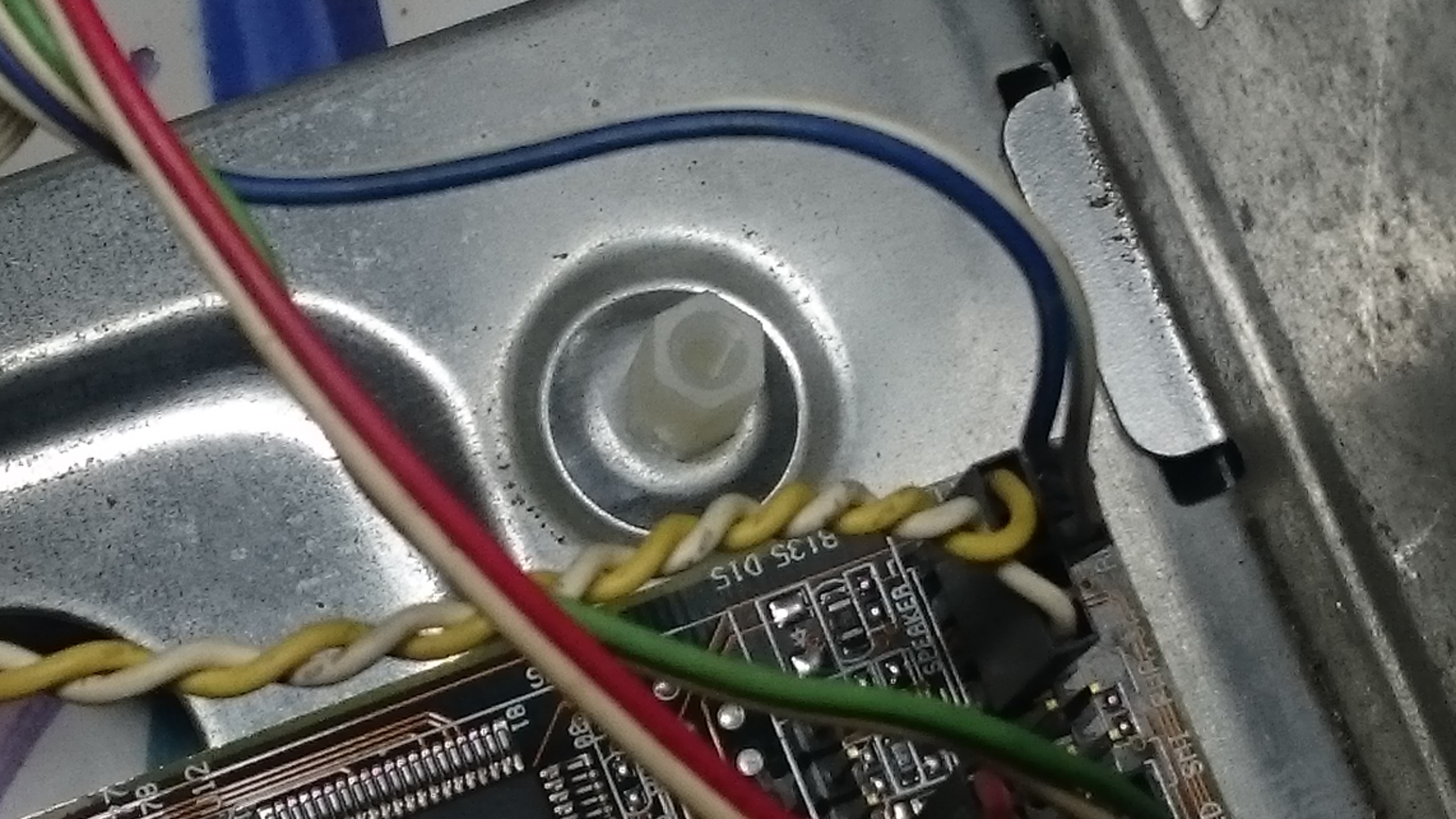
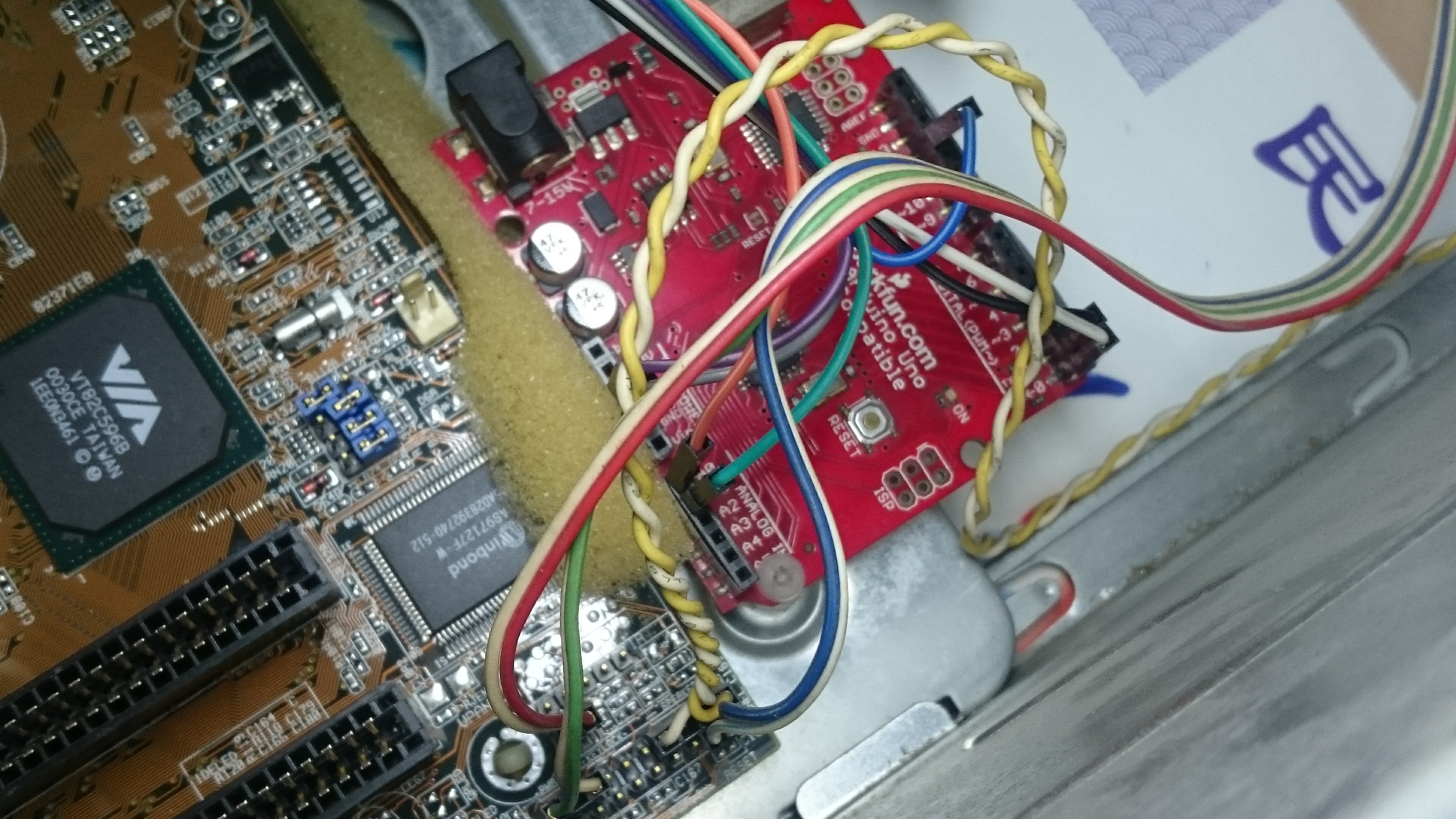
You can mount the Arduino on any of the case's hole. Use the same mounting as the motherboard, preferable plastic one to avoid short circuit to the metal part of the case.
You can simply put your Arduino on one of the drive slots available.
Wiring
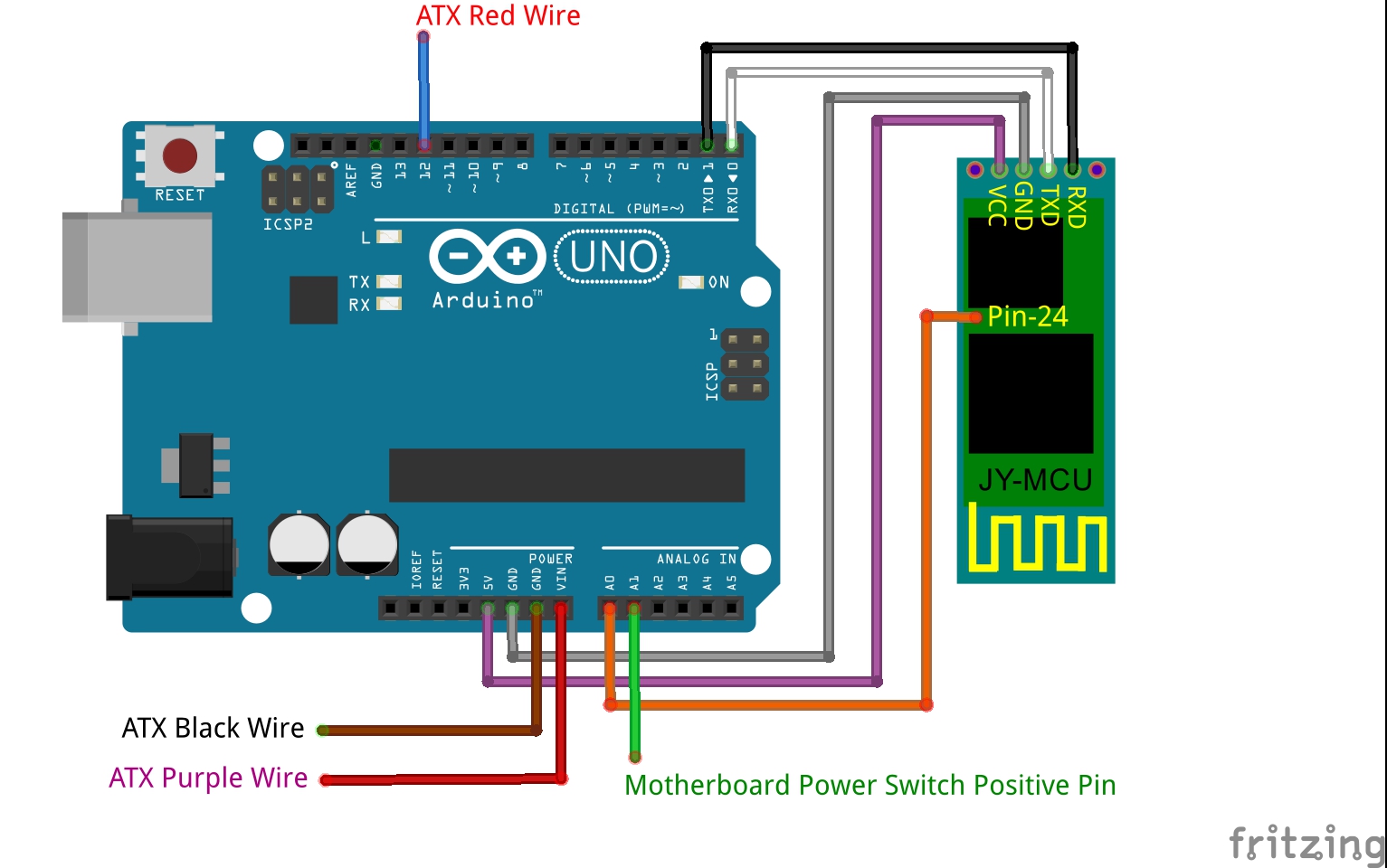
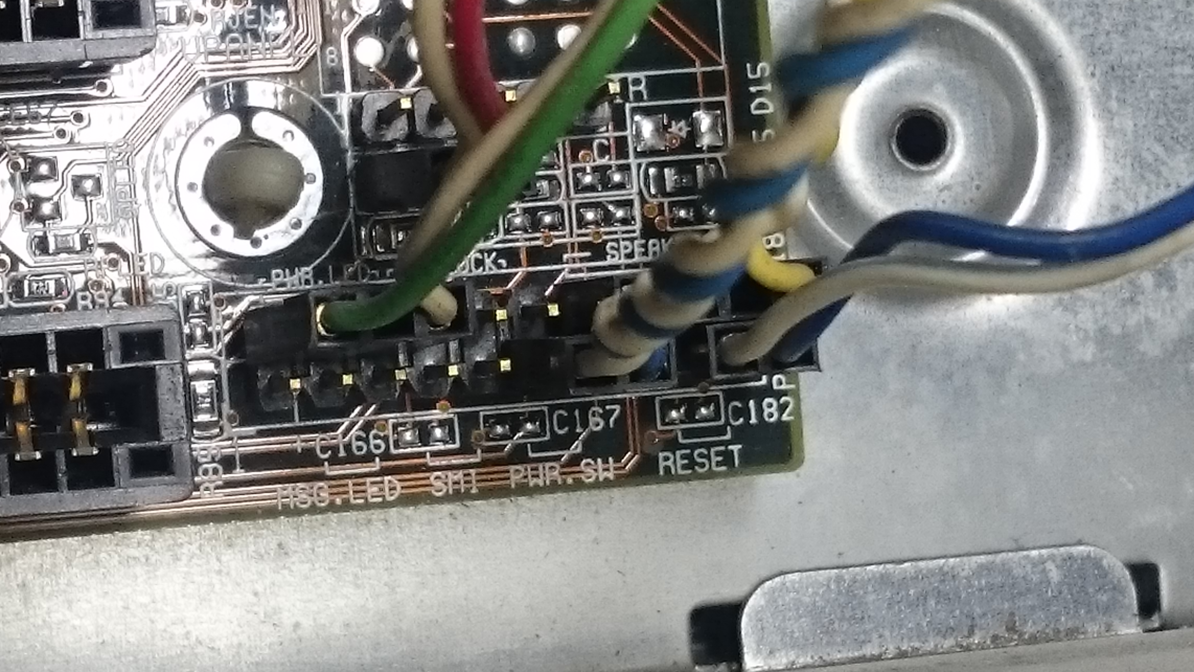
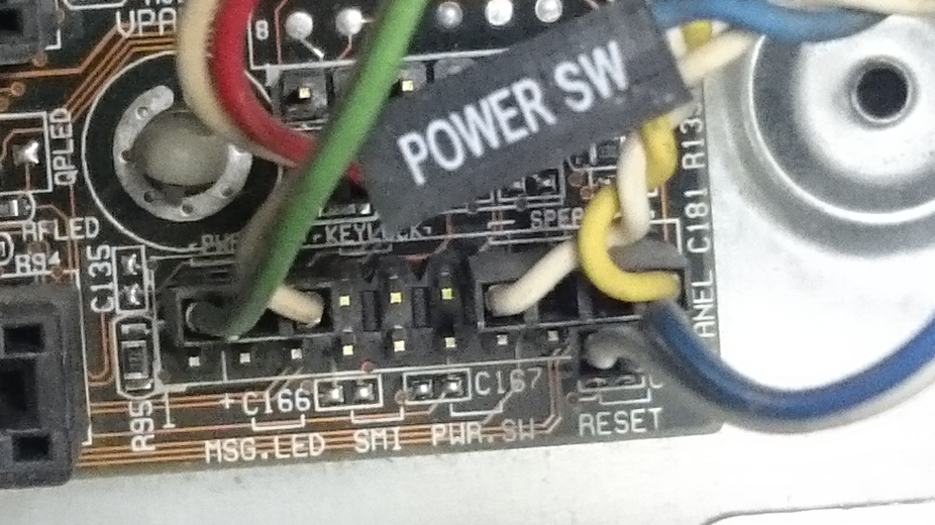
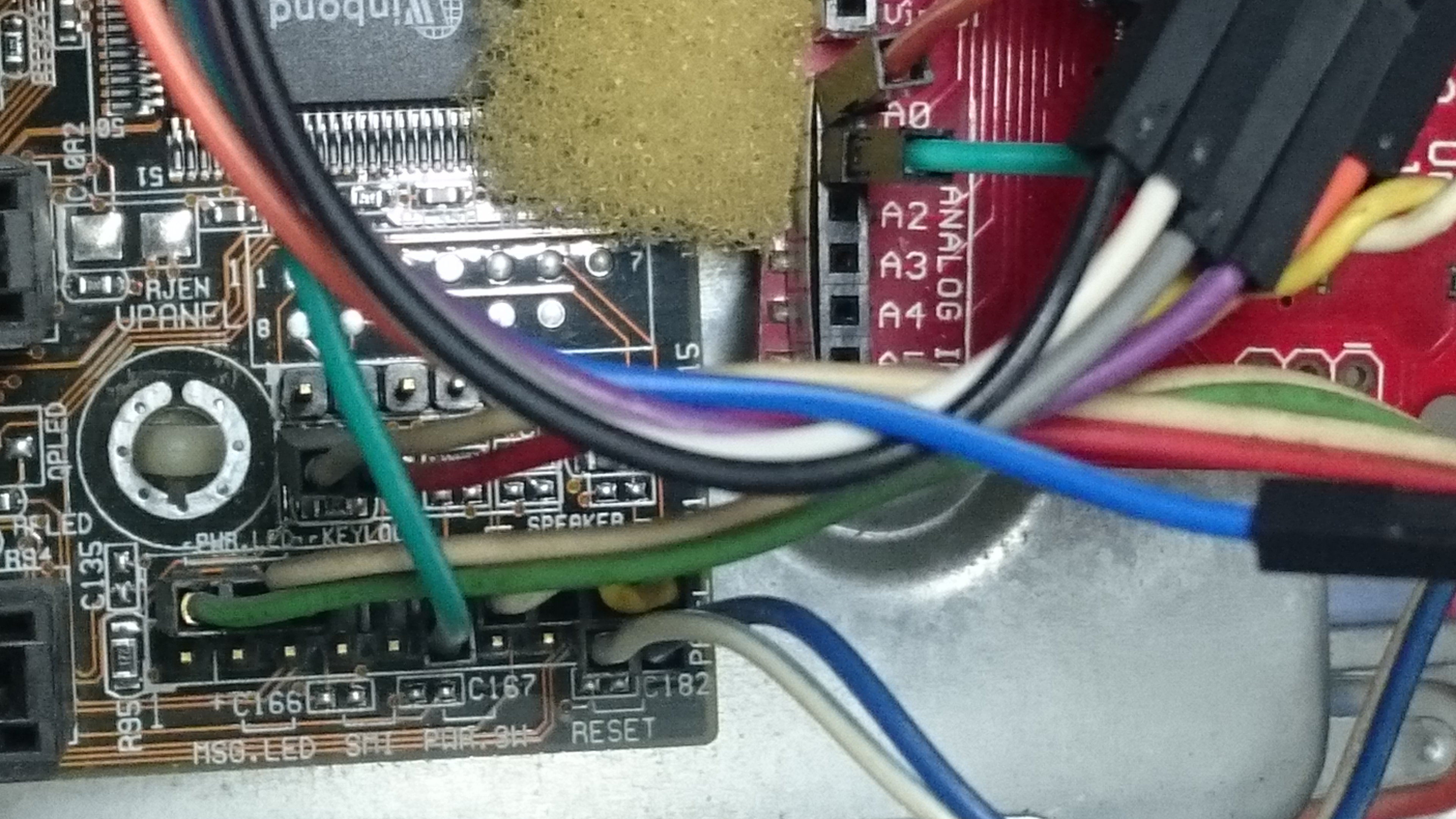
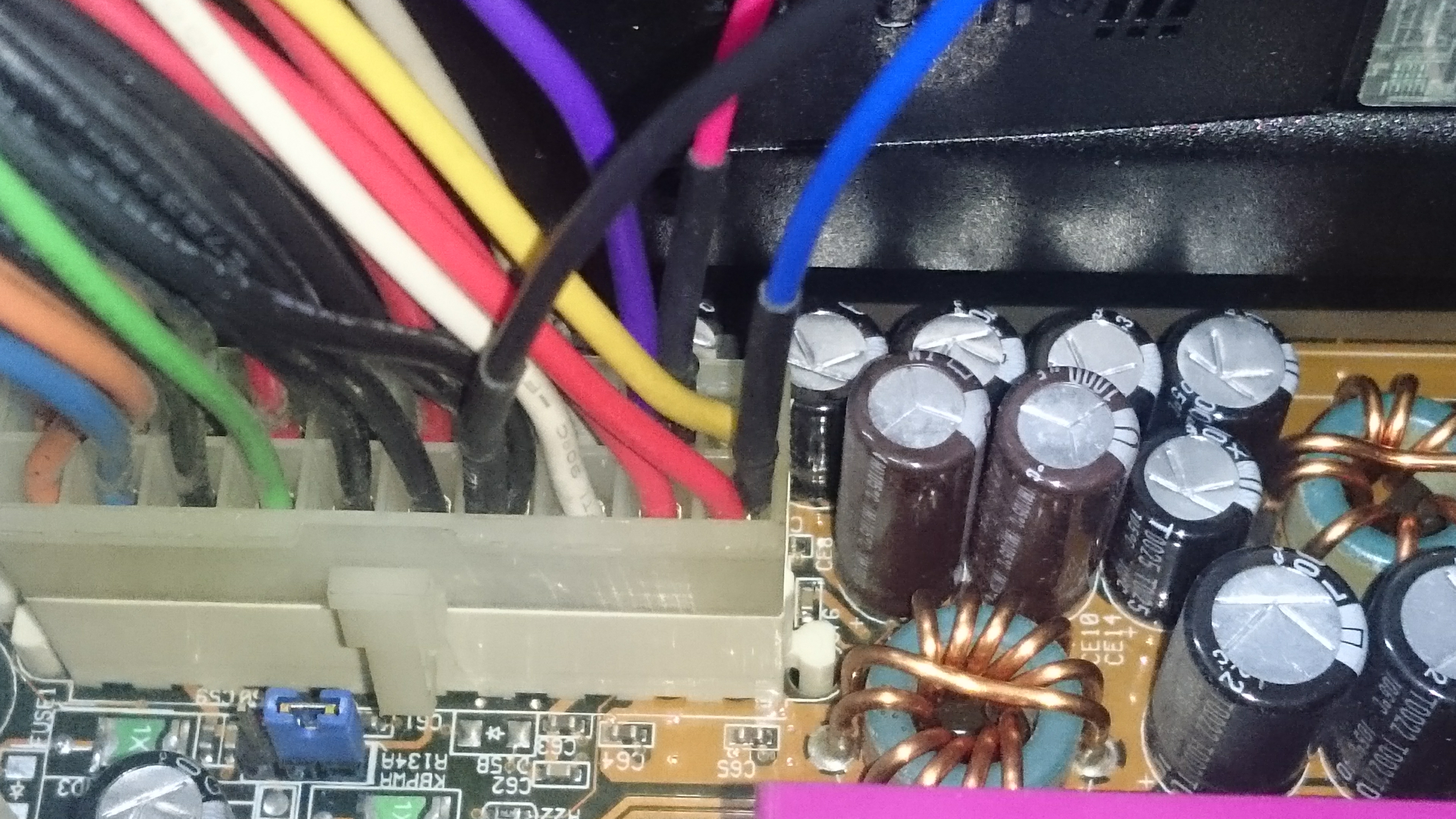
Refer to the wiring diagram above, I also write it down on the sketch, but I will still describe the wiring below :)
Wiring the JY-MCU Bluetooth Module :
- Vcc to Arduino 5V
- GND to Arduino GND
- Breakout Pin-24 to Arduino A0
- TXD to Arduino D0 (Rx)
- RXD to Arduino D1 (Tx)
Wiring the Motherboard :
- Power Switch (+) to Arduino A1. There are two pins of Power Switch (usually written "PWR.SW") on the board. One pin is measured 3V and the other is 0V (GND). Shorting the 3V pin to GND is what the PC power button does. 3V pin is usually placed near the back of the motherboard. You can check with your DMM and make sure your CPU is plugged in the wall wart to make sure which is which.
Wiring the ATX :
- Connect any black wire with a jumper wire to Arduino GND.
- Connect the purple wire with a jumper wire to Arduino Vin.
- Connect any red wire with a jumper wire to Arduino D12.
Shorten the Path (Optional)
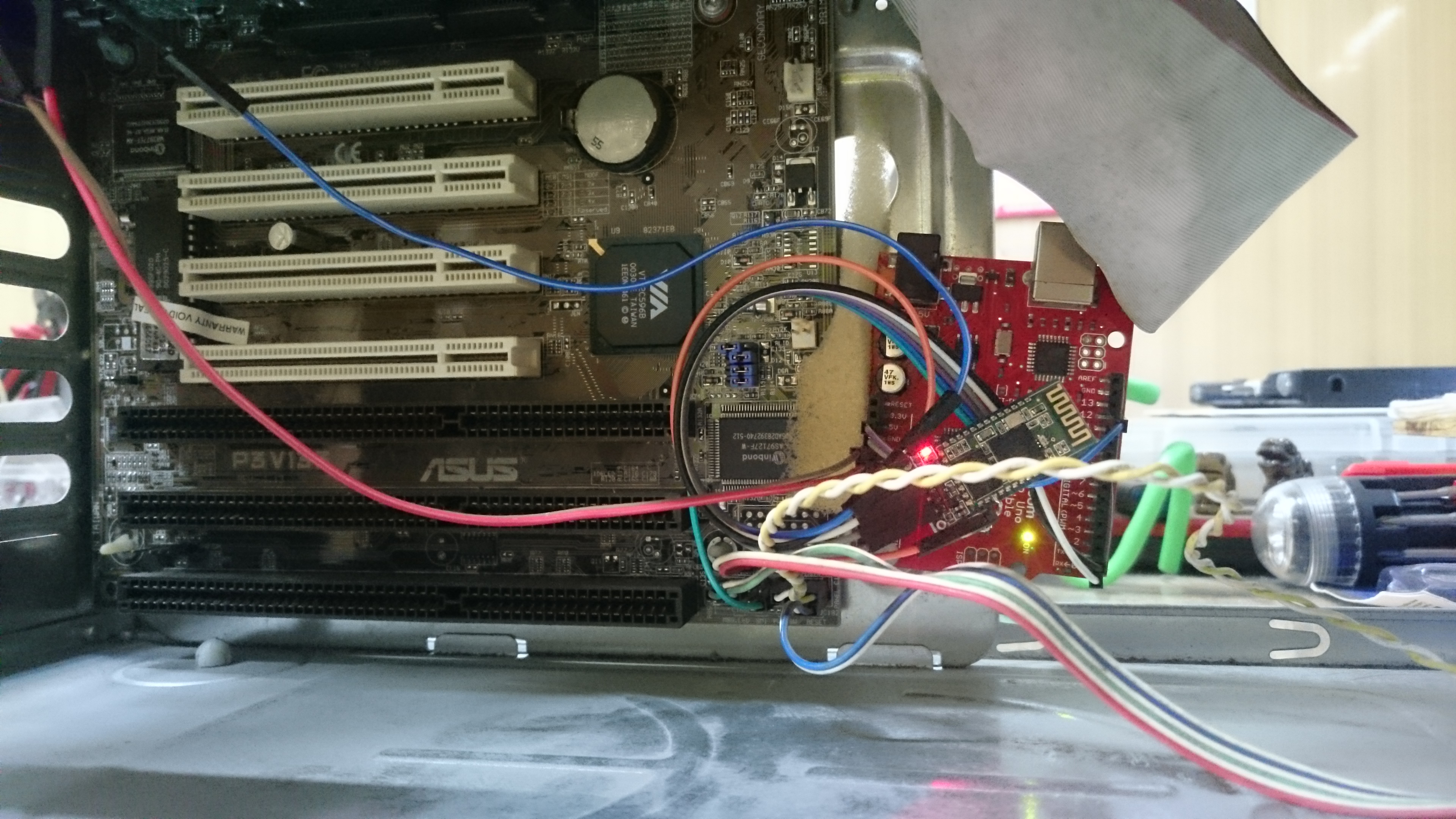
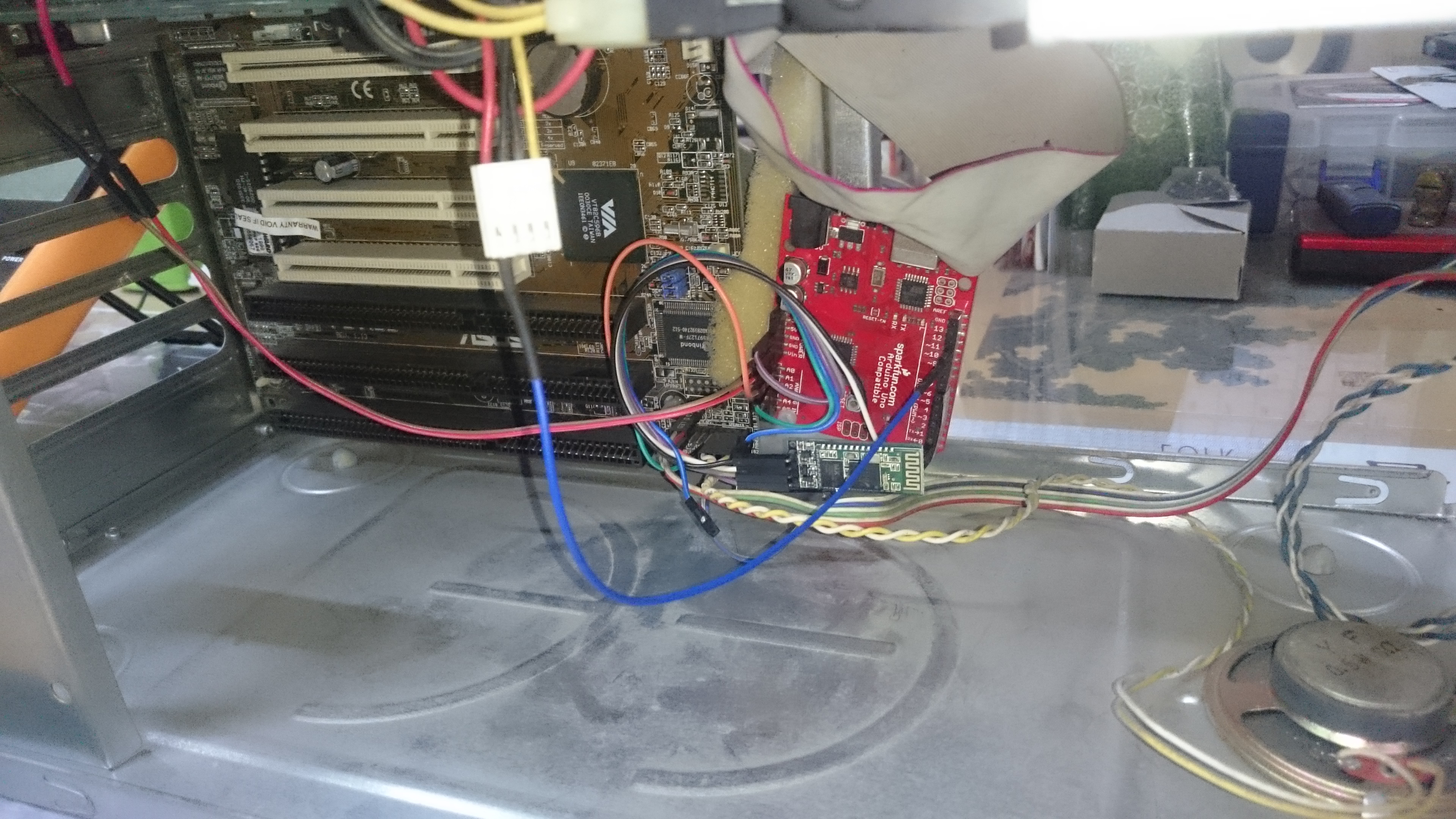
Instead of taking any red wire from the ATX big bunch wires, you can take any red wire that is grouped for floppy disk drive or other optical drives. We use this red wire of ATX to detect either the PC is ON or OFF. Red wires only read 5V when the PC is ON.
Coding the Arduino
/*
 * Private PC Power On Key
 * By Chienline @2016
 *
 * This sketch is used along with ArduinoBluetoothPCPowerOn.apk to present your PC power button on your Android phone.
 * Arduino Uno with JY-MCU HC-06 Bluetooth Module is connected to your PC's Motherboard and ATX power supply.
 *
 *   Wiring :
 * |-----------|-------------|---------------|-------------|
 * |  Uno      |  HC-06      |   Mobo        |   ATX       |
 * |-----------|-------------|---------------|-------------|
 * |  5V       |  VCC        |               |             |
 * |  GND      |  GND        |               |             |
 * |  GND ---- | ----------- | ------------- |-> Black     |
 * |  Vin ---- | ----------- | ------------- |-> Purple    |
 * |  A0       |  Pin-24     |               |             |
 * |  A1  ---- | ----------- |-> PowerSW(+)  |             |
 * |  D0       |  TXD        |               |             |
 * |  D1       |  RXD        |               |             |
 * |  D12 ---- | ----------- | ------------- |-> Red       |
 * |-----------|-------------|---------------|-------------|
 *
 * The power button with "5" on it means pressing the button for 5 seconds.
 *
 */

char incomingByte;  // incoming Char;
String inText; // incoming Text;
int AtxPowerPin = 12; // Detecting The Power State of ATX;
int MoboPowerPin = A1; // Read PC Power pin on Motherboard. Set this pin LOW to turn on PC;
int BtPairPin = A0; // Checkiing the pairing state of BT;
String PcStatus = "OFF"; //State of PC either ON or OFF;
boolean Paired = false;
int i;

unsigned long previousMillis = 0; // last time update
unsigned long currentMillis = 0;
long interval = 2000; // interval at which to do something (milliseconds)

void setup() {
  Serial.begin(9600); // initialization
  pinMode(AtxPowerPin, INPUT);
  pinMode(MoboPowerPin, INPUT);
  pinMode(BtPairPin, INPUT);
}

void loop() {
  //Checking if phone is paired;
  Paired = false;
  for(i=0; i < 10; i++){
    if (analogRead(BtPairPin) < 700){
      Paired = false;
      break;
    }
    else {
      Paired = true;
    }
    delay(20);
  }

  if (Paired){ //if paired, check ATX status and send to phone;
     if (digitalRead(AtxPowerPin) == HIGH){
       PcStatus = "ON";
     }
     else{
       PcStatus = "OFF";
     }
     Serial.print(PcStatus); //Send PcStatus to phone;
     delay (2000); //Interval for sending PcStatus to phone;

     //Check for incoming text from phone;
     while (Serial.available() < 1) {return;}  // if no incoming data, return to loop();
     incomingByte = Serial.read(); // read incoming Character;
     if (incomingByte != '#'){
        inText += incomingByte;
     }
     else {
       if (inText == "ONCE"){
         pinMode(MoboPowerPin, OUTPUT);
         analogWrite(MoboPowerPin, 0); //press power button once;
         delay (100);
         pinMode(MoboPowerPin, INPUT);
       }
       else if (inText == "FIVESEC"){
         pinMode(MoboPowerPin, OUTPUT);
         analogWrite(MoboPowerPin, 0); //press power button for 5 seconds;
         delay (5200);
         pinMode(MoboPowerPin, INPUT);
       }
       inText = "";
     }
   }
}
Android Application
This is my first time building Android Application with the MIT AI2 APP INVENTOR. I am modifying a bluetooth connection sample app.
How to use :
- Download and install the apk file on your android phone.
- Open your phone bluetooth settings.
- Pair your phone with JY-MCU Bluetooth device.
- Open the app with black and white power button icon.
- Click on the "Not Connected" button and choose your JY-MCU bluetooth.
- When the button has turned to "Connected" then you are ready to use the power button.
Note :
There is delay time from the time you press the button until the PC is turned ON, so be patient :)
Press "once-button" takes about 2 to 3 seconds to execute while the "5-second-button" takes about 12 seconds to execute.
The delay time is intended to minimize the Arduino checking routine, because we only need to turn the PC ON/OFF let's say 3 to 5 times a day, while the Arduino needs to run its checking routine all the time. I also reduce its work to check only when the bluetooth is paired, that's why we break out bluetooth pin-24 for this task. I don't know if it really reduce the Arduino's work, as we are checking the bluetooth pairing instead of incoming serial communication from bluetooth. Well.. this is a fun project for me anyway. I also attach the .aia file for AppInventor and you can improve it your way :)