Printing and Assembly Guide of the Soviet N-1 Rocket
by Kmobrain in Workshop > 3D Printing
1871 Views, 17 Favorites, 0 Comments
Printing and Assembly Guide of the Soviet N-1 Rocket
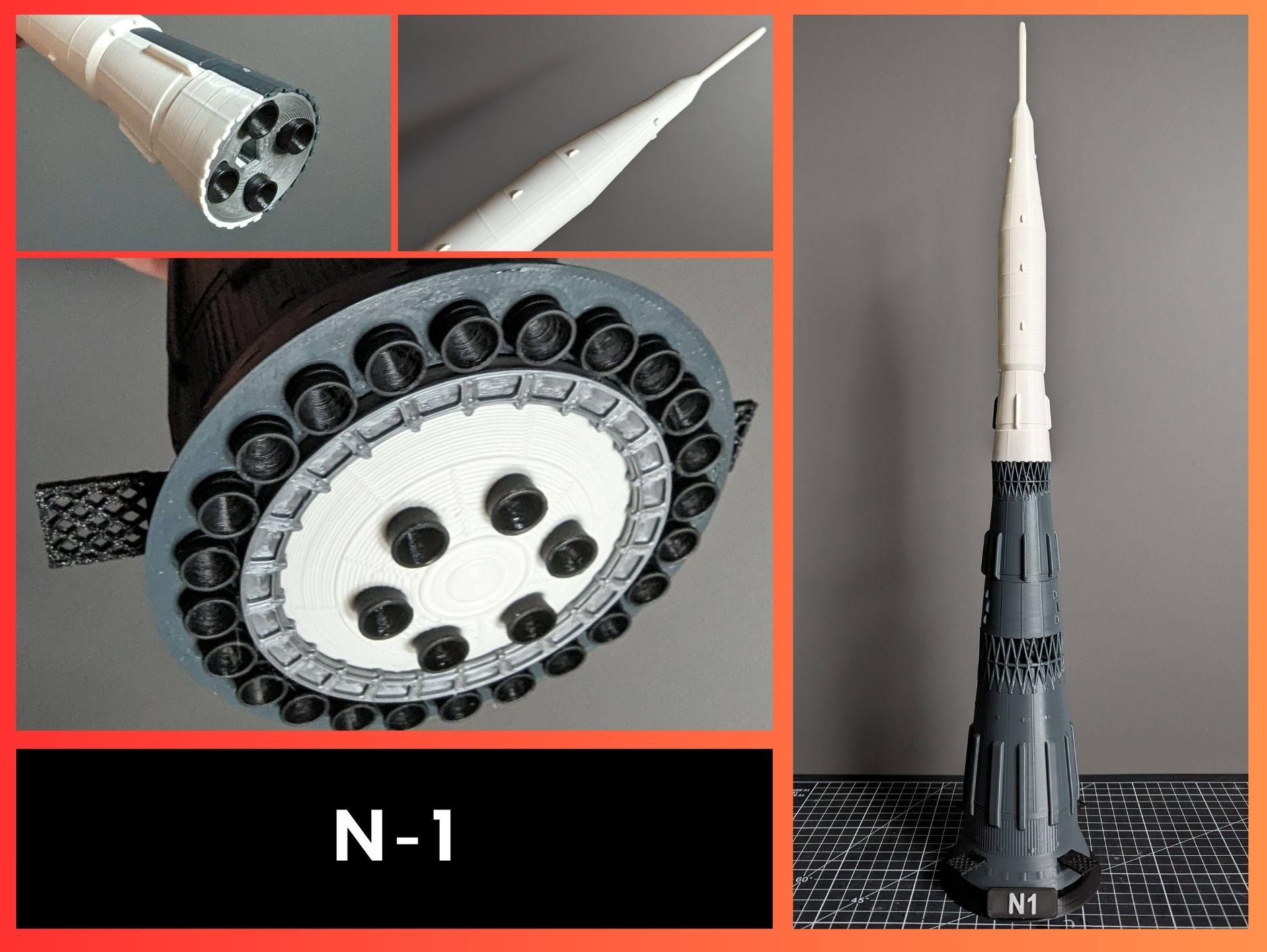
Here's a guide to printing my model of the Soviet N-1 rocket.
In this guide you will be guided through the correct positioning of the parts on the board, the settings in the Slicer and the assembly of the model.
Supplies
Here's the material used in this guide.
- 3D Printer
- 3D Slicer
- 3D files of my N-1 model available on Printables modeled with Fusion360.
- Black Filament
- Grey Filament
- Metal Filament
- White Filament
- Glue
The Slice
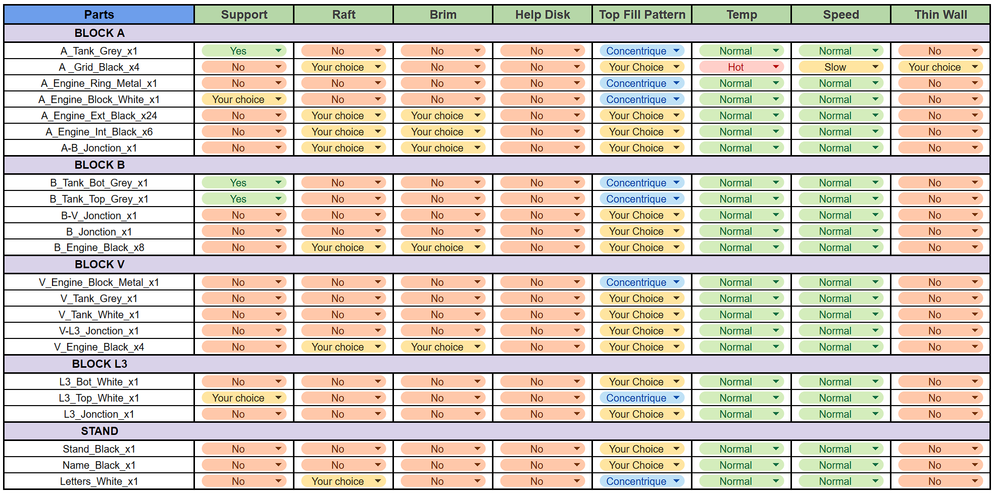
PRINCIPLE OF THE TABLE
I've divided the slice steps into 'blocks' corresponding to the stages of the rocket, but you can do the slice in any order you like.
In each slice step you'll find a table with my advice on a number of parameters.
- The Supports will be in green in the slicer images, and I'll also put a note in the image.
- The Rafts, Brim and HelpDisk will be selected according to your usual settings in case your parts come unstuck.
- The Top Fill pattern is for a prettier result, but you can choose whatever you like.
- Temperature and Speed can be modified for certain parts, but your usual settings may also be valid.
- Thin walls can be activated on certain parts, but as with temperature and speed, your usual settings may also be valid.
IMPORTANT
For "Jonction" parts, I advise you to print as tightly as possible, adding 1% by 1% to the scale to ensure perfect assembly.
Slice Block A
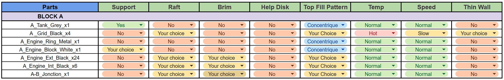
For "A_Grid_Black_x4" parts, the speed must be low and the temperature high to simplify printing, but your standard settings may be valid.
There are two possible configurations with "A_Grid_Black_x4":
- "UF_A_Grid_Black_x4" for unfolded grids.
- "A_Grid_Black_x4" for folded grids.
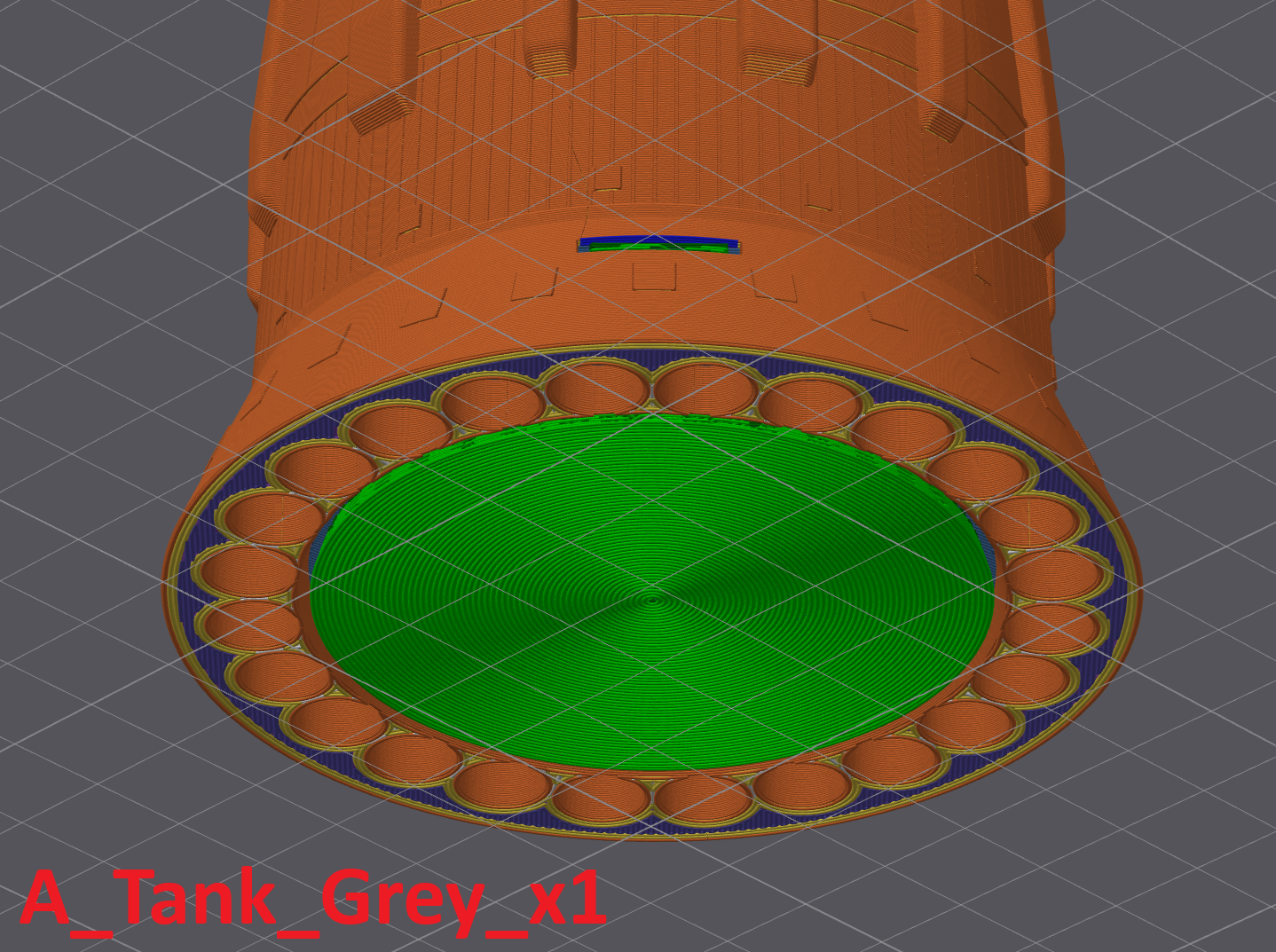
For the supports, I advise you to put 2 mm X/Y space between the part and the support.
- For "A_Tank_Grey_x1" you need to put support at the bottom of the model and in the slots provided for "A_Grid_Black_x4".
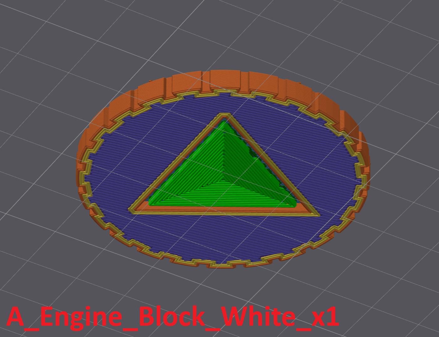
- For "A_Engine_block_White_x1" you also need support at the bottom of the model.
For the engines, if you can't print all the engines at the same time (to save time) you can try using a "Raft" if that still doesn't work you can print them "one by one".
Slice Block B
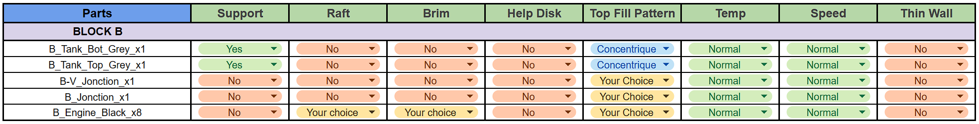
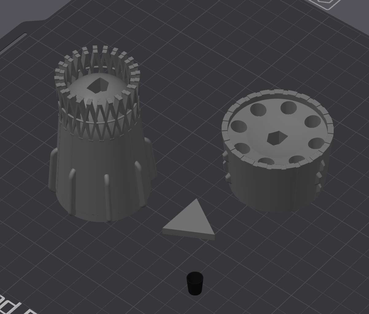
For the supports in Block B, same as in the previous step, I advise you to put 2 mm X/Y space between the part and the support.
The same applies to engines if you can't print all the engines at the same time (to save time) you can try using a "Raft" if that still doesn't work you can print them "one by one".
Slice Block V
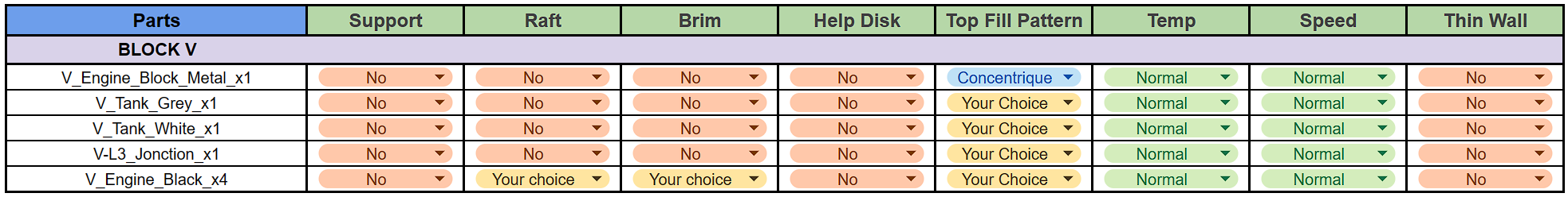
There is no need to make any particular adjustments to the parts in the Block V, except for the engines, which are the same as in the previous stages.
Slice Block L3

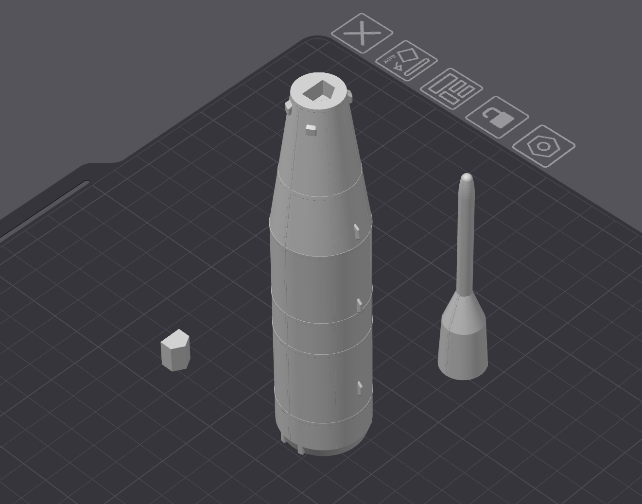
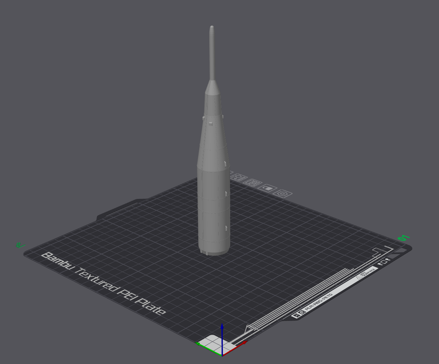
There are no special settings for "Bloc L3".
But there are two possible configurations.
- In two parts, "L3_Bot_White_x1" and "L3_Top_White_x1" with "L3_Jonction_x1" with a maximum height of 14 cm.
- In one part "L3_White_x1" with a maximum height of 22 cm.
Slice Stand

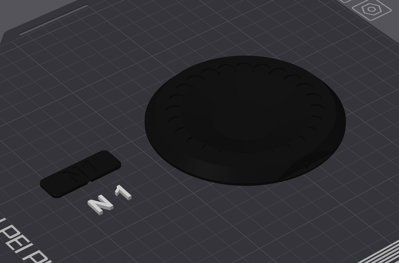
There are no special settings for "the Stand".
"Letters_White_x1" can be printed with a "Raft" to facilitate printing.
Assembly
The assembly steps will also be divided by Block, this time I advise you to follow the direction of the guide.
At the bottom right of each image there will be a step code, the letter for the Block and the number for the step, for example A1 for step 1 of Block A.
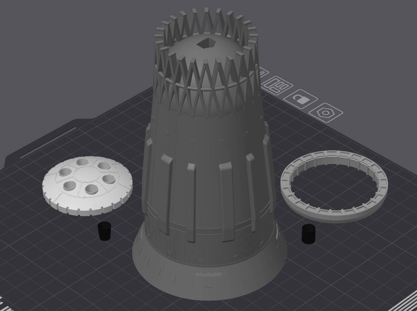
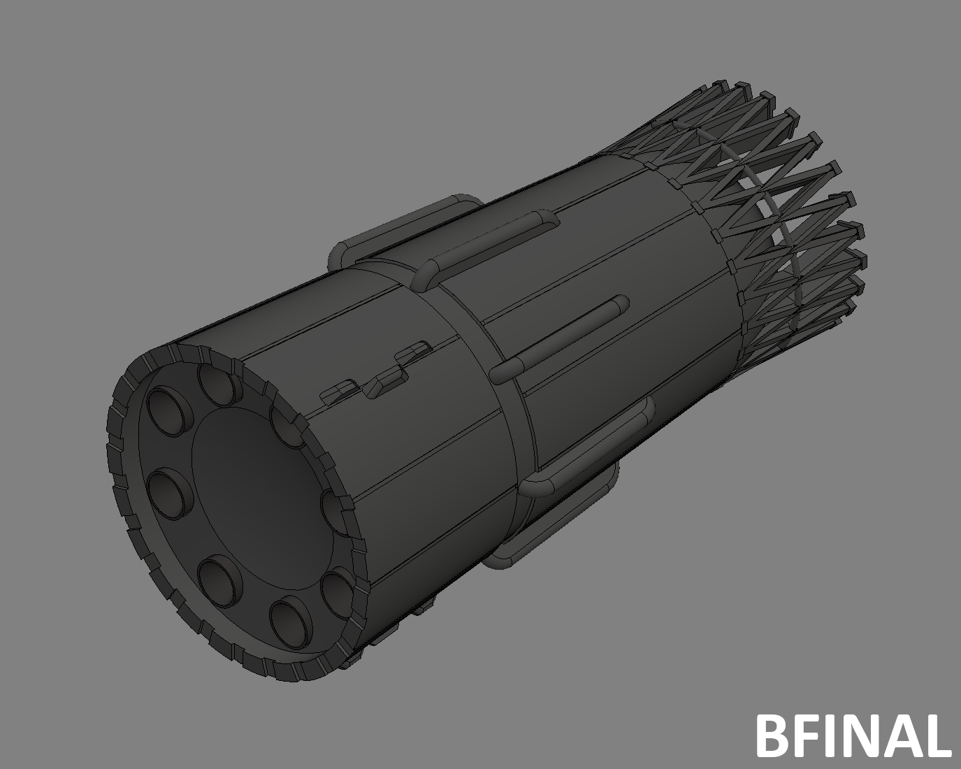
Assembly Block A
After removing the supports from the blocks "A_Tank_Grey_x1" and "A_Engine_block_White_x1" you can begin assembly.
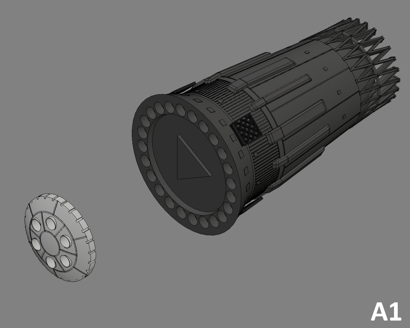
A1
- Glue "A_Engine_block_White_x1" to the bottom of "A_Tank_Grey_x1".
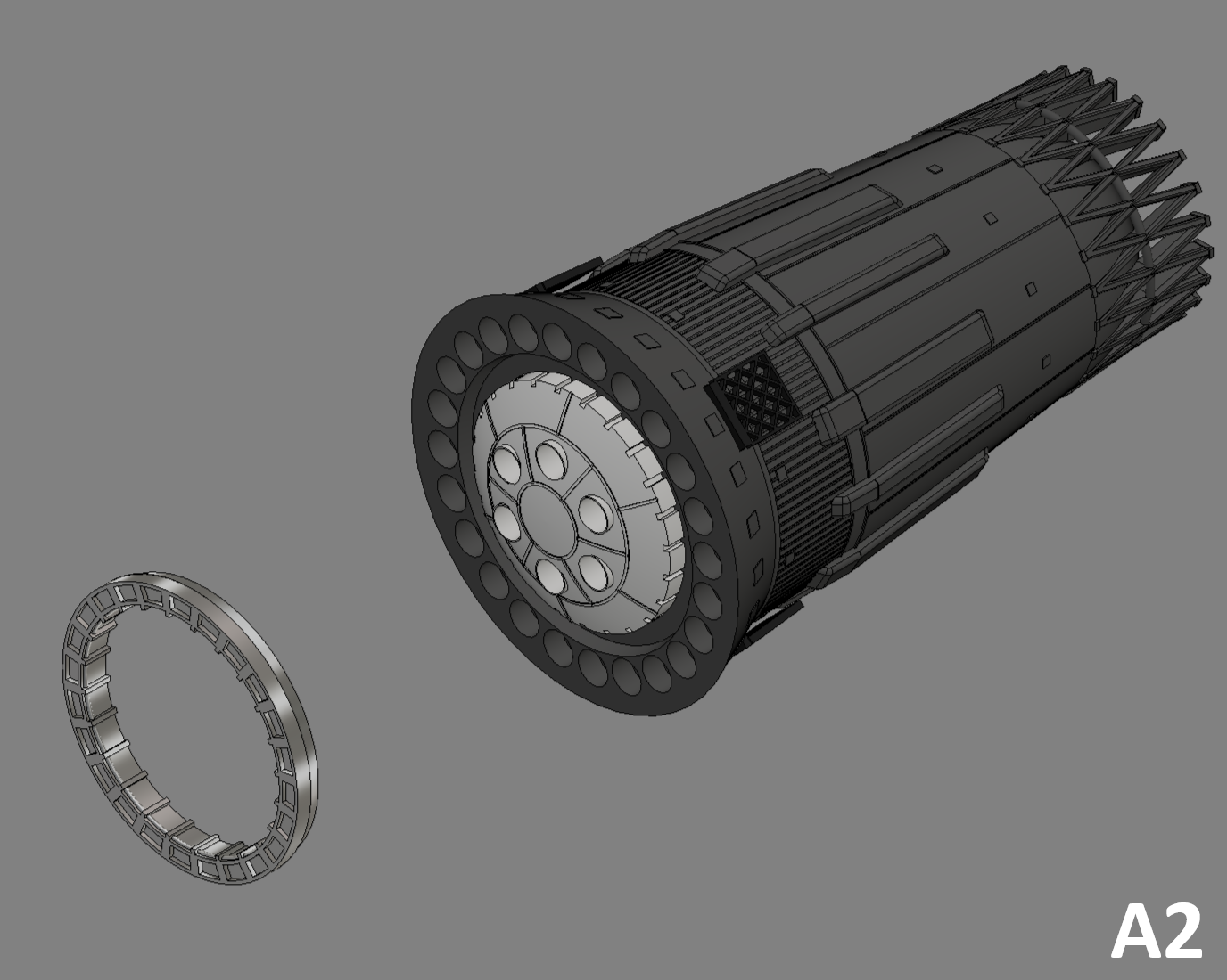
A2
- Glue "A_Engine_Ring_Metal_x1" on the bottom of "A_Tank_Grey_x1" over "A_Engine_block_White_x1".
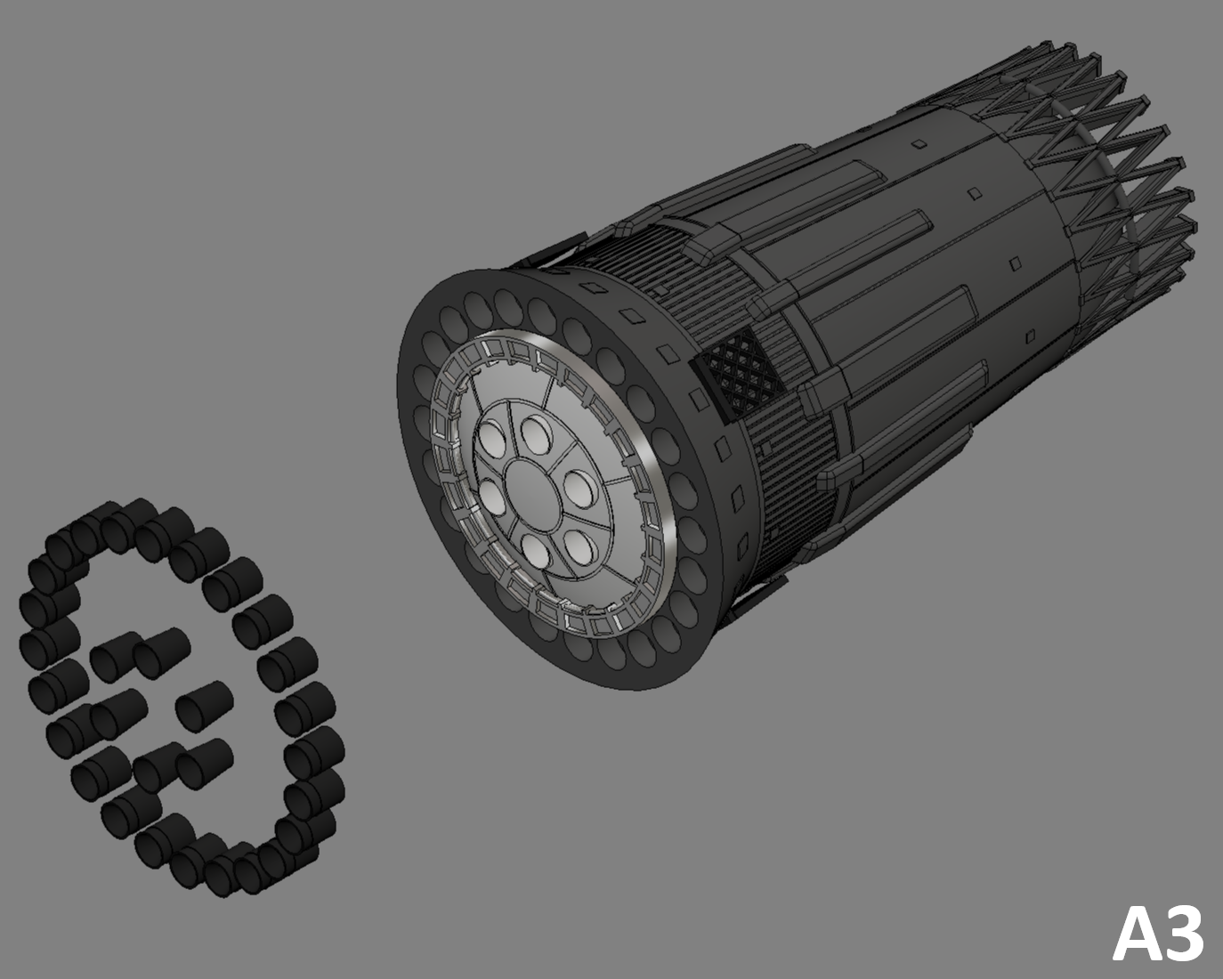
A3
- Glue "A_Engine_Ext_Black_x24" in the 24 holes provided in "A_Tank_Grey_x1".
- Then glue "A_Engine_Int_Black_x6" in the 6 holes in "A_Engine_block_White_x1".
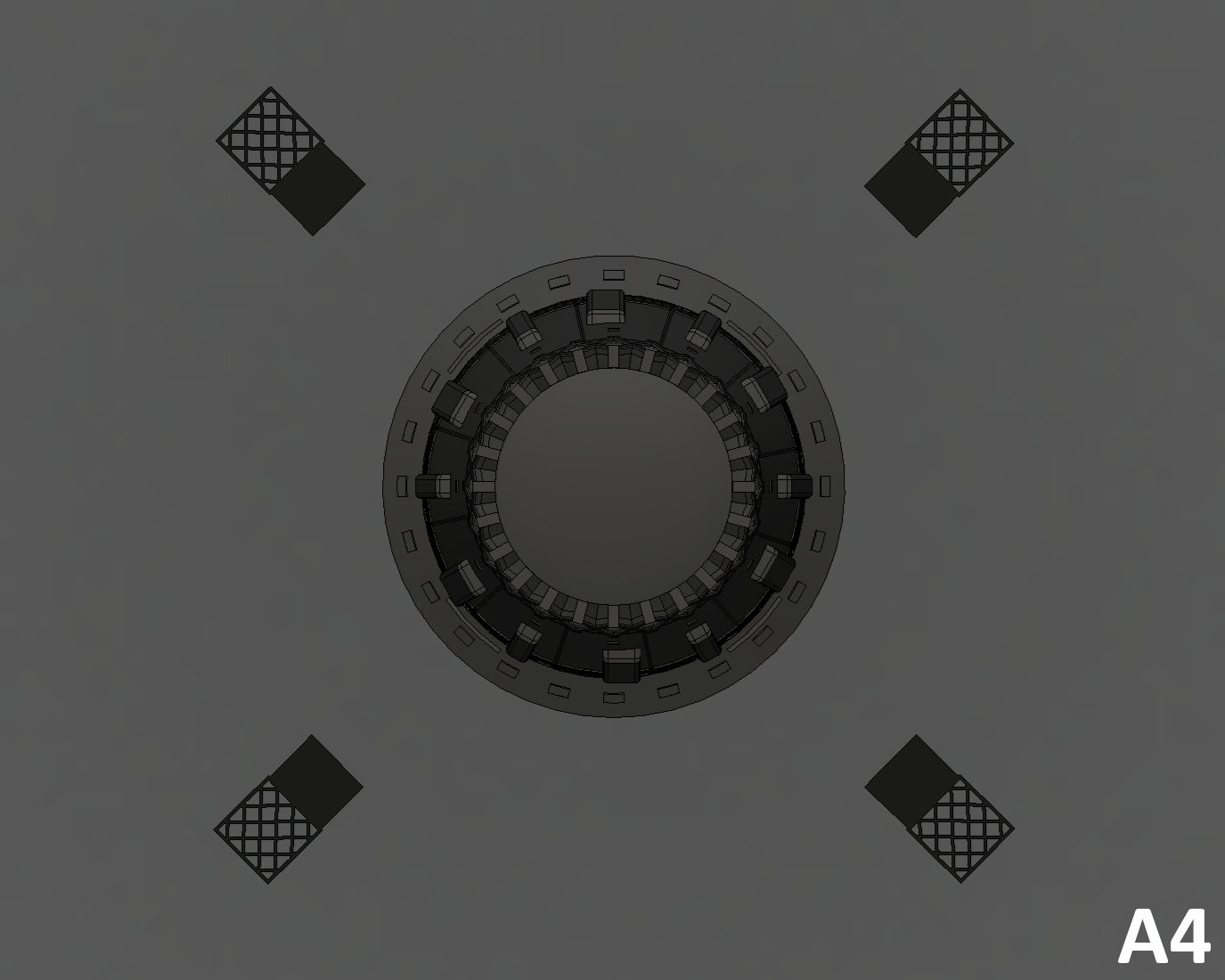
A4
- Last step, glue "A _Grid_Black_x4" into the four holes in "A_Tank_Grey_x1".
Assembly Block B
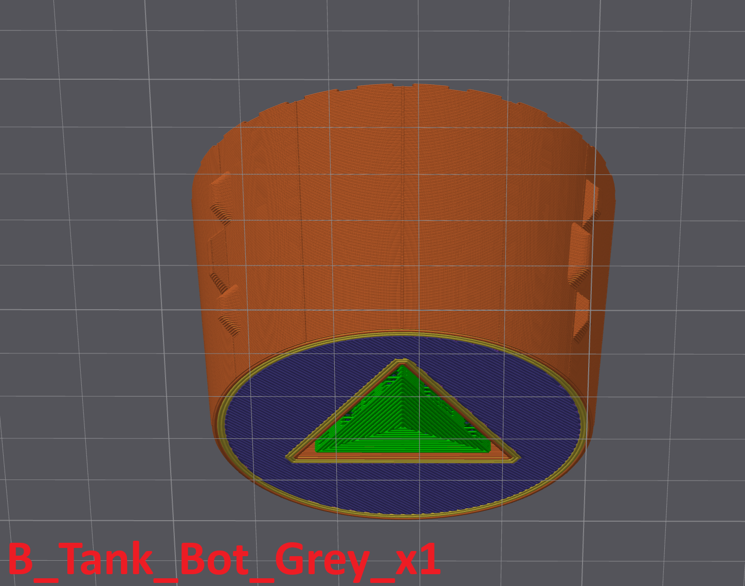
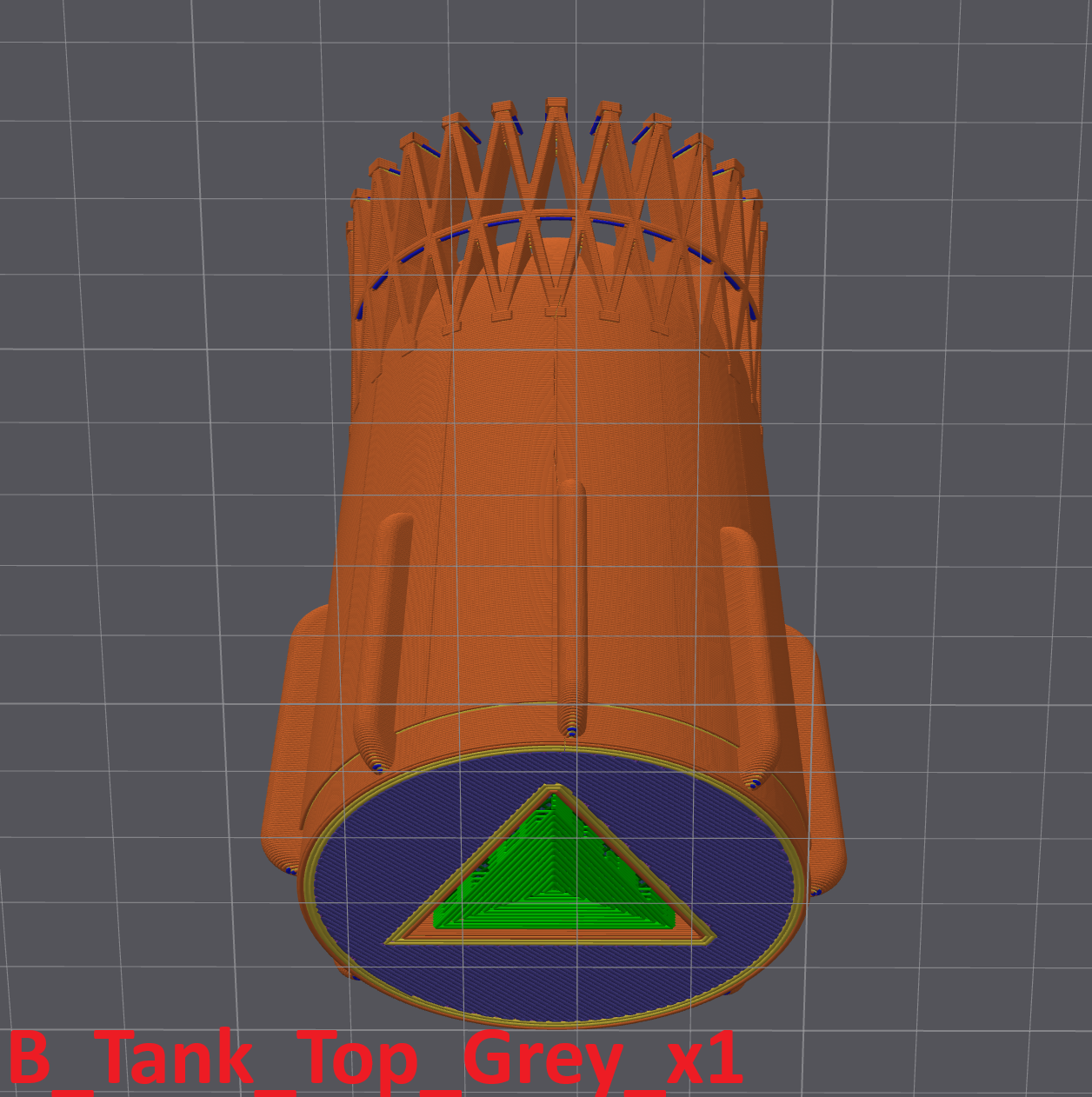
After removing the supports from the blocks, "B_Tank_Bot_Grey_x1" and "B_Tank_Top_Grey_x1" you can begin assembly.
Caution, for "B_Jonction_x1" check that the part fits with a minimum of assembly play for better alignment.
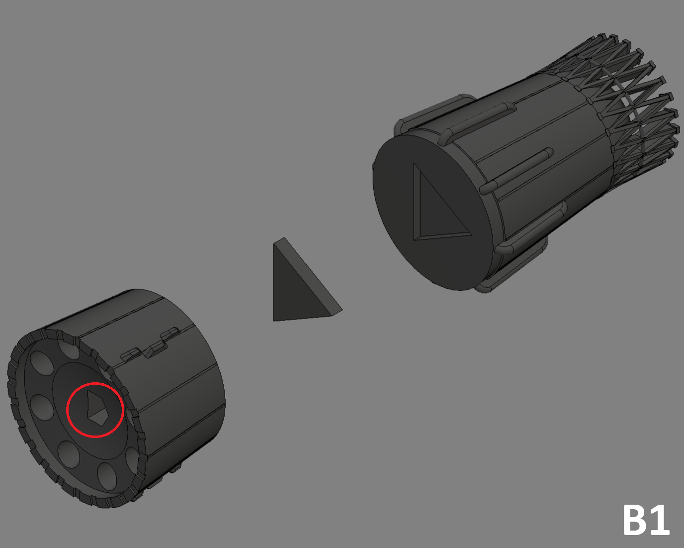
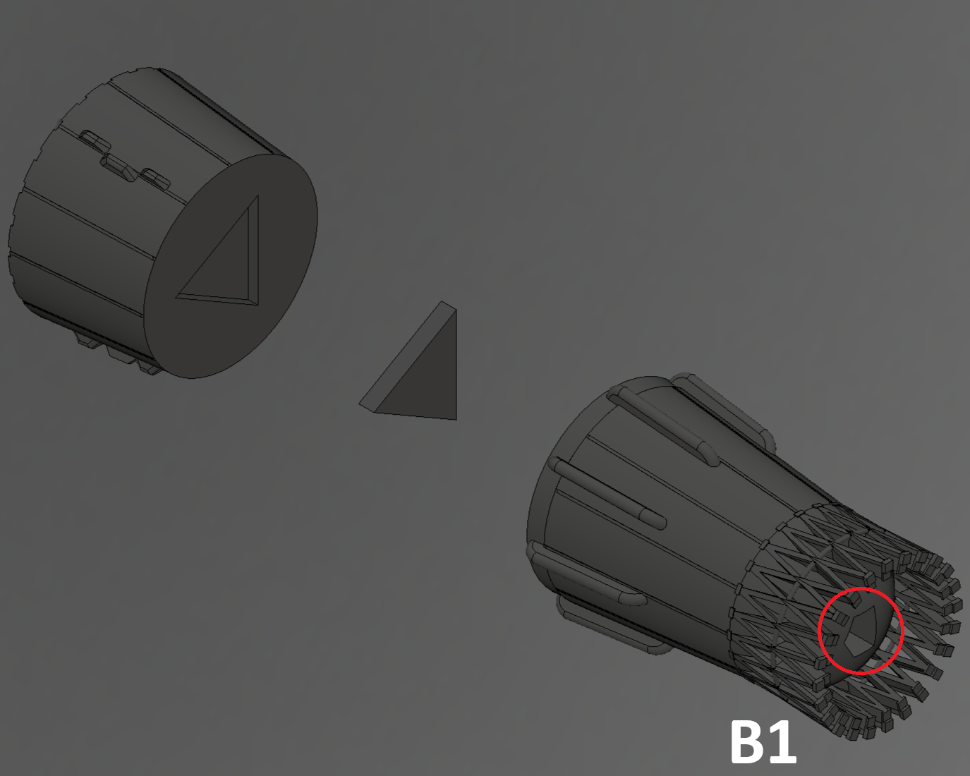
B1
- Glue "B_Jonction_x1" in "B_Tank_Bot_Grey_x1" then glue the whole in "B_Tank_Top_Grey_x1". Be careful to align the two blocks "B_Tank_Bot_Grey_x1" and "B_Tank_Top_Grey_x1". To do this, look at the shapes in the red circles.
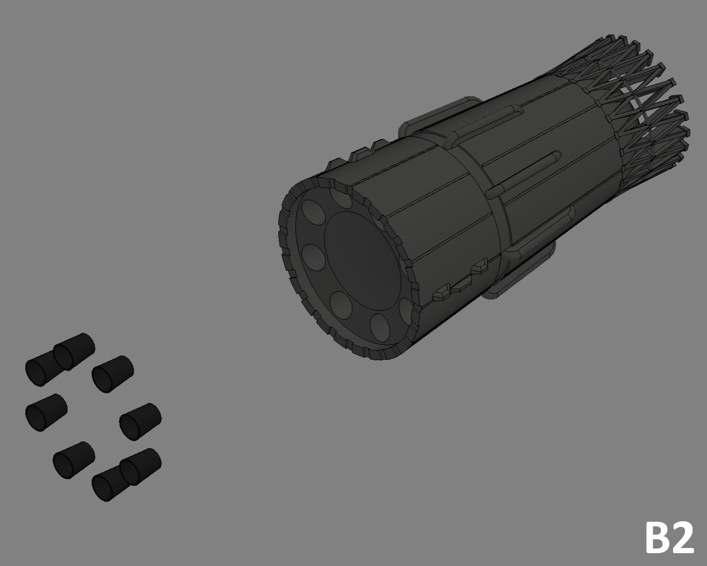
B2
- Then glue "B_Engine_Black_x8" into the 8 holes in "B_Tank_Bot_Grey_x1".
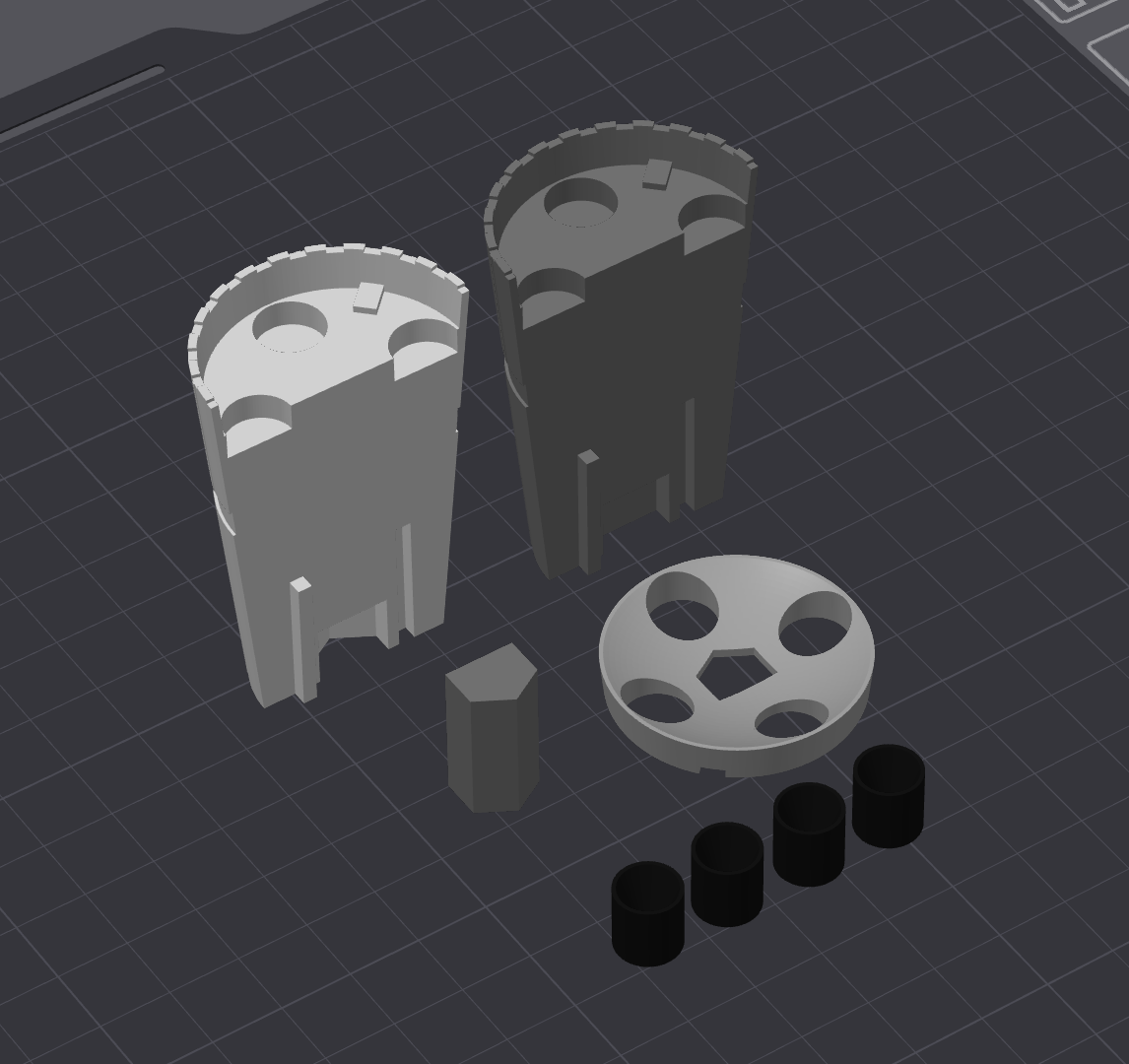
Assembly Block V
No post-printing in this block, only assembly.
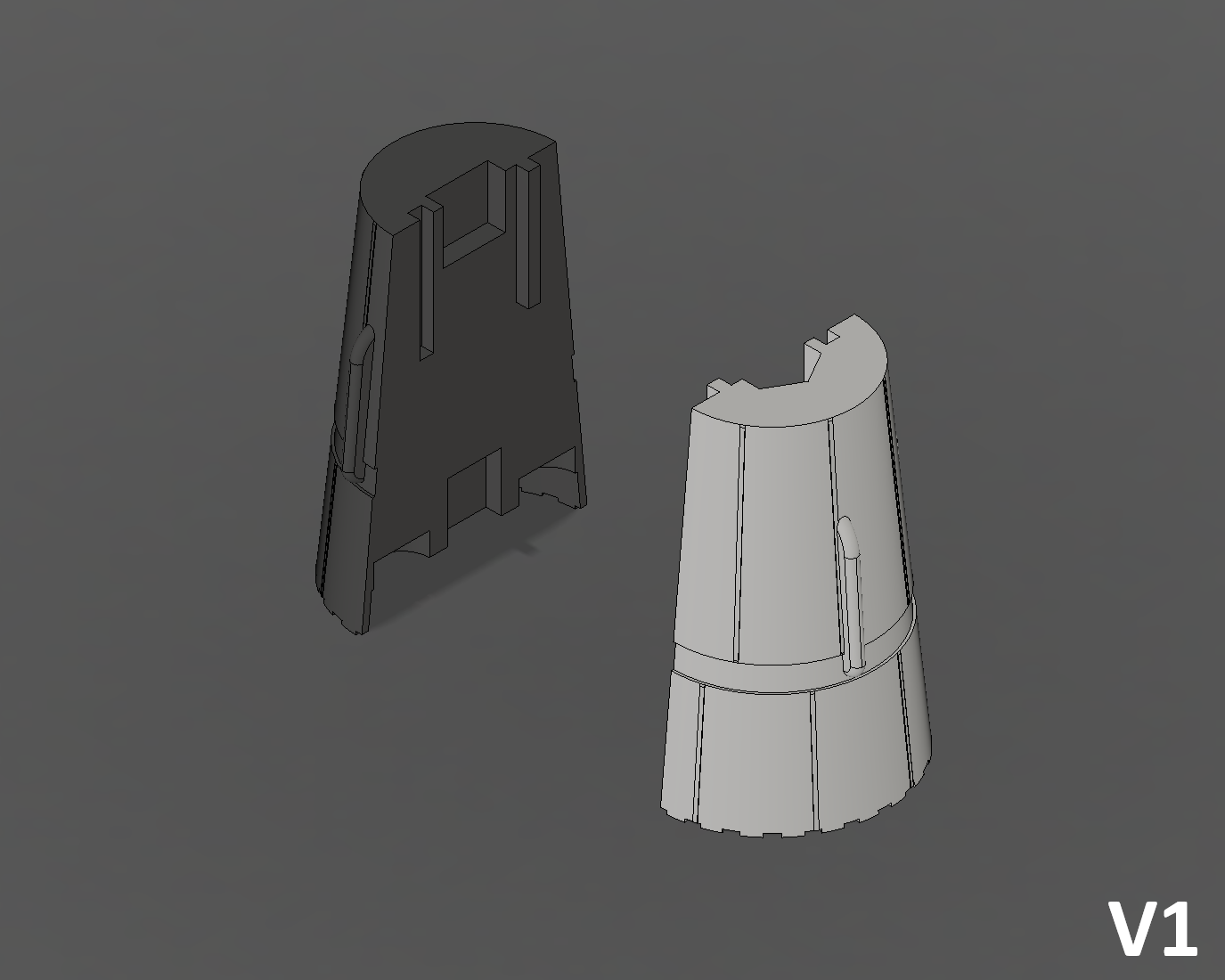
V1
- Paste "V_Tank_Grey_x1" with "V_Tank_White_x1". Make sure that both parts are at the same level.
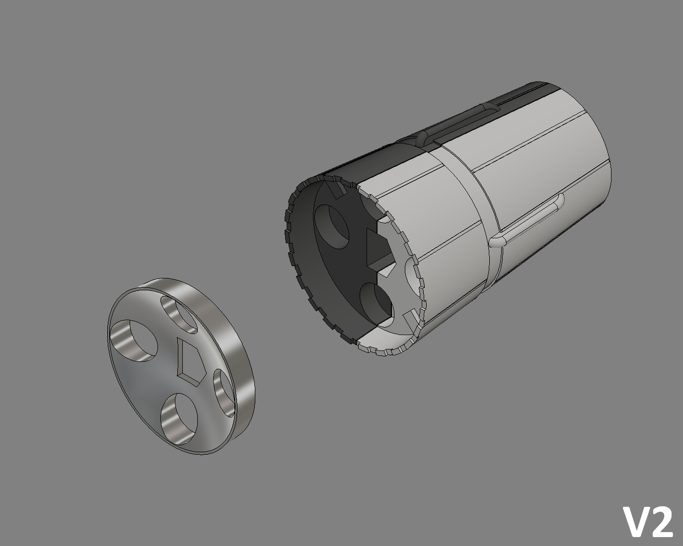
V2
- Then paste "V_Engine_Block_Metal_x1" into the V1 assembly.
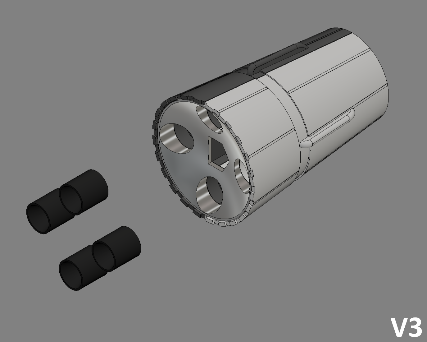
V3
- Then paste "V_Engine_Black_x4" into the V2 assembly.
Assembly Block L3
Similarly, there is no post-printing in this block, only assembly.
Depending on your choice of configuration, assembly may or may not be required.
L30
- If you've chosen the maximum height of 22 cm, you don't need any assembly, so you can go on to the next step.
L31
- If you have chosen the maximum height of 14 cm you have the parts "L3_Bot_White_x1" and "L3_Top_White_x1" to assemble with "L3_Jonction_x1".
Assembly Stand
STAND1
- Paste "N_White_x1" and "1_White_x1" to the nameplate "Name_Black_x1".
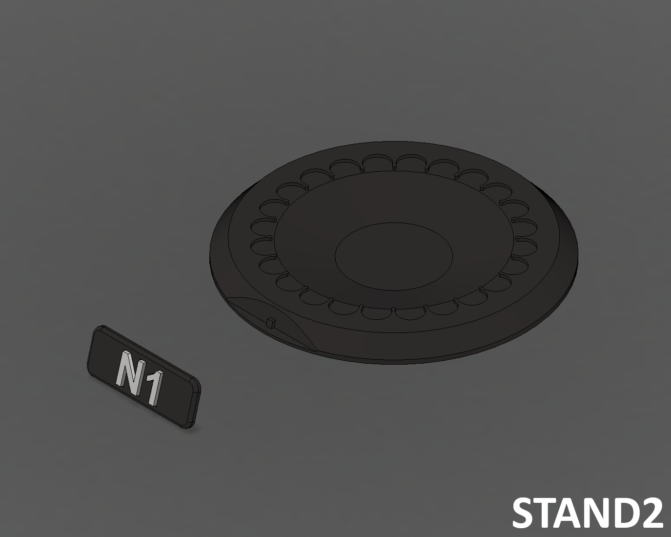
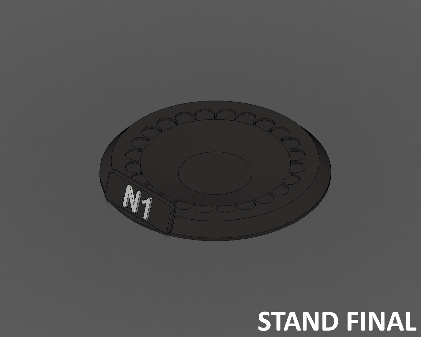
STAND2
- Paste "Name_Black_x1" to "Stand_Black_x1".
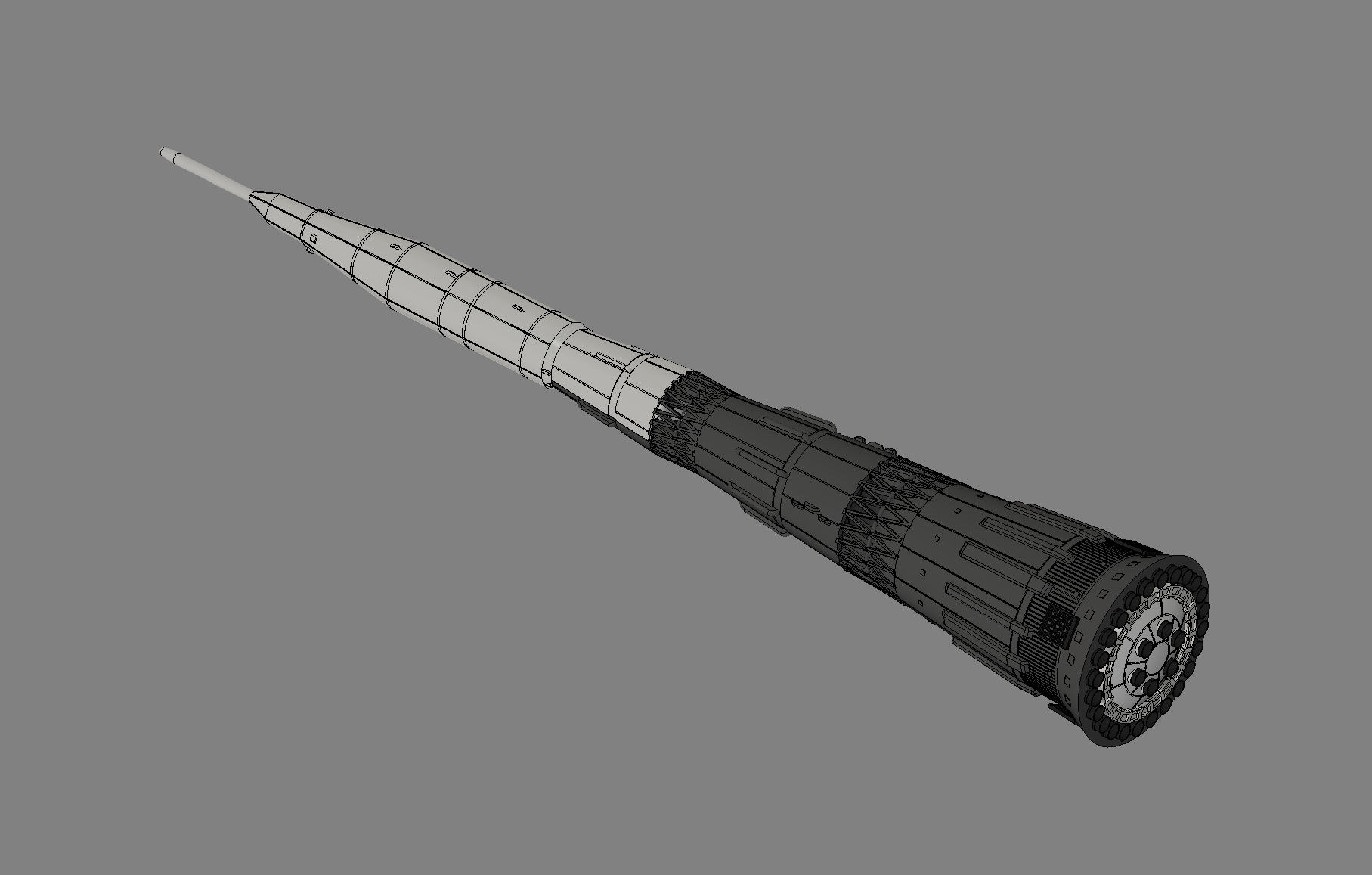
Final Assembly
Now that all the blocks are assembled, you can do the final assembly.
Glue is not required for this assembly, as it is possible to disassemble the blocks to see the engines.
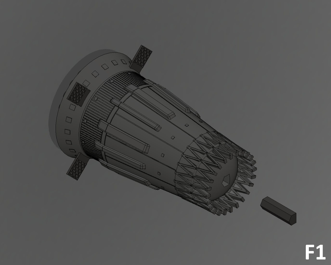
F1
- Add the "A-B_Jonction_x1" junction to "Block A".
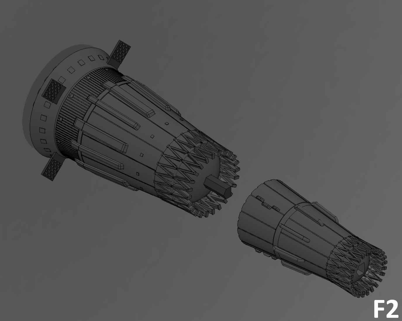
F2
- Add "Block B" to the assembly.
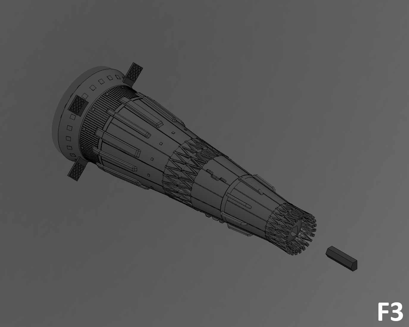
F3
- Add the "B-V_Junction_x1" junction to "Block B".
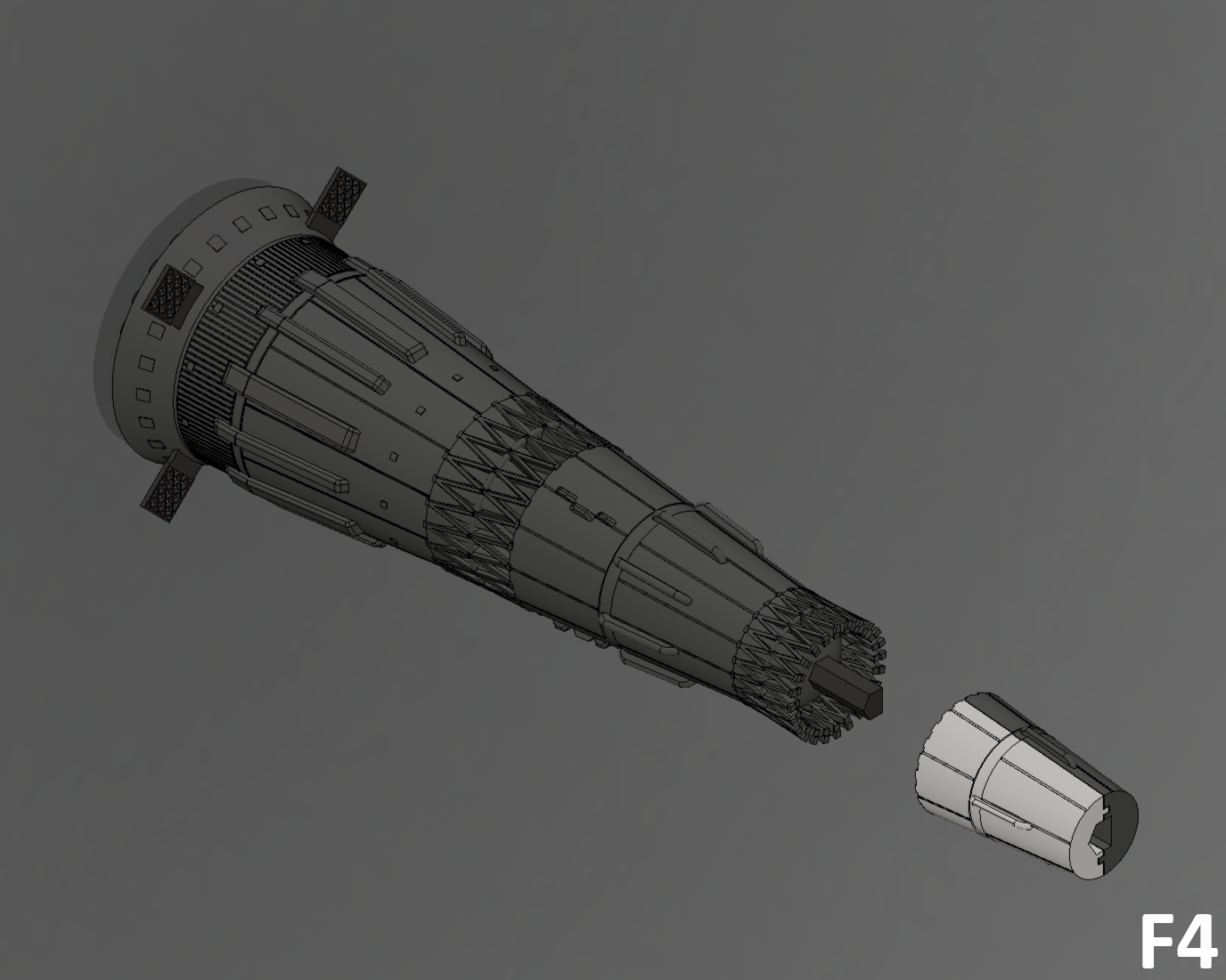
F4
- Add "Block V" to the assembly.
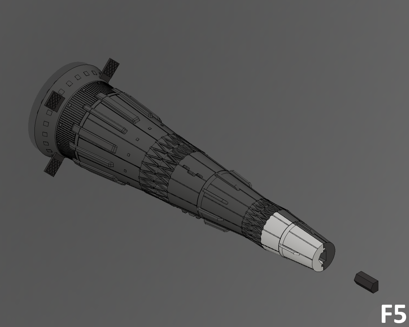
F5
- Add the "V-L3_Junction_x1" junction to "Block V".
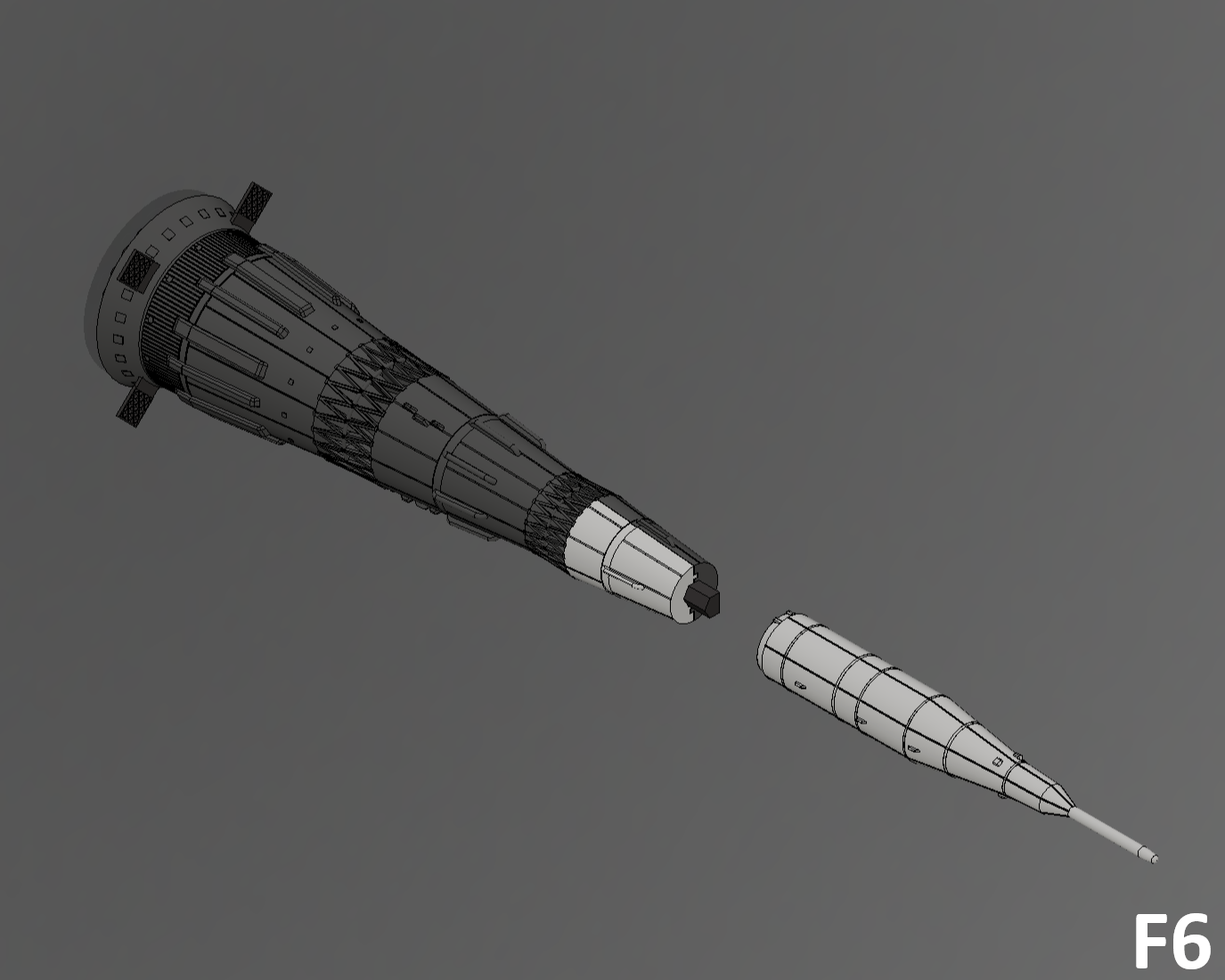
F6
- Add "Block L3" to the assembly.
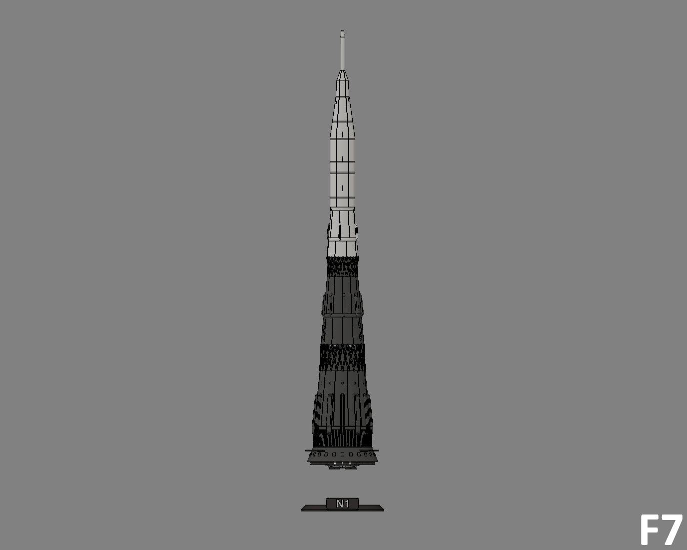
F7
- Add the assembly to the "Stand".
Finish
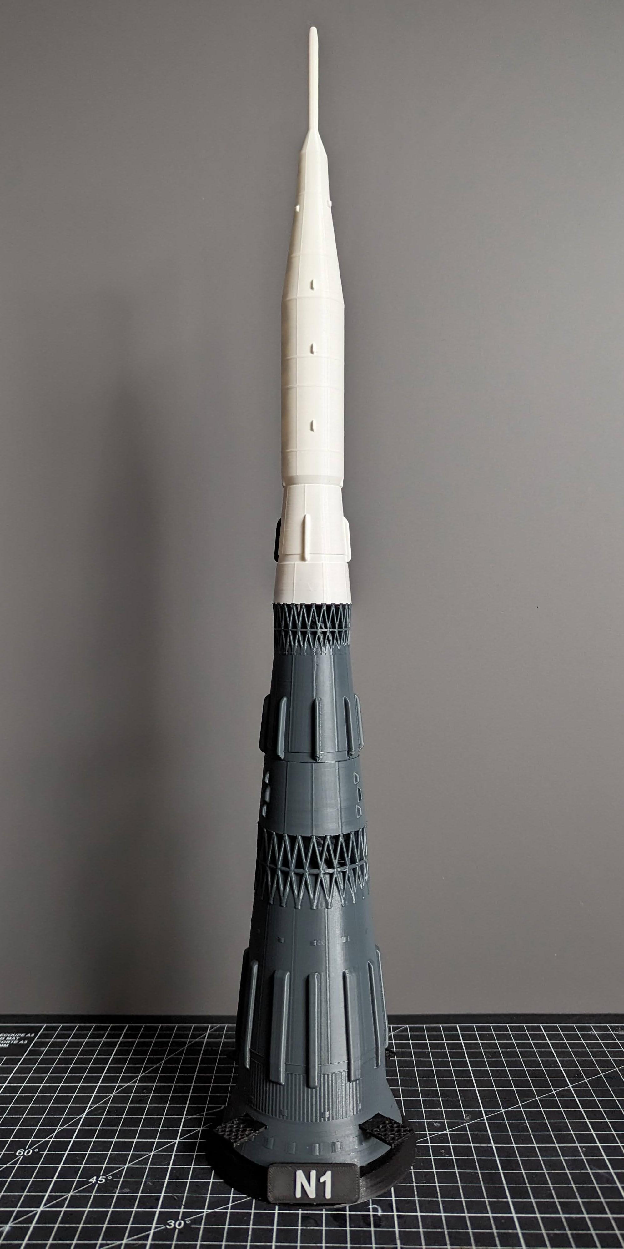
Congratulations on finishing the printing and assembly of the N1 !