Printing Conductive Patterns on Flexible Material TfCD
by erikandnadieh in Circuits > Wearables
3340 Views, 68 Favorites, 0 Comments
Printing Conductive Patterns on Flexible Material TfCD

In this instructable, we will give a basic tutorial on how to print conductive patterns on flexible materials.
What is ‘printing conductive patterns’?
A conductive pattern is a network of conductive material that conducts energy from one point to another. This is common in for example circuit boards. There are many ways to make a network like this. In this tutorial, we will explain how to print a network like this on a flexible material.
Why printing conductive patterns?
When prototyping an interactive product, we often use a microcontroller connected to various different elements. To connect these elements, we usually make the first prototype on a so-called breadboard. But, these bread boards are quite large and often not possible for use in a fully functional prototype. The traditional way is to transfer the circuit to a printed circuit board (PCB), often made through etching or milling. But what if you could just print out the circuit board directly, in an ordinary tabletop printer? This is where the technology we will be using comes in handy. In addition it also makes flexible products and is fast, maybe (at least in a future perspective) fast enough to even replace the breadboard.
How does it work?
Printing conductive patterns works in the same way as printing other 2D print products. Only, the paper and the ink differs from regular print products. The printer will print an A4, and make all the black parts of conductive material, or conductive ink we should say – which includes silver particles to make it conductive. When the conductive pattern has been printed, all other elements like LEDs and resistors can be taped or glued, using conductive special tape or glue (also including silver) on the conductive patterns. Soldering, as is commonly used on ordinary PCBs, are not recommended, as it will destroy the paper we have printed on.
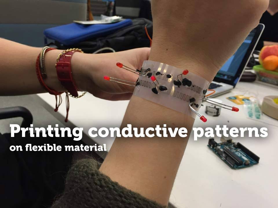
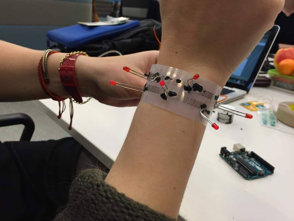
What are we making?
To show the advantages for prototyping with printed conductive pattern, we will make a Christmas bracelet! The bracelet has six LEDs in two series, that blink separate from each other.
What do you need?
- Printer. You can use Brother printers that use LC71 (Americas), LC1240 (Europe) or LC12 (Japan) cartridges.
- AgIC cartridges.
- Paper. For the paper, you can use any printable transparent paper.
- Arduino Uno
- Any computer
- A number of LED’s
- Connecting wires
- Conductive tape or glue
Installing Conductive Ink Cartridges
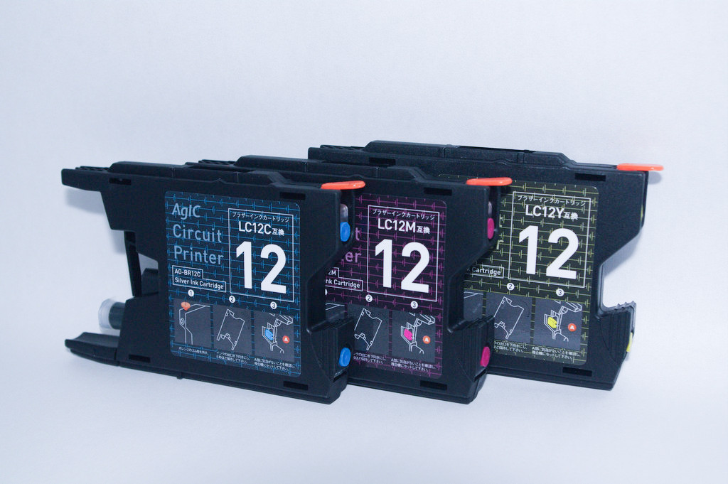
You can use your normal inkjet printer to print the conductive patterns, but you do have to install the conductive ink cartridges, which are only available to selected printer models.
The cartridges we used were from ‘AgIC’, they produce cartridges for normal inkjet printers. They made very clear instructions on this part, so please visit https://drive.google.com/file/d/0B9Zc_nXv1uGPWE5JX3ZyTG9tdFU/view?pli=1
Computer Settings and Software
For the cartrigdes, AgIC also have recommendations regarding the printer settings. These could be found here:
Mac: https://drive.google.com/file/d/0B9Zc_nXv1uGPWE5J...
Windows: https://drive.google.com/file/d/0B9Zc_nXv1uGPWE5J...
Also, download the Arduino software to be able to write the program to the microcontroller. Last, but not least, you need a software to do the circuits. We are using CadSoft Eagle, which is free to download, but if you have the experience with another program that you prefer, you could equally well use that. The only important thing is that you end up with a printable A4 (max) size file, where the conductive pattern is black on a white background.
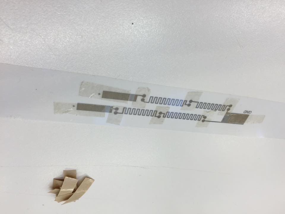
Draw the Circuit
Draw the desired network for printing. In this step we use CadSoft Eagle, to first draw a schematic circuit. Use the add button to add components, and the net tool to connect them. We have two +5V sources (from the Arduino), six LEDs and one ground. Transfer the schematic to a board layout by using the button in the top left. In this stage you could use the autoroute option (make sure to have it selected to only route on one side), but we’d recommend you to draw them manually, adding meanders to the routes to slightly reduce the risk of breaking. Additionally we have added square pads for ground and the two +5V sources. Make sure you still only do everything on one side of the board. You could also make the standard size of the pads and routes bigger, using the Design Rules menu found under ”Edit”. Before printing (or exporting to pdf), make sure that only the layer you have been drawing on, as well as the ”pads” layer are selected in the layer settings menu found in the top left corner of the toolbox.
On printing (or exporting to pdf) make sure to select ”black and white” as your printing option. If you chose to export it to a pdf file, you could also do some finishing touches in for example Adobe Illustrator. We opted for example to multiply the path (to make several prototypes) and to fill out the holes in the pads.
In the end, all the black parts of the drawing will be printed as conductive parts. If you are new to programming and Arduino, we would still advise you to first make a prototype of your circuit with a breadboard, to make sure your circuit works.
Download the file 'Board.pdf' if you want to copy our circuit.
Downloads
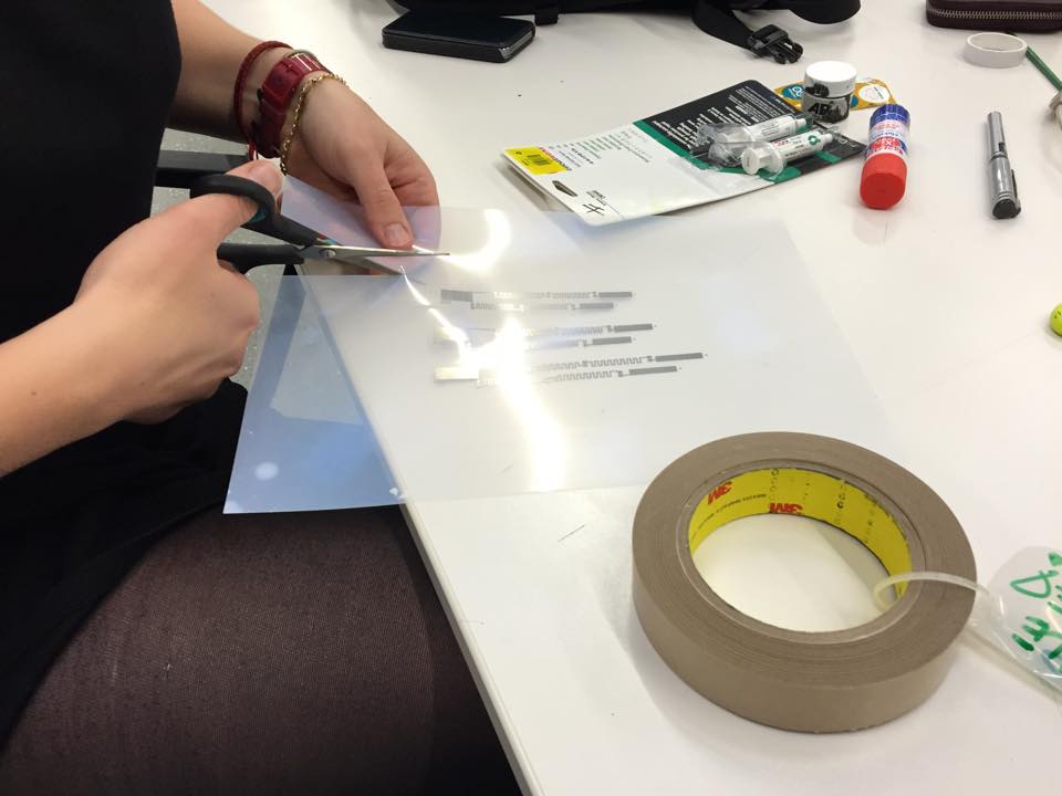
Print the Circuit
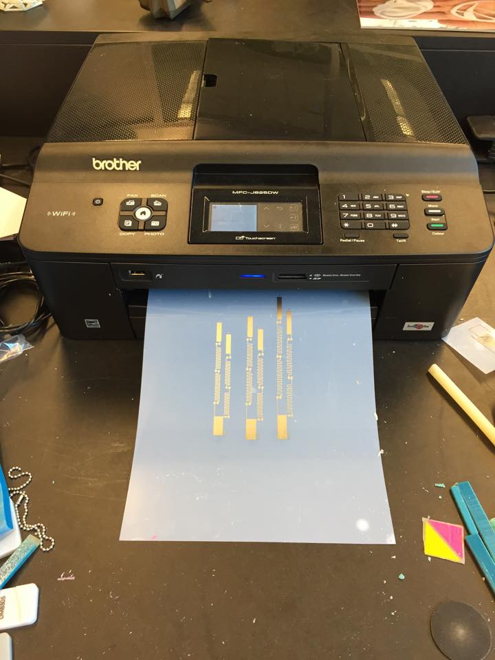
Print the conductive patterns. Make sure your printer settings are correct, see step 2.
Write the Arduino Program
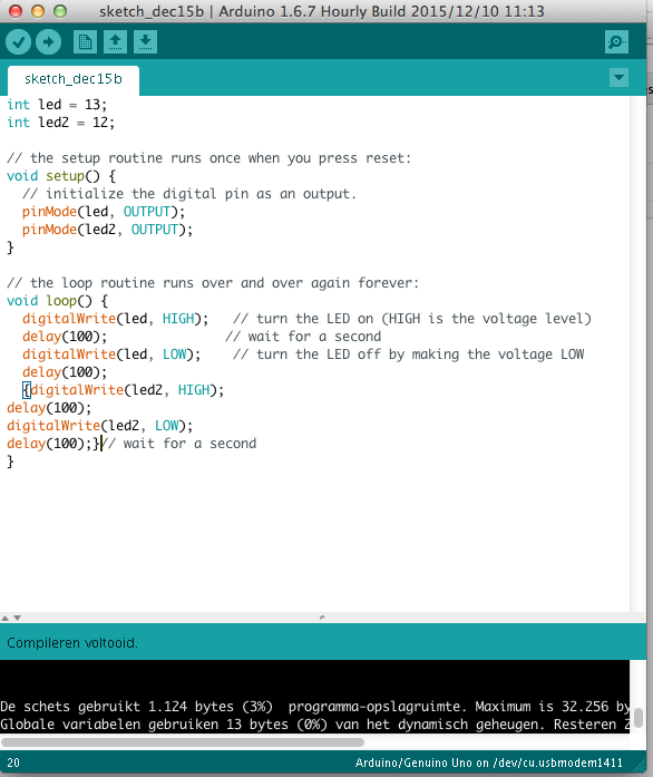
You can write your own, or copy the program we used for this instructable. The program we used makes two sets of LED’s blink separate from each other. Verify and upload your program to the microcontroller. Again, we advise you to first make this circuit work on a breadboard, before connecting the elements to the printed circuit. Even if using tape, making the components reusable, the connectivity gets worn down quite quickly.
If you want to use the same program, copy the following to your Arduino file:
int led = 13;
int led2 = 12;
// the setup routine runs once when you press reset:
void setup() { // initialize the digital pin as an output.
pinMode(led, OUTPUT);
pinMode(led2, OUTPUT); }
// the loop routine runs over and over again forever:
void loop()
{ digitalWrite(led, HIGH); // turn the LED on (HIGH is the voltage level)
delay(100); // wait for a second
digitalWrite(led, LOW); // turn the LED off by making the voltage LOW
delay(100);
{digitalWrite(led2, HIGH);
delay(100);
digitalWrite(led2, LOW);
delay(100);}// wait for a second }
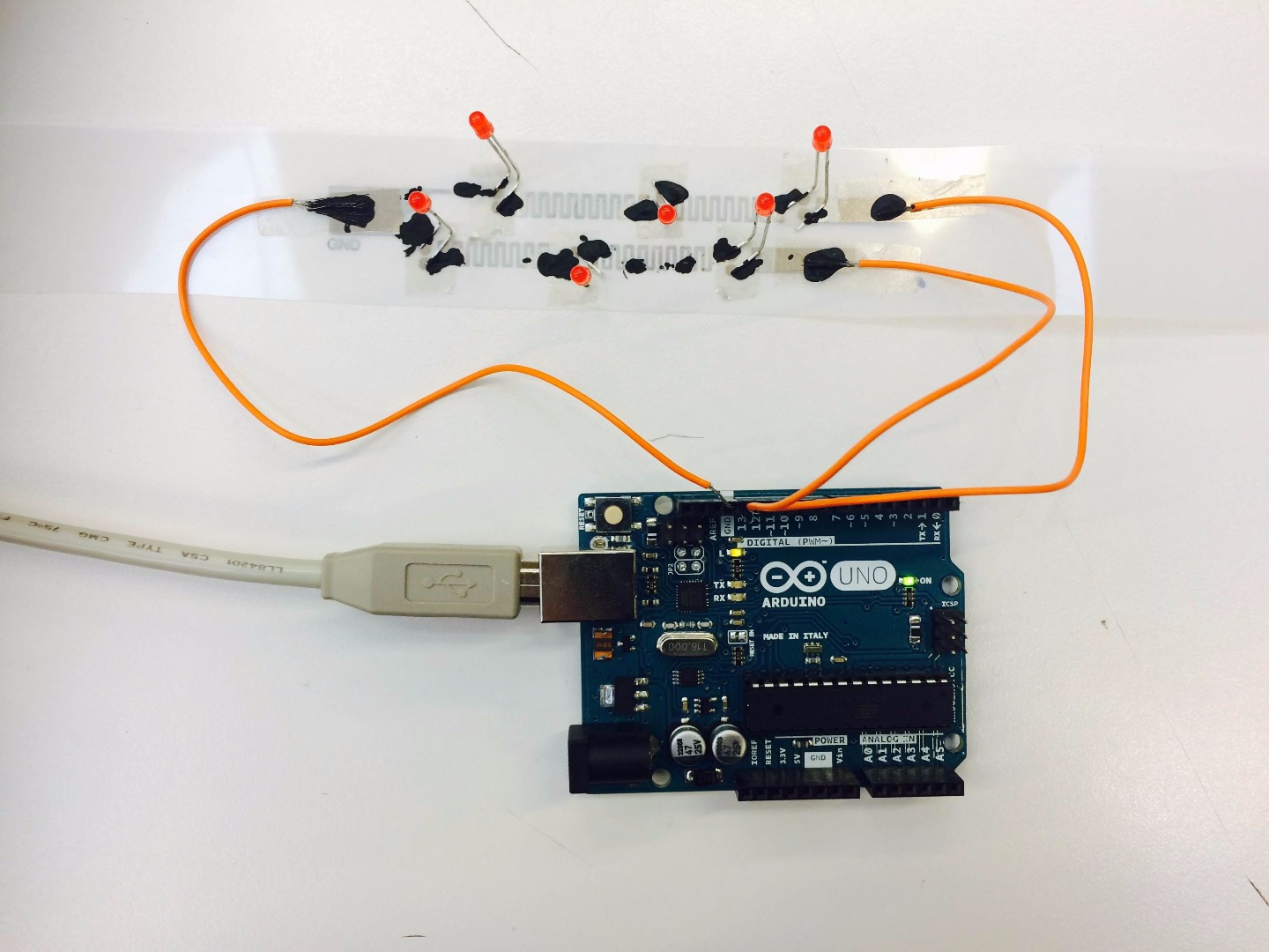
Connect the Elements
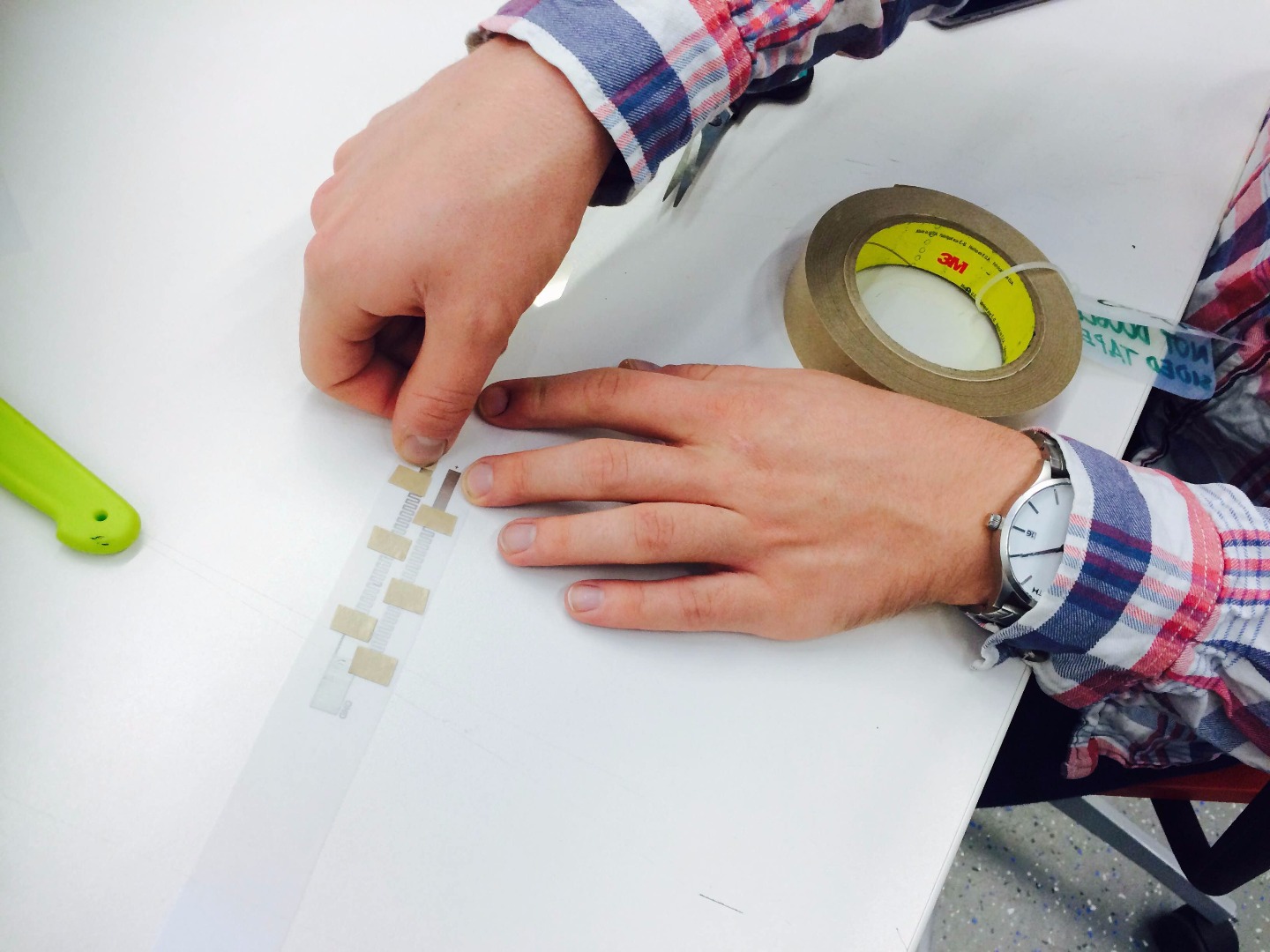
Connect the elements (LEDs) to the printed circuit. We used conductive tape (http://nl.rs-online.com/web/p/conductive-adhesives/0496265/), but it is also a possibility to use conductive glue (http://nl.rs-online.com/web/p/conductive-adhesives/2209928/), or to make your own conductive glue (https://www.instructables.com/id/Make-Conductive-Glue-and-Glue-a-Circuit/). We used the home-made conductive glue additionally to the tape.
The tape only conducts in the Z-direction, so make sure the elements are placed on top of the printed parts where you need to connect them. Connecting the LED’s: Make sure the long pins of the LED are connected to the plus side of the circuit. Connecting the wires: connect the ground to the ground, and the input wires to input 12 and 13.
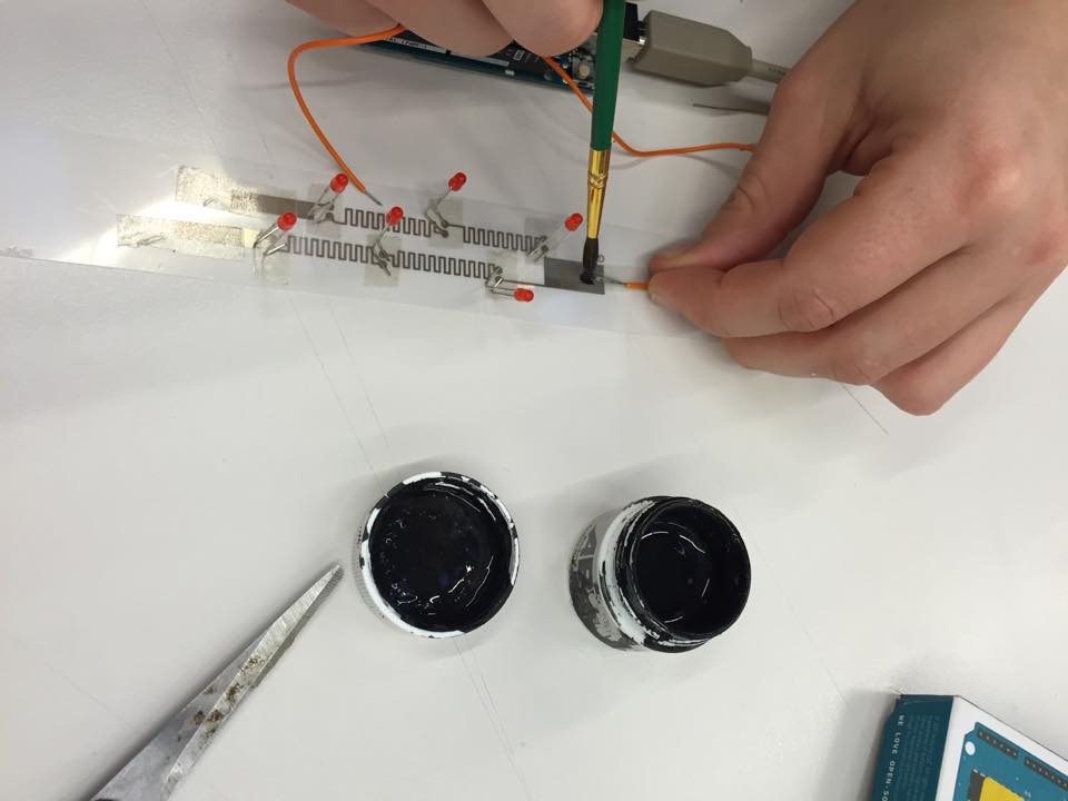
Get the Circuit Working!
.JPG)
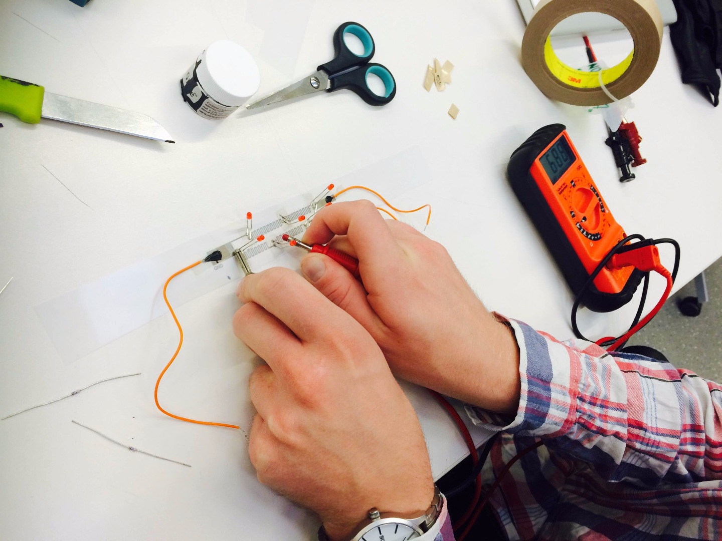
To check if the circuit was conductive, we used a voltage meter. This is optional. When you have uploaded the Arduino program, the circuit should work. However, it may occur that the resistance in the circuit is to high due to the resistance in the connections and the internal resistance in the circuit (it happened to us). You can minimize the resistance by putting on extra glue, but there is a possibility that 5V (the power from the Arduino) isn’t enough to get your circuit working. Then we suggest to get an external power source and increase the voltage until the LED’s start working and/or to connect the Arduino to an H-bridge.
Have fun!