Potentiometer Feedback Control: Implementing a Soft Extend Limit
by Progressive Automations in Circuits > Arduino
8387 Views, 58 Favorites, 0 Comments
Potentiometer Feedback Control: Implementing a Soft Extend Limit

In this Instructable we will be debriefing the method of setting a soft extension limit for actuators with potentiometer feedback. After completing this tutorial you will be able to successfully control the fully extended position of a linear actuator. All programming will be completed in the Arduino IDE.
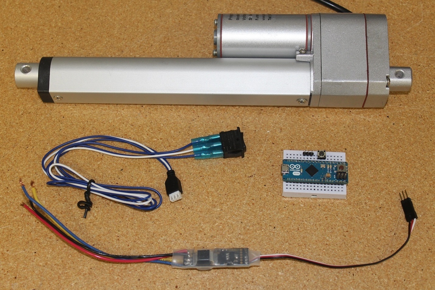
For this tutorial we will be using the following components:
1 x Arduino Micro
1 x Momentary 3-Position Rocker Switch
1 x Tactile Pushbutton
1 x Small Breadboard
1 x Power Supply
Before we get started, please note the following risks and limitations risks associated with setting a soft limit:
1. The saved extended limit is reset to the original full extension limit once the Arduino loses power/reset.
2. This system should not be used in applications where human life or health or significant property value depend on its proper operation.
3. Please note that Progressive Automations is not responsible for user caused error due to improper handling of electric components.
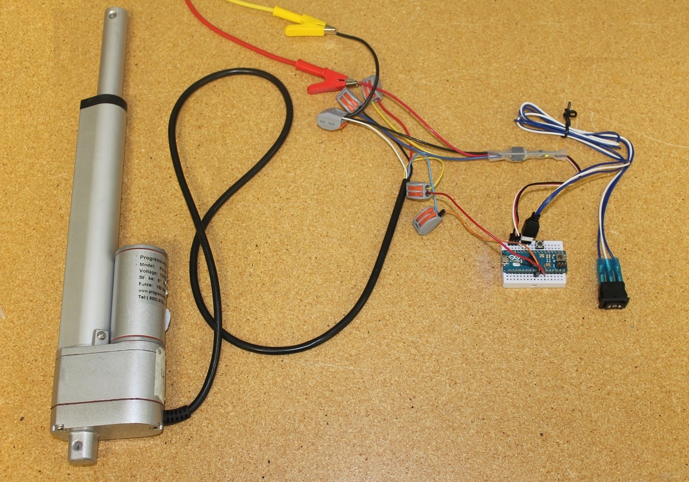
Hardware Setup


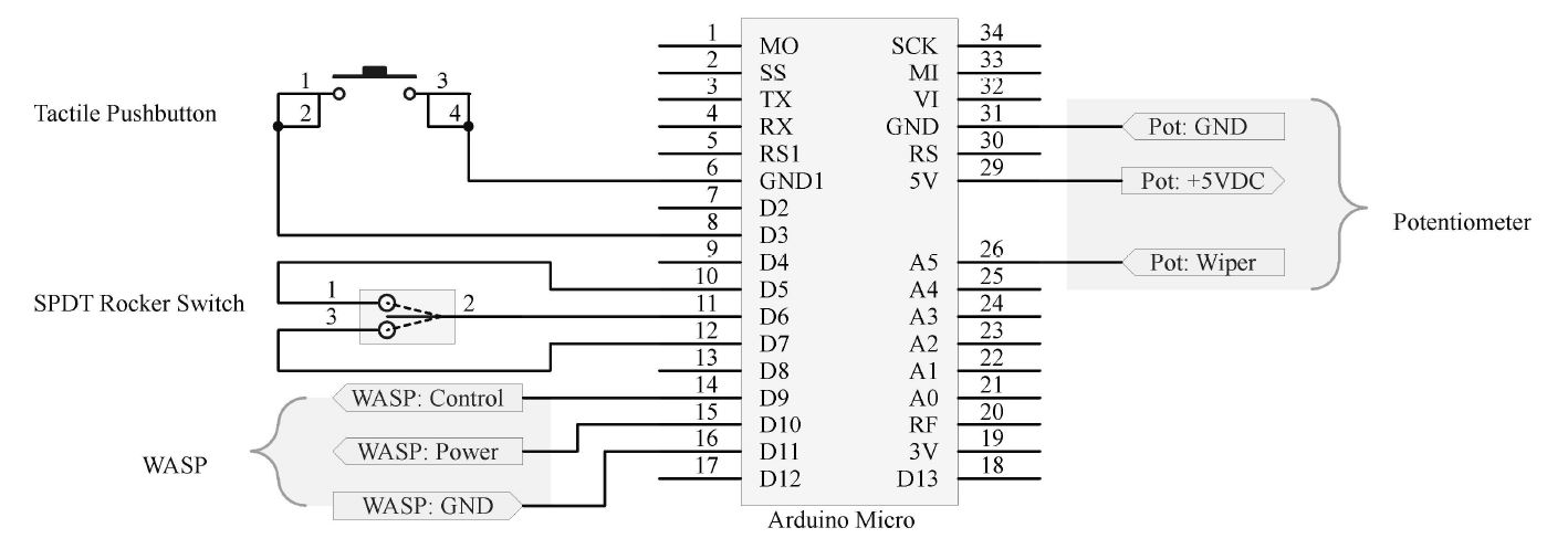
Connection of the hardware will depend on the choice of the input/output pins that the programmer decides to use. In our scenario, we will be using the digital and analog pins as noted in Schematic 1.
The WASP requires a servo signal for operation. The Arduino Micro has one servo control pin, which is located on IO pin 9.
IO on the Arduino:
- Potentiometer
A5 = Pot: Wiper (Blue)
5V = Pot: +5VDC (Yellow)
GND = Pot: GND (White)
- WASP
D9 = WASP: Control (White)
D10 = WASP: Power (Red)
D11 = WASP: GND (Black)
- Rocker Switch
D5 = Pin 1 (Blue)
D6 = Pin 2 (White)
D7 = Pin 3 (Blue)
- Pushbutton
D3 = Pins {1,2}
GND1 = Pins {3,4}
- On-board LED
D13 = Leave disconnected. Indicator light for control
Software Setup
Now that the IO pins are selected, software configuration can begin. The first step is to define constants and declare global variables. Since we are using a servo function, we need to include the servo header.
#include <Servo.h>              //Servo Header
Servo myservo;                  //Servo Object

define POT A5               	//Potentiometer Wiper Feedback

#define EXTEND 7                //Extend via Rocker Switch

#define RETRACT 5            //Retract via Rocker Switch
#define RS_GND 6             //Rocker switch ground
#define SAVE  3              //Pushbutton to save extended limit

#define WSP_CNTRL  9          //WASP Control
#define WSP_ENABLE 10         //WASP Enable
#define WSP_GND   11          //WASP Ground

#define LED 13                //On-Board LED

#define BACKWARDS 1000        //Servo value to retract actuator
#define FORWARDS  2000        //Servo value to extend actuator
#define MTR_STOP  1520        //Servo value to stop actuator

#define HOLD_TIME 3000        //Save Button Hold Time

// Inputs //
bool rsExtend = false;        //Rocker Switch  - Extend Deactive
bool rsRetract = false;       //Rocker Switch  - Retract Deactive
bool pbSave = false;          //Push Button - Save Deactive

// Analog Initialization //
int potValue = 0;             //Potentiometer analog value init
int strokeLimit = 1023;       //Set stroke limit to max analog value

// Global Flags //
bool saveFlag = false;        //Pushbutton save flag
int extendLimit = 1023;       //Extension limit, max value
bool limitFlag = false;       //Clear limit Flag
bool ledState = false;        //LED Off

// State Machine //
int currentState = 1;         //State machine init
int mtrState = 1520;          //Motor Stop init

// Debounce Function //
int buttonState;              //Current reading from the input pin
int lastButtonState = LOW;    //Previous reading from the input pin
long lastDebounceTime = 0;    //Last time the output pin was toggled
long previousMillis = 0;      //Stores how long button is pressed
long debounceDelay = 3000;    //Debounce time, 3s

// Smooth Routine //
const int numReadings = 10;   //Number of readings
int readings[numReadings];    //Readings from the analog input
int readIndex = 0;            //Index of the current reading
int total = 0;                //Running total
int average = 0;              //Average
The declarations and constants include much more than just the hardware initialization. As we can see, we are initializing all variables that will be used within our program. There are a total of 8 functions within our code:
- 2 Standard Functions:
Setup() = Hardware and Software Initialization
Loop() = Main code, including all custom functions
- 6 Custom Functions:
inputScan() = Reads the real world values
flagFunc() = Handles flag events
stateSelect() = State Machine
writeOutput() = Writes to real world devices
potFeedback() = Potentiometer read smooth and constrain function
strokeSave() = Extension limit save procedure
Each function will be discussed further in this tutorial. Here is the setup initialization as well as the main loop that runs continuously:
//// Initialization Procedure ////

void setup() {
  myservo.attach(WSP_CNTRL);  //WASP Servo Pin 9 Init C

  pinMode(POT, INPUT), digitalWrite(POT, LOW); //Potentiometer init

  pinMode(EXTEND, INPUT), digitalWrite(EXTEND, HIGH);	//RS Extend Init A
  pinMode(RETRACT, INPUT), digitalWrite(RETRACT, HIGH); //RS Retract Init B
  pinMode(RS_GND, OUTPUT), digitalWrite(RS_GND, LOW);   //RS GND Init C

  pinMode(SAVE, INPUT), digitalWrite(SAVE, HIGH);       //Save PB Init

  pinMode(LED, OUTPUT), digitalWrite(LED, LOW);         //On-Board LED Init

  pinMode(WSP_ENABLE, OUTPUT), digitalWrite(WSP_ENABLE, HIGH);     //WASP Init A
  pinMode(WSP_GND, OUTPUT), digitalWrite(WSP_GND, LOW); 	   //WASP Init B

//Smooth Routine Init //

  for (int thisReading = 0; thisReading < numReadings; thisReading++) {
    readings[thisReading] = 0;

  Serial.begin(9600); 	//Serial Communication Init
}

//// Main Loop ////

void loop() {
  inputScan(); 	        //Read Inputs
  stateSelect(); 	//State Machine
  flagFunc(); 	        //Global Flag Routine
  writeOutput(); 	//Set Outputs
}
Reading Analog and Digital Inputs
A simple input scan function, as seen embedded in the main loop, consists of reading the rocker switch signals, the potentiometer feedback and the pushbutton responsible for saving the extended stroke limit.
// Input Read Function //
void inputScan() {
  rsExtend = digitalRead(EXTEND); //Check EXTEND (pin 5) to see if low
  rsRetract = digitalRead(RETRACT); //Check RETRACT (pin 6) to see if low
  potFeedback(); //Check potentiometer value
  strokeSave(); //Check to see if the stroke save pushbutton is active
}
We set the rocker switch and the push button active low. This ensures that the button is truly being activated.
Flag Function
In order to trigger a save function we will be using flags. We determine if the potentiometer value is equal to or greater than the selected stroke extension value. If so, the limit flag is activated. To prevent program error, we state that if the extend button is pressed on the actuator, the limit flag is false. The logic that prevents the actuator from extending occurs in the state machine function which will be further discussed in the article.
// Flag Event Function //
void flagFunc() {
  if (potValue >= extendLimit) //Determine if the potentiometer value is at the user set extended limit
    limitFlag = true;
  Serial.print("LimitFlag: "), Serial.print(limitFlag), Serial.print("\t\t");
  if (rsExtend == false) limitFlag = false; //Limit flag clear
}
Potentiometer Feedback
The precision of setting the extended limit relies on potentiometer feedback. The Arduino continuously reads an analog value from 0 to 1023 which is proportional to the actuators position. The code will compare the real value of the pot to the saved extended pot value to determine if the limit is met. An important aspect to consider is the jumpiness of real world analog signals. Adding a constraining and smoothing routine to the code will ensure that the value being read by the Arduino is the true real world value.
This routine will be embedded in the input scan function. We can see that the final potValue is the running average from the previous number of readings – in our code we take the average from the previous 10 readings
With this code, we are able to acquire an analog reading accuracy to a degree of 1 bit. This value translates to a 0.05mm precision of repeatability when using this code on a PA-14P mini-linear actuator..
//// Potentiometer Read Smooth and Constrain Function ////
void potFeedback() {

potValue = analogRead(POT);              //Read potentiometer analog value
potValue = constrain(potValue, 0, 1023); //Limit pot value

total = total - readings[readIndex];     //Subtract the last reading
readings[readIndex] = potValue;          //Read the current potValue

total = total + readings[readIndex];     //Add the reading to the total
readIndex = readIndex + 1;               //Next position in Array

if (readIndex >= numReadings) {          //If we're at the end of the array
  readIndex = 0;                         //Reset the index
}

// calculate the average:
average = total / numReadings;          //Average calculation
potValue = average;         //Set the potValue to the average calculation
delay(1);                   //Delay in between reads for stability

//Optional Serial Monitor:
  Serial.print("Pot Value: "), Serial.print(potValue), Serial.print("\t\t");}
State Machine and Motor Control
We will be using state machine and global flag functions for controlling the physical outputs – the WASP and the Arduino micro’s on-board LED. To control the extended limit of the actuator, we need to be able to dictate the WASP to extend, retract and stop the actuator. The state of the motor will depend on the:
- Potentiometer value
- State of the rocker switch
- User hold time of the push button
- Current state of the motor
Within this machine we have a total of 4 states:
1. Stop
2. Extend
3. Retract
4. Limit Save
//// State Machine ////
void stateSelect() {

//Optional Serial Monitor
  Serial.print("Case: "), Serial.print(currentState), Serial.print("\t\t");
      Serial.print("Extend Limit: "), Serial.print(extendLimit),
      Serial.print("\t\t");

  switch (currentState) {

    /*
     * State 1: Motor Stop
     * Conditions:
     * - Rocker switch in neutral position (pin 2)
     * - Limit flag is active
     */
    case 1:
      mtrState = MTR_STOP; //Turn motor off
      ledState = false; //Turn LED off
      if (rsExtend == true && saveFlag == false && limitFlag == false)
            currentState = 2;
      if (rsRetract == true && saveFlag == false)
            currentState = 3;
      if (rsRetract == true && rsExtend == true && saveFlag == false)
            currentState = 1;
      if (limitFlag == true) currentState = 1;
      if (saveFlag == true) currentState = 4;
      break;

     /*
     * State 2: Extend
     * Conditions:
     * - Rocker switch extend is active
     * - Limit flag is deactive
     * - Save flag is deactive
     */
    case 2:
      mtrState = FORWARDS; //Set motor to full retract speed
      ledState = false;
      if (rsExtend == true && saveFlag == false && limitFlag == false)
                currentState = 2;
      if (rsRetract == true && saveFlag == false)
                currentState = 3;
      if (rsRetract == true && rsExtend == true && saveFlag == false)
                currentState = 1;
      if (limitFlag == true) currentState = 1;
      if (saveFlag == true) currentState = 4;
      break;

    /*
     * State 3: Retract
     * Conditions:
     * - Rocker switch retract is active
     * - Save flag is deactive
     */
    case 3: // Retract
      mtrState = BACKWARDS; //Set motor to full extend speed
      ledState = false;
      if (rsExtend == true && saveFlag == false && limitFlag == false)
		currentState = 2;
      if (rsRetract == true && saveFlag == false)
		currentState = 3;
      if (rsRetract == true && rsExtend == true && saveFlag == false)
		currentState = 1;
      if (limitFlag == true) currentState = 1;
      if (saveFlag == true) currentState = 4;
      break;

    /*
     * State 4: Limit Save
     * Conditions:
     * - Save flag is active
     */
    case 4: //Limit Save
      mtrState = MTR_STOP; 	//Turn motor off
      delay(50);		//Wait to stabilize potValue
      extendLimit = potValue;
      delay(10); 		//Wait
      ledState = true; 		//Turn on LED
      if (rsExtend == true && saveFlag == false && limitFlag == false)
	    currentState = 2;
      if (rsRetract == true && rsExtend == true && saveFlag == false)
            currentState = 1;
      if (rsRetract == true && saveFlag == false)
            currentState = 3;
      if (limitFlag == true) currentState = 1;
      if (saveFlag == true) currentState = 4;
      break;
  }
}
The stateSelect function encapsulates the entire state machine. We can see that a switch function is used to change the current state based on the conditions that we set. Each state breaks when a defined condition is met. Comments before each state describe the conditions that need to be met to enter the desired state.
For example, to enter the retract state the, the rocker switch must be in retract mode and the save flag must not be activated. However, to enter the extend state, the rocker switch must be in extend mode, the save flag AND the extend limit flag are deactivated.
State 4, the limit save state, is entered when the save flag is active, regardless of any other external conditions.
Within each state we write a defined integer constant of BACKWARDS, FORWARDS, or MTR_STOP to the output write function. These values are integers that are the required RC servo values to perform a full speed extend/retract, or to shut power off to the actuators motor.
The code responsible for writing outputs is the following:
// Output Write Function //
void writeOutput() {
  myservo.writeMicroseconds(mtrState); //Write the motor speed
  digitalWrite(LED, ledState); //Write to LED (on or off)
}
The myservo.write() command is responsible for the writing the integer constant.
Save Routine
With the implementation of the potentiometer feedback function, we can obtain an accurate potentiometer reading when saving the extension limit. This will ensure that when the desired limit is reached the power will is cutoff.
A de-bounce routine is required to determine if the pushbutton has been held for at least 3 seconds. If so, the global save flag is activated.
Once the save routine flag is active, the state machine enters the limit save state. If the user is not pressing the pushbutton, the save routine flag is reset. Within the limit save state, the current potentiometer value is stored into an extended limit global variable called extendLimit and the on-board LED is activated. Since the extendLimit value is a global variable, the value is reset to 1023 if the Arduino is reset or if a power loss occurs.
// Extension Limit Save Function //
void strokeSave() {

  unsigned long currentMillis = millis();
  pbSave = digitalRead(SAVE); //Read Push Button

  if (pbSave != lastButtonState) {
    lastDebounceTime = millis();
  }

  if ((millis() - lastDebounceTime) > debounceDelay) { //Check to see if the button has been pressed for 3 seconds
    if (pbSave != buttonState) {
      buttonState = pbSave;
    }
    saveFlag = true;
  }
  lastButtonState = pbSave;

  if (pbSave == true) saveFlag = false; //De-activate saveFlag if pushbutton is not pressed

  Serial.print("saveFlag:  "), Serial.print(saveFlag), Serial.print("\n");
}
Software Usage
The system starts up with initialized values for all variables. The extended limit value is at its maximum value, all input pins and flags are deactivated, and the state machine is in the first state.
Once the Arduino’s on-board reset button is pressed, the system is initialized, including the extended stroke limit.
To save the stroke limit the user must:
- Extend or retract the actuator to a desired fully extended position
- Hold the save pushbutton until the arduino’s on-board LED turns green
Conclusion

The code that we are implementing achieves a repeatability of 0.02” for the PA-14P in the 150LB model. By following each step in this guide we will have a complete control system for selecting a desired extended stroke size.
Future options for software upgrades could include additions such as: speed control; writing initialized variables to EEPROM; user entered stroke lengths; and/or retracted AND extended limit control. This Instructable accomplishes the first step, which is to limit the extended size of the actuator.
All future upgrades will be posted on the here so be sure to subscribe for the latest updates
Follow, Like and Subscribe!
Twitter - https://www.twitter.com/ProgAutoInc
Facebook - https://www.facebook.com/ProgressiveAutomations
YouTube - https://www.youtube.com/user/MrActuators