Portable Distance Measuring Device With Arduino!
by MellBell Electronics in Circuits > Arduino
4061 Views, 51 Favorites, 0 Comments
Portable Distance Measuring Device With Arduino!
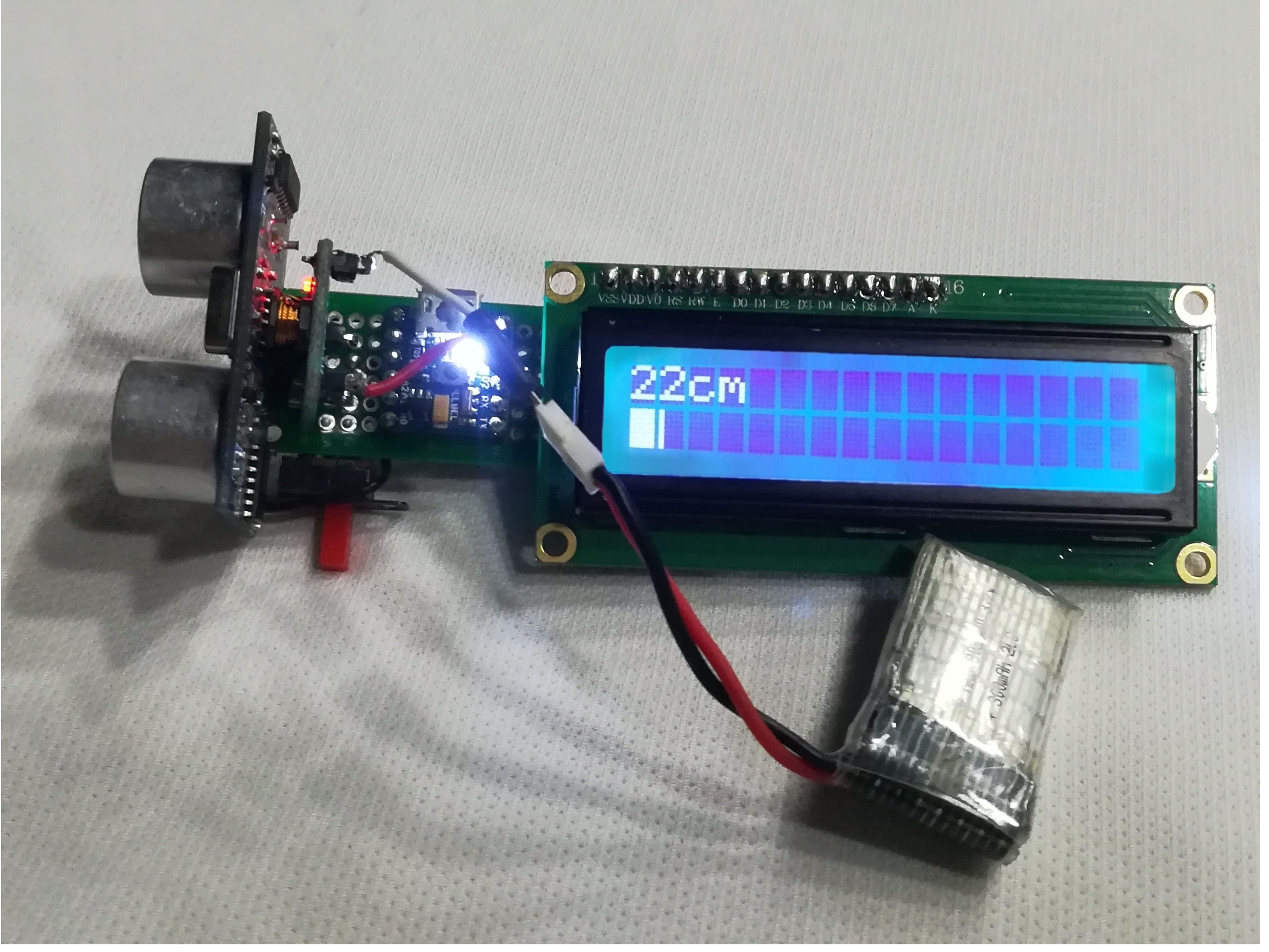
As you read this Instructable, you'll learn how to create a proximity sensor that you can use to measure distances between it, and whatever you point it at. It uses PICO, the Arduino compatible-board, and several other electronic parts that are already available in the market.
This was a personal project by our dear friend, Ala’a Yousef. To test the functionality of PICO in a rather simple project.
Components
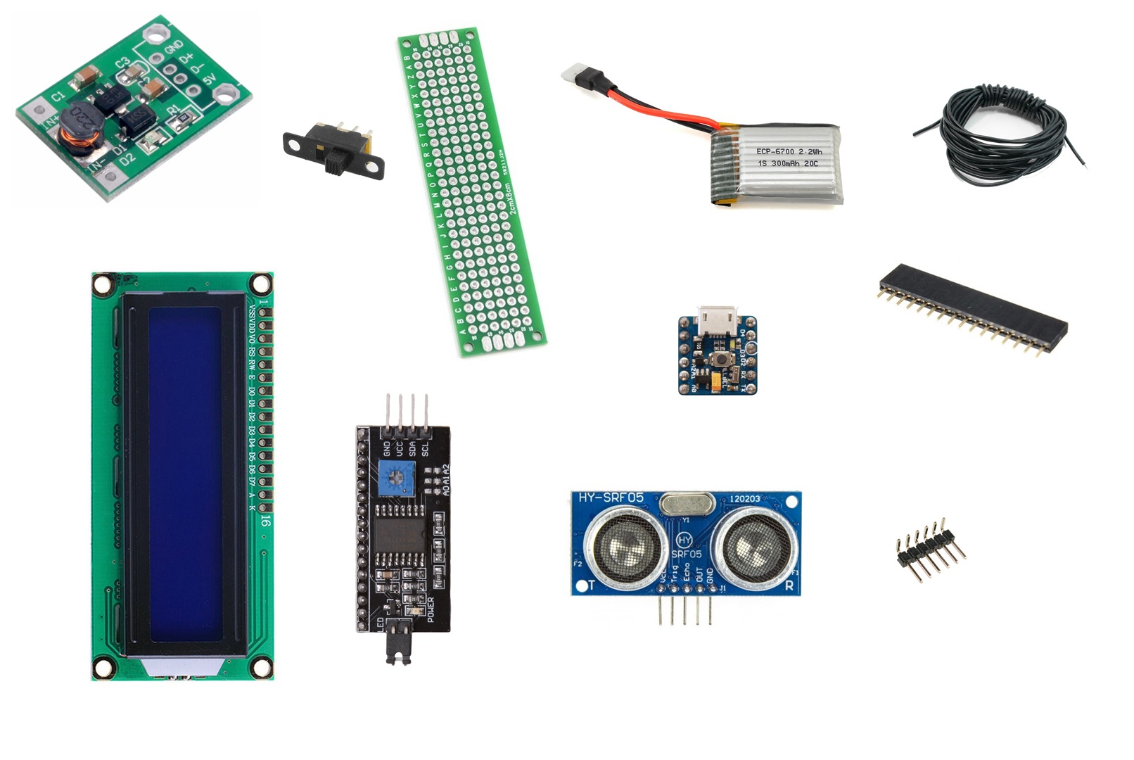
- DC-DC Boost Converter 3.3V-5V, ebay ($2.79)
- Wires
- A Slide Switch, a bundle of 5 at ebay ($3.83)
- 2x8cm stripboard, a bundle of 10 at ebay ($2.60)
- 3.7V 300mAh LiPO battery, ebay ($8.35)
- The well known SRF05 Ultrasonic sensor, ebay ($1.27)
- 16x2 LCD Display, a bundle of 10 at ebay ($7.99)
- LCD I2C Serial Interface Board. ebay ($0.99)
- 16 pin 2.54mm female straight header strip, a bundle of 20 at ebay ($1.85)
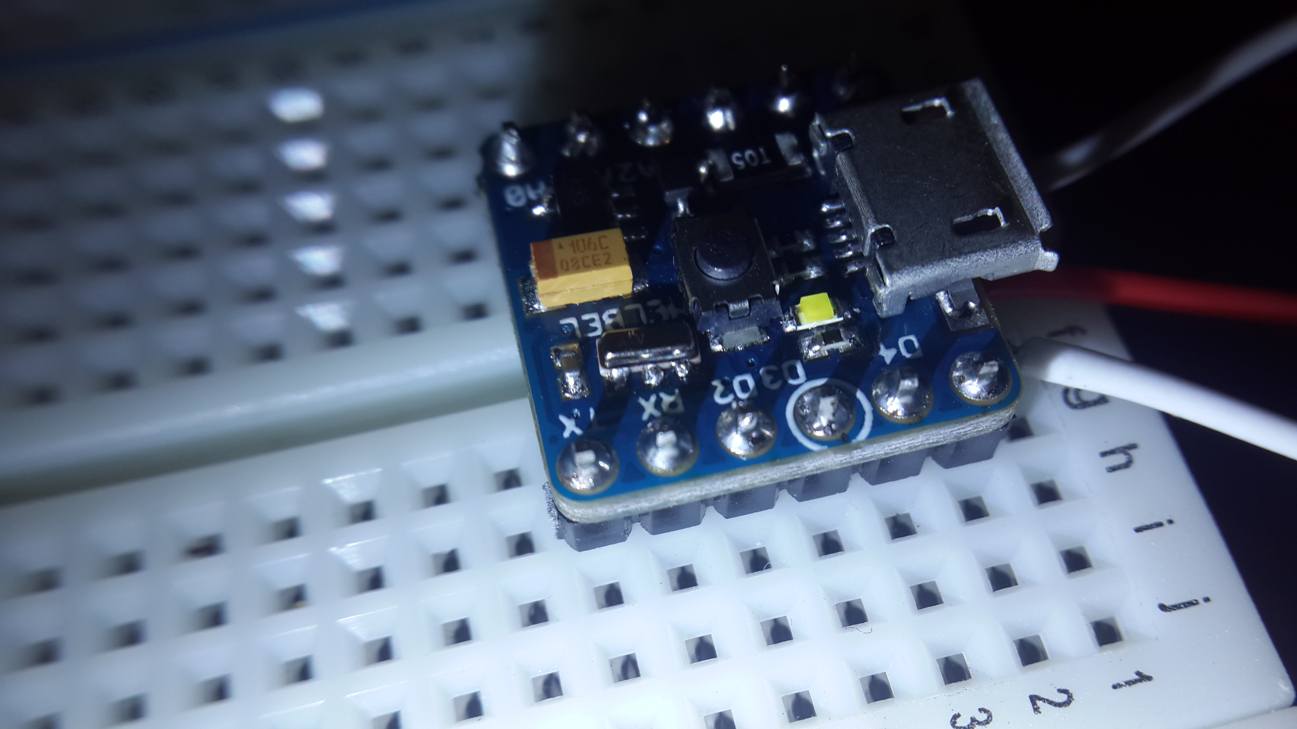
- The PICO development board. Available on mellbell.cc ($17)
- Right angle 2.54 pin headers, a bundle of 10x40pin at ebay ($1.99)
Preparing the LCD
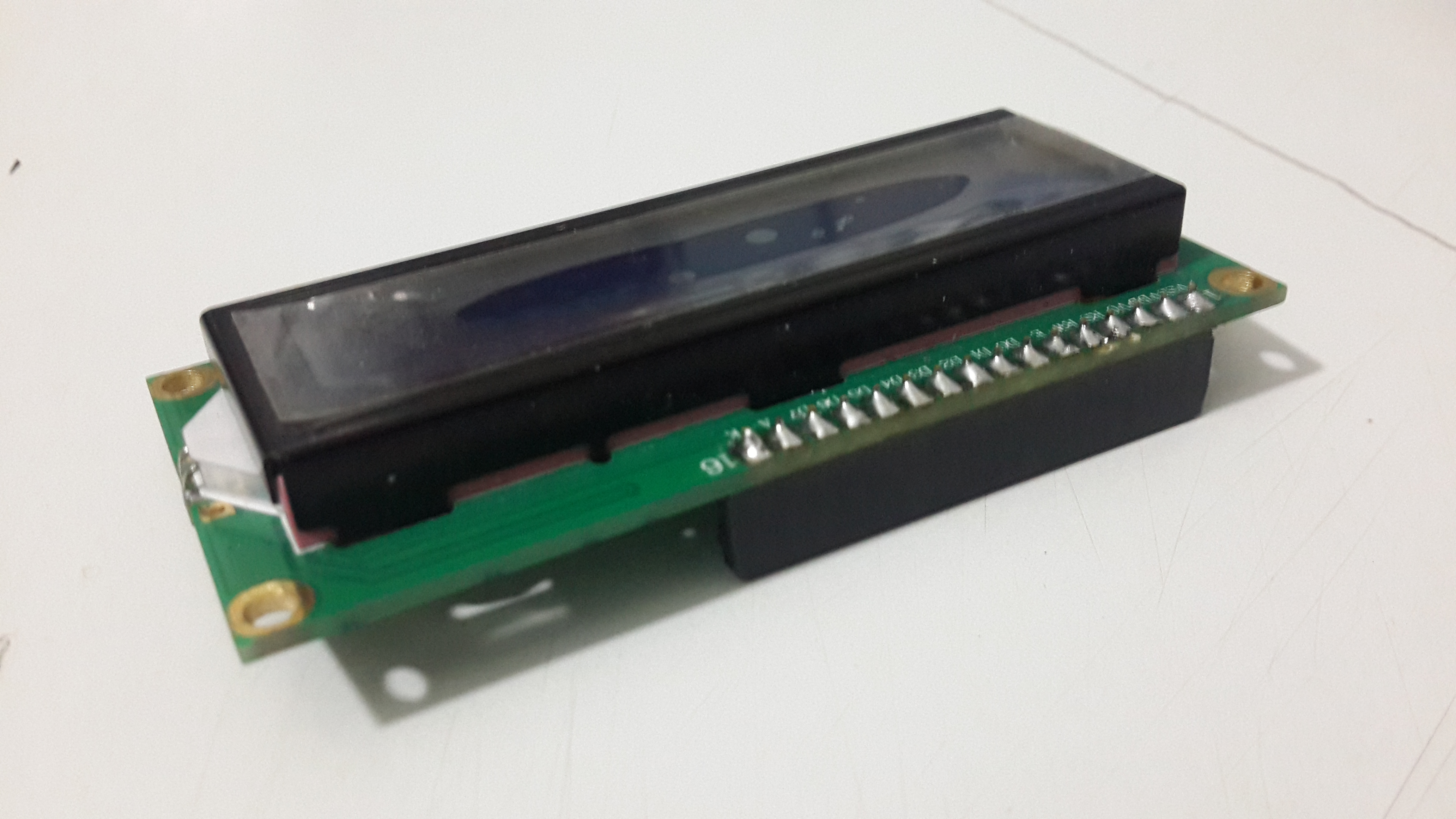
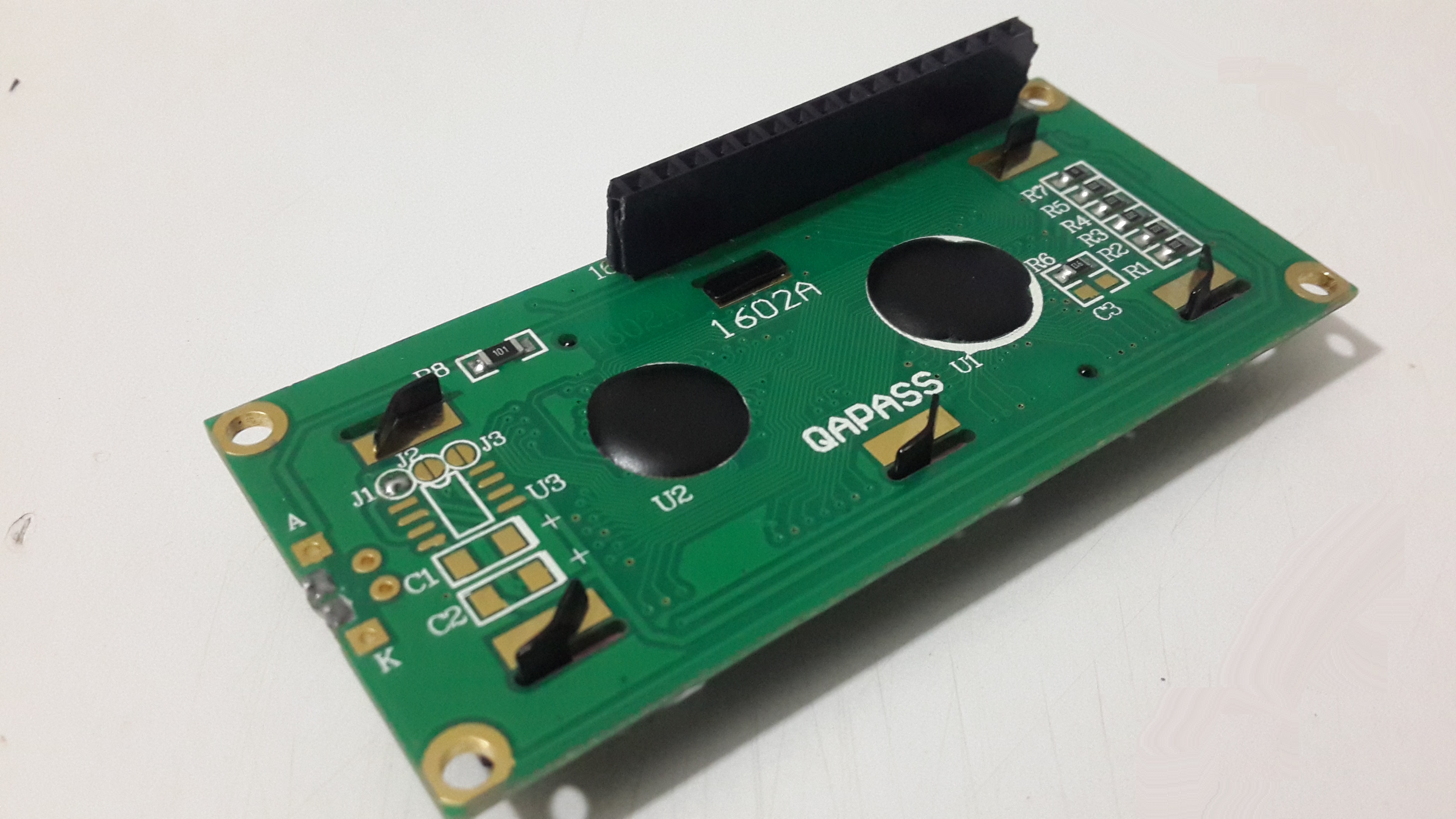
Here, you solder the female pin headers to the LCD pin-outs. It is recommended to do this instead of soldering the screen to the I2C module, so that you can have the flexibility of removing and replacing it with any other type of screen that you want to use.
Ultrasonic Placing
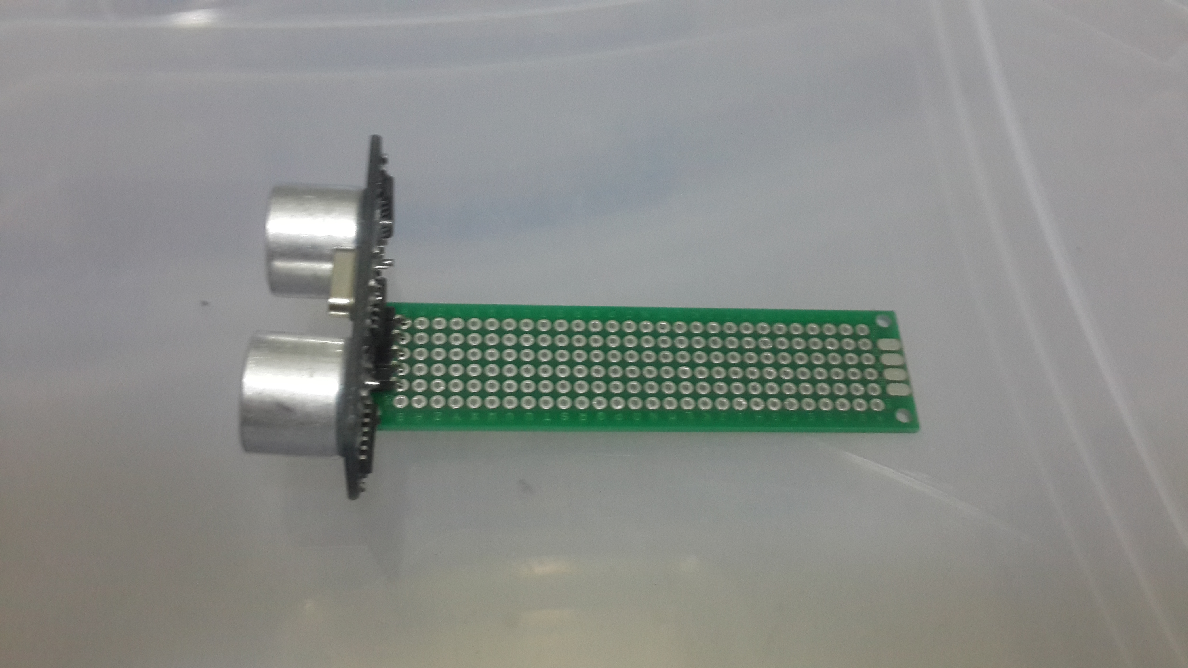
Solder the 5 pins of the ultrasonic sensor to the edge of the strip board, so that you get the biggest possible free area to work with.
I2C Module Placing
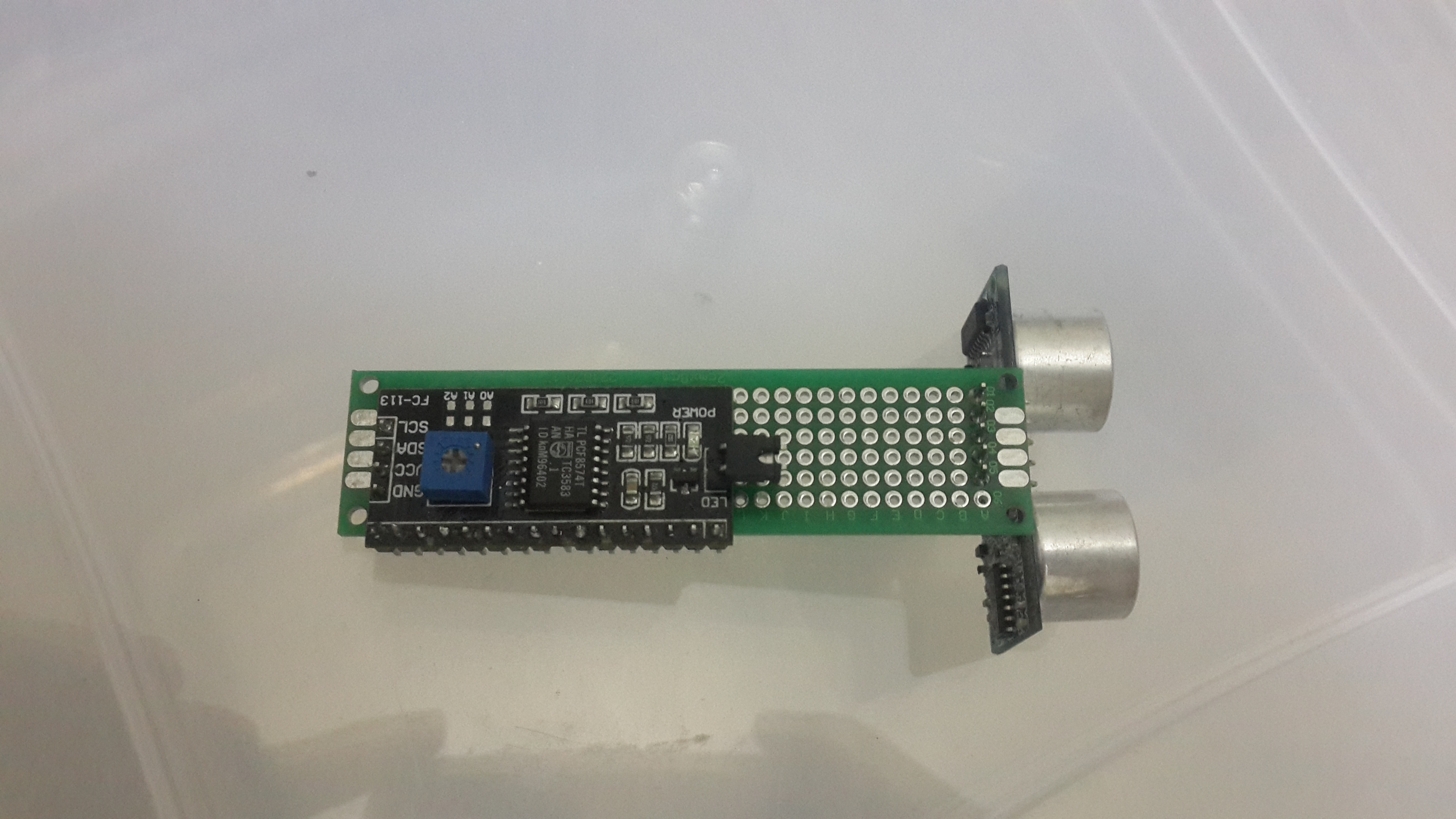
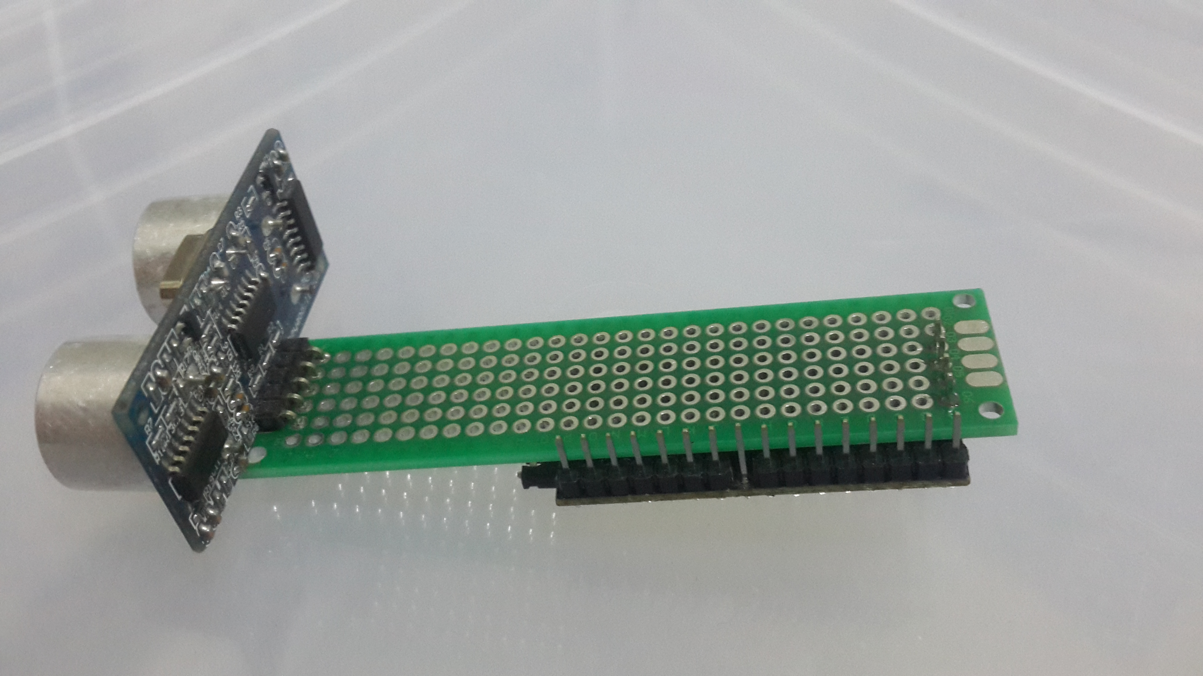
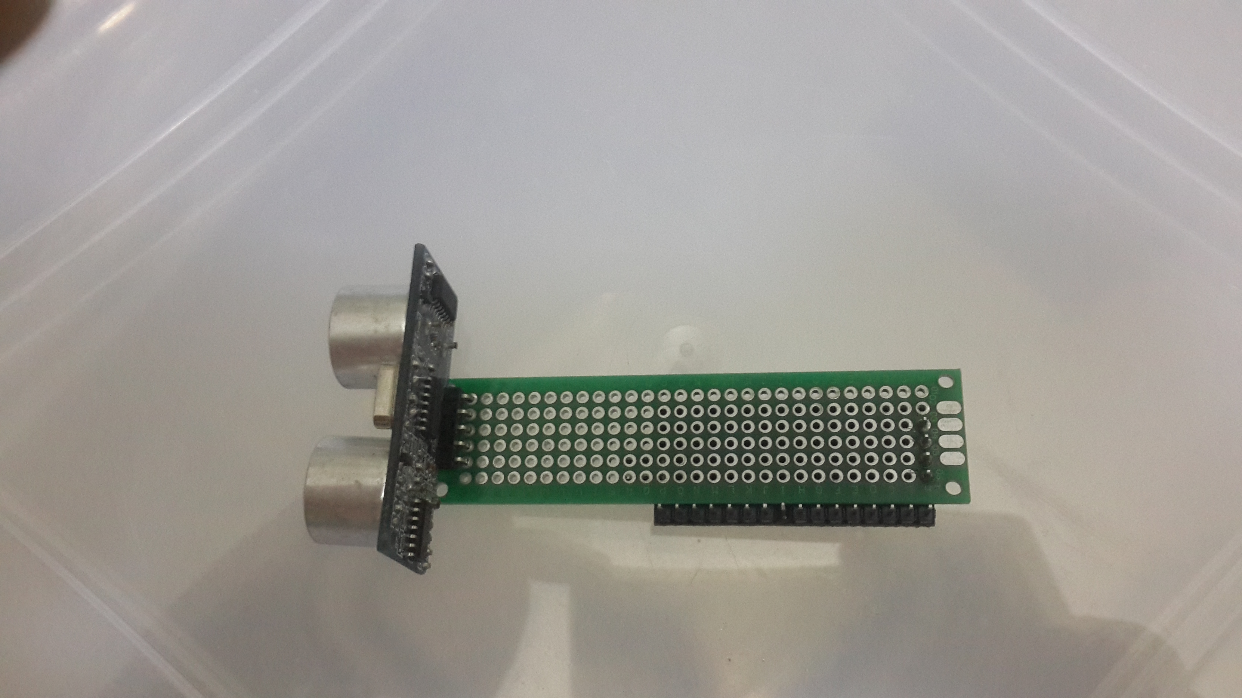
Place and solder the 4 pins of the I2C module (5V, SCL, SDA, GND) on the other side of the stripboard.
We do this to save more area on the top side of the stripboard for the remaining components.
PICO Board Placing
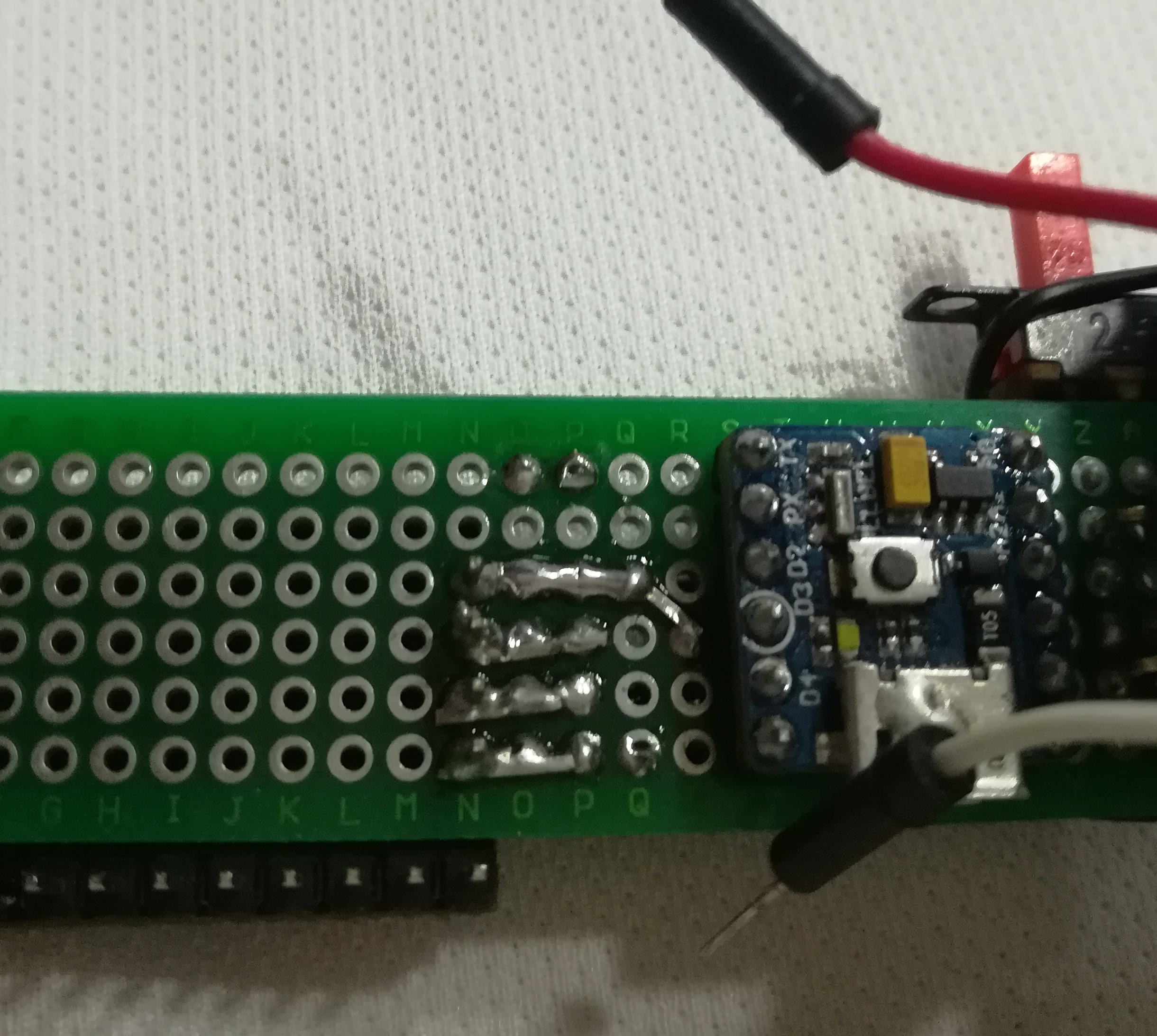
Place the PICO board right next to the four pins of the I2C module and leave at least four empty rows of the stripboard between the PICO and the I2C module pins.
Preparing the Boost Converter
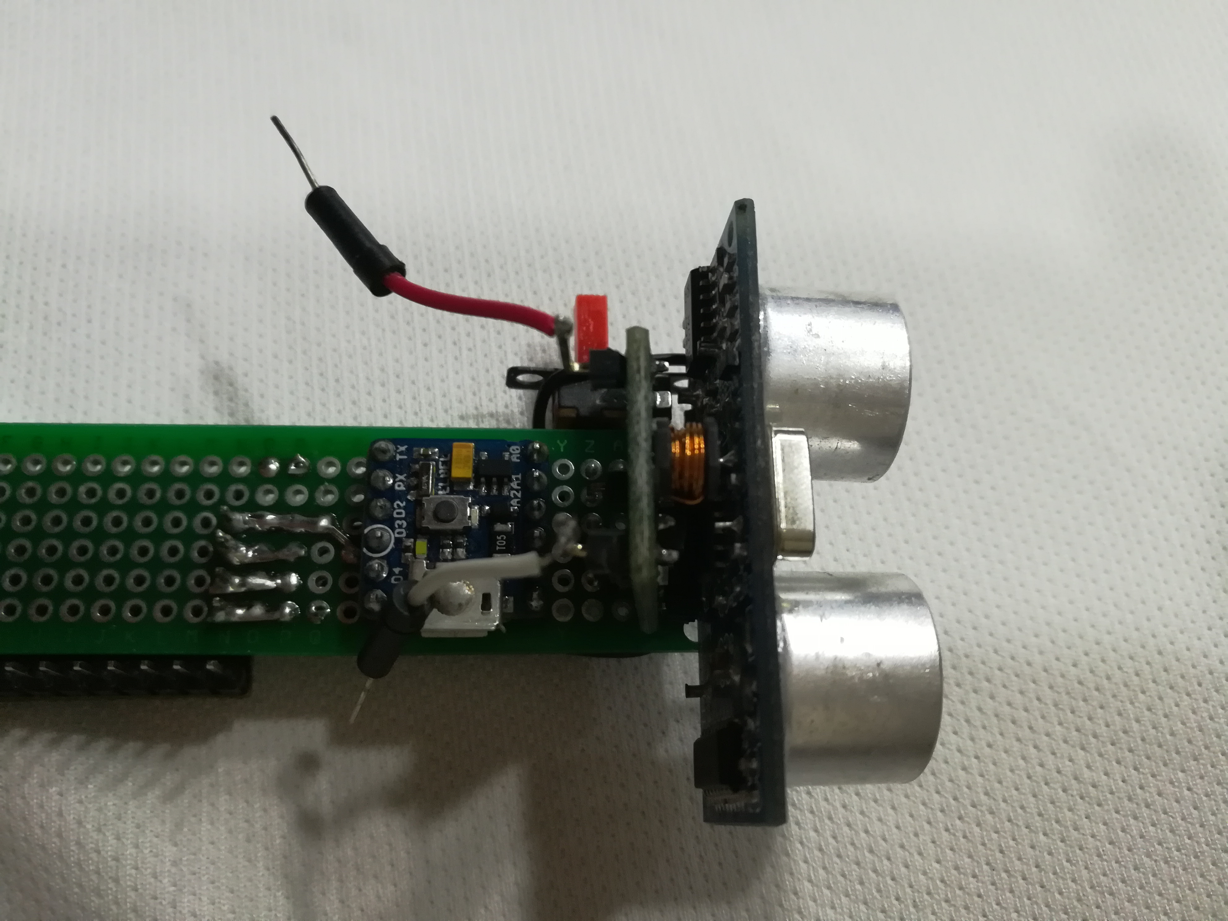
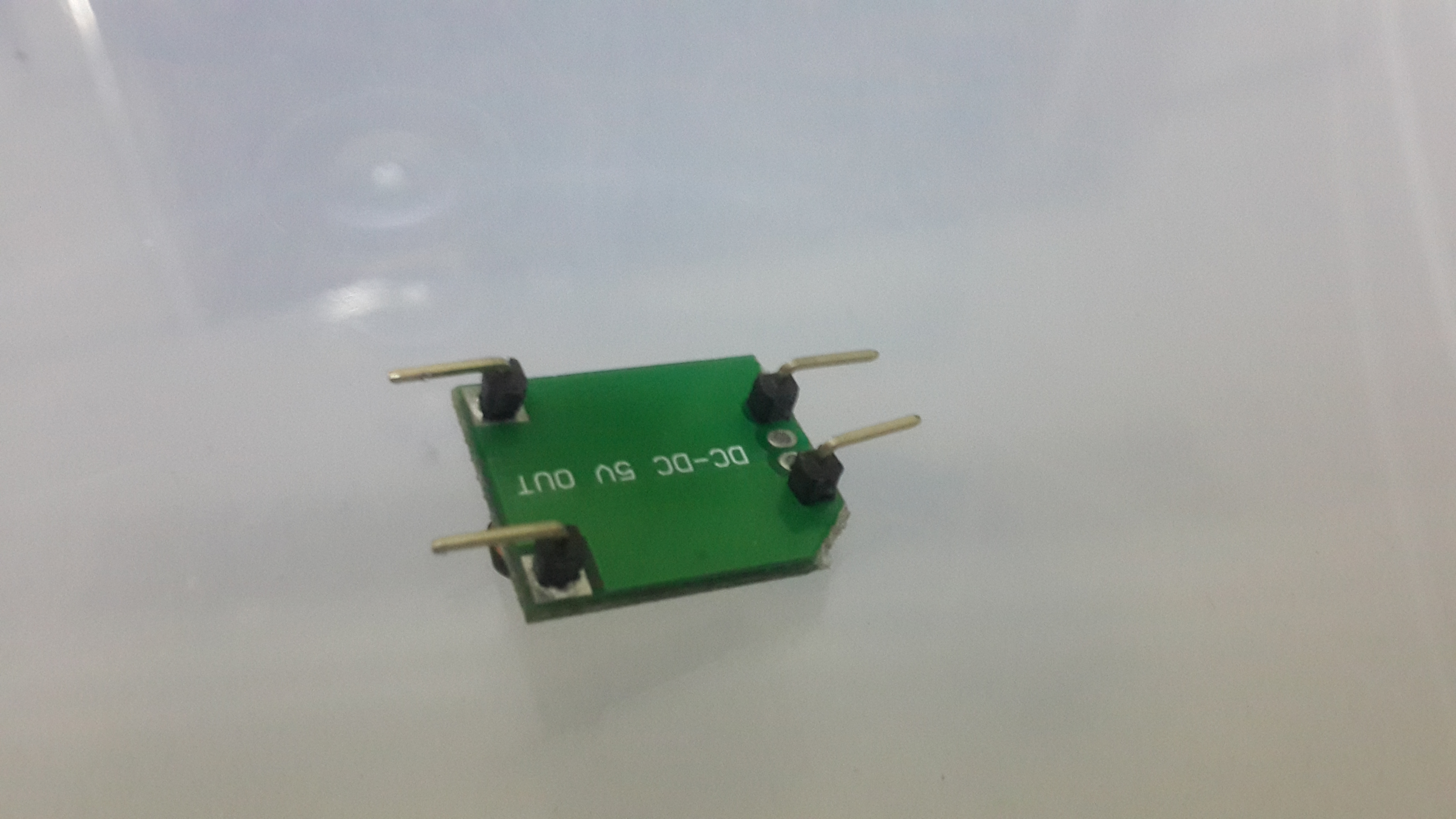
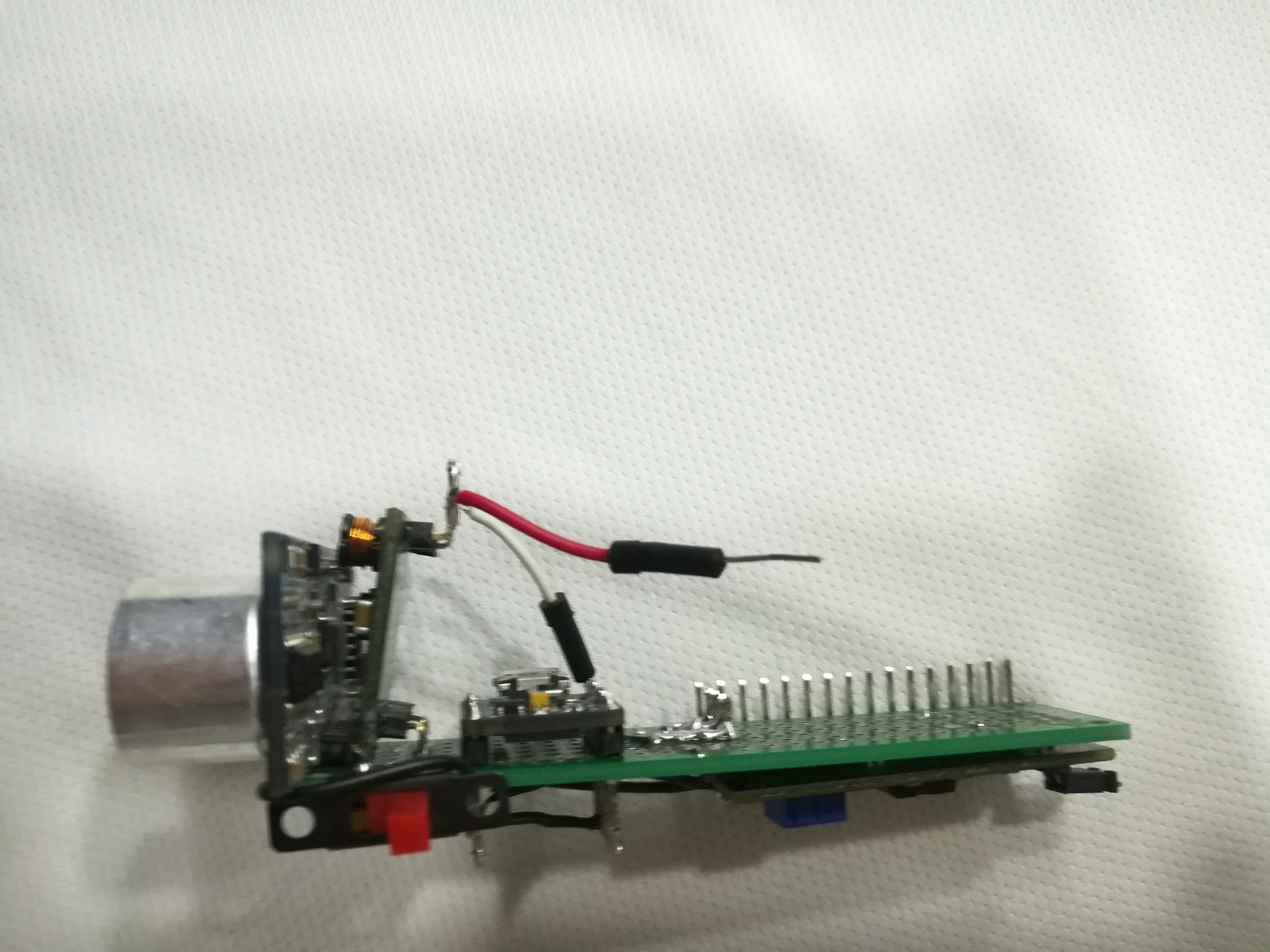
Pick the right angle pin headers and solder a single pin for each In+, In-, Out+, Out-. Because you need to put it in a standing position to save space.
Connections
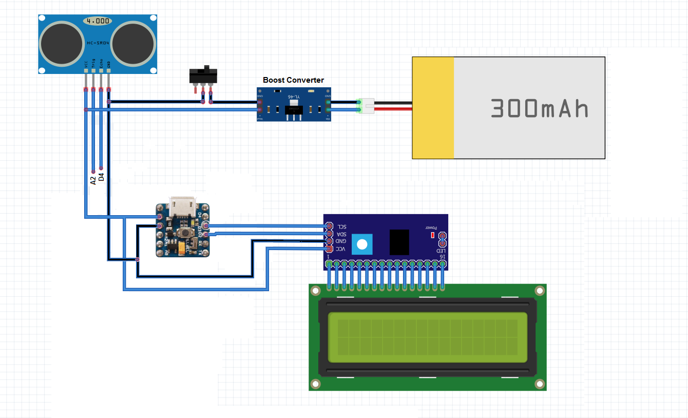
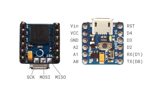
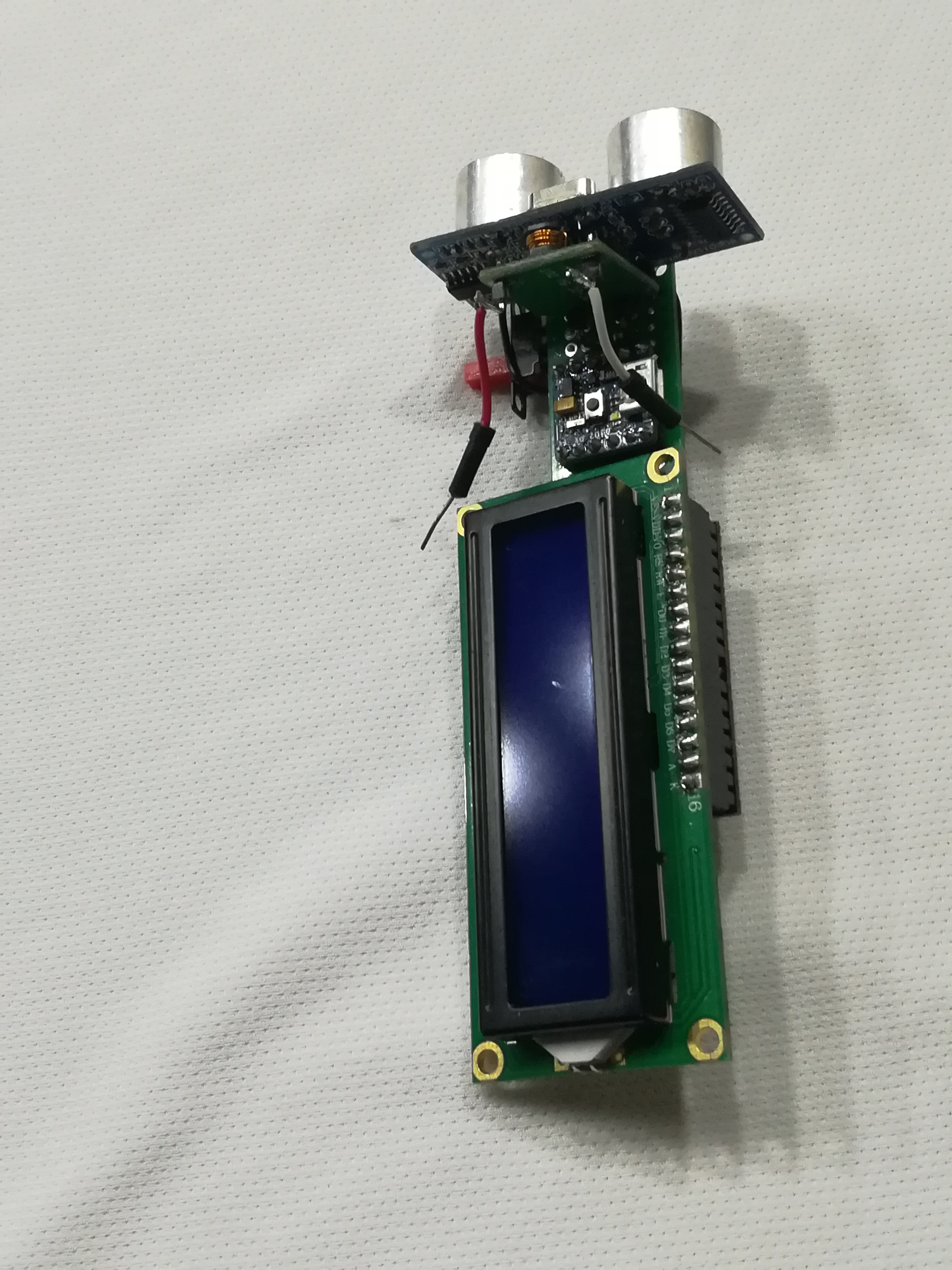
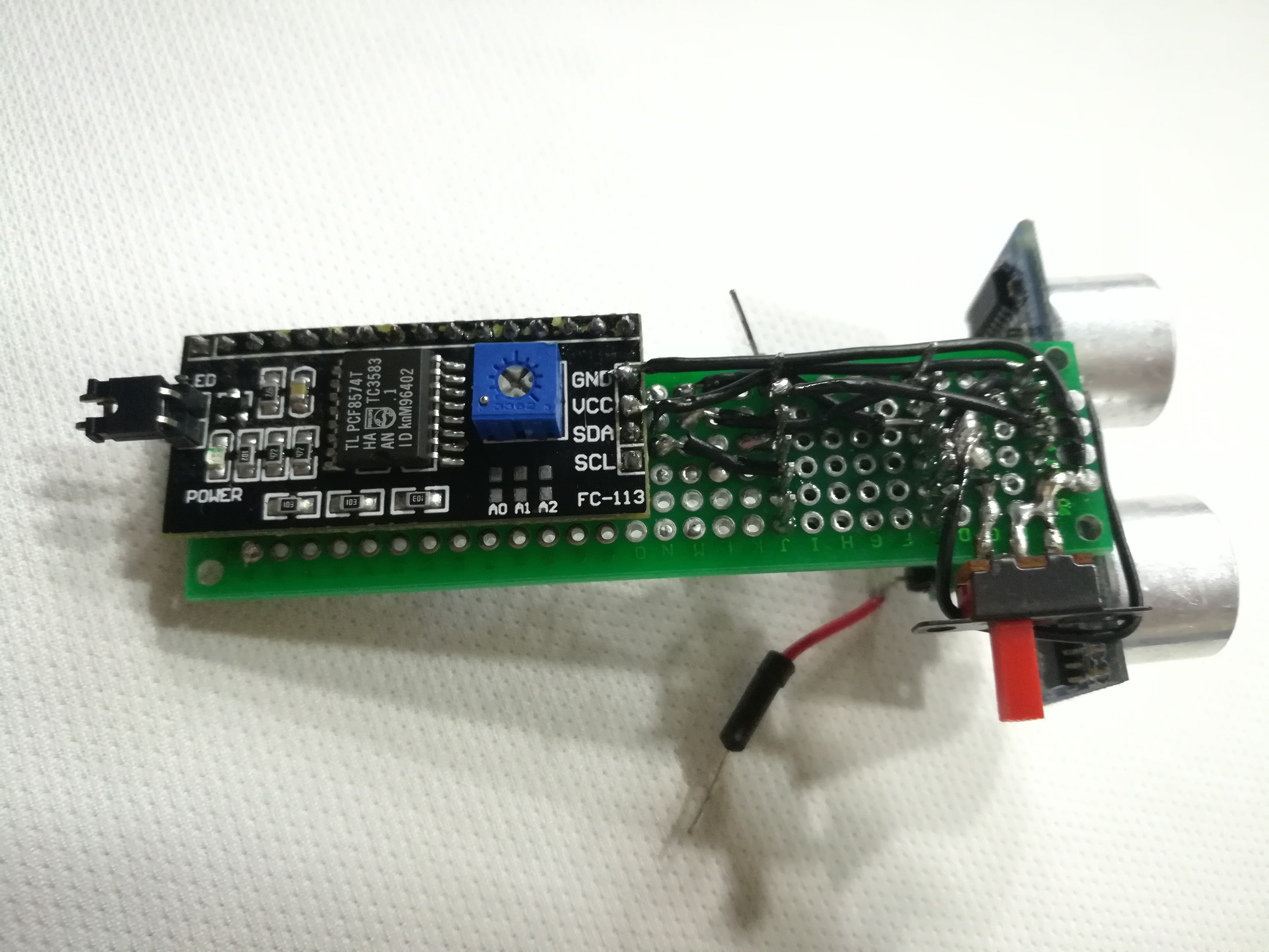
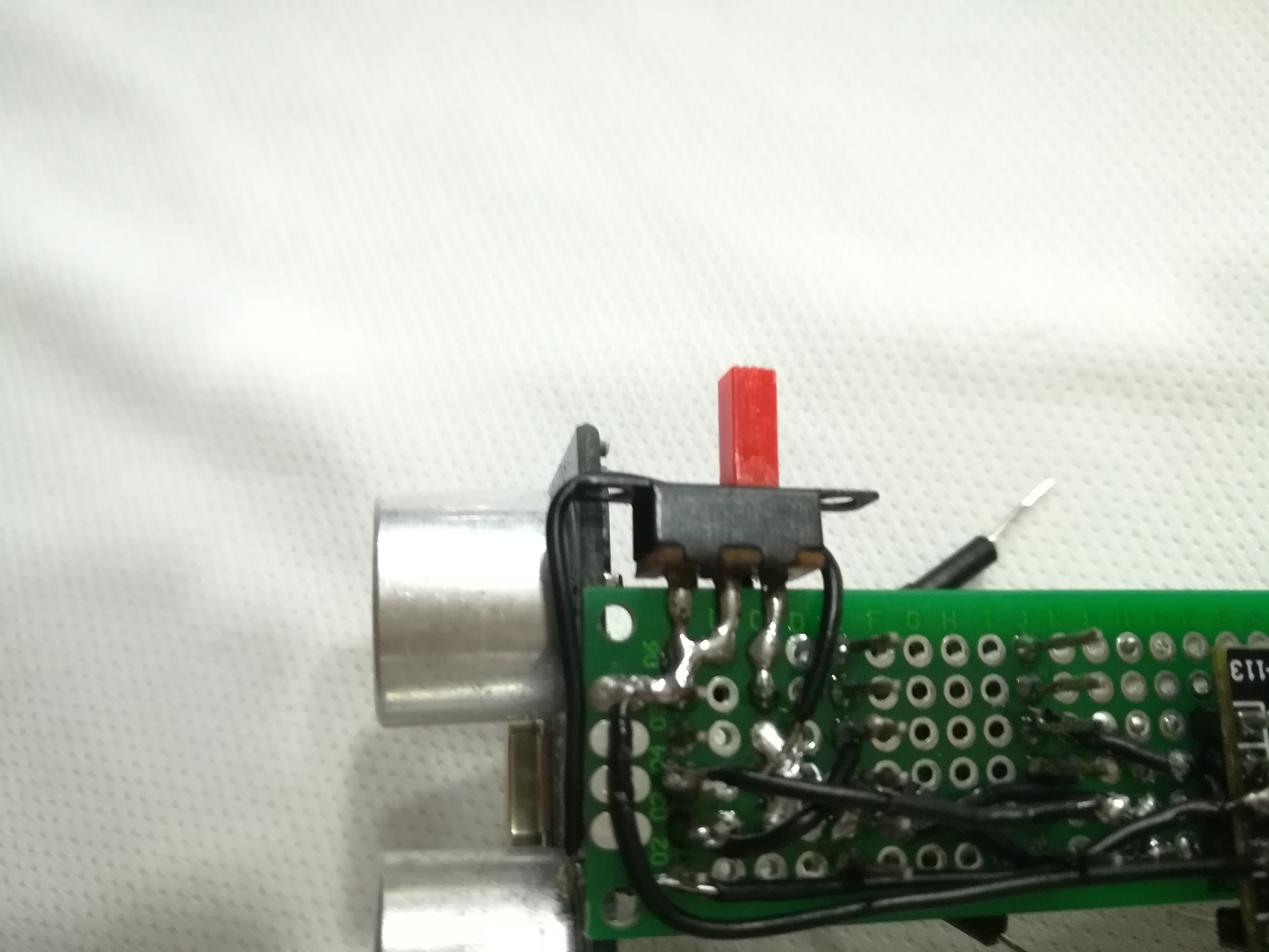
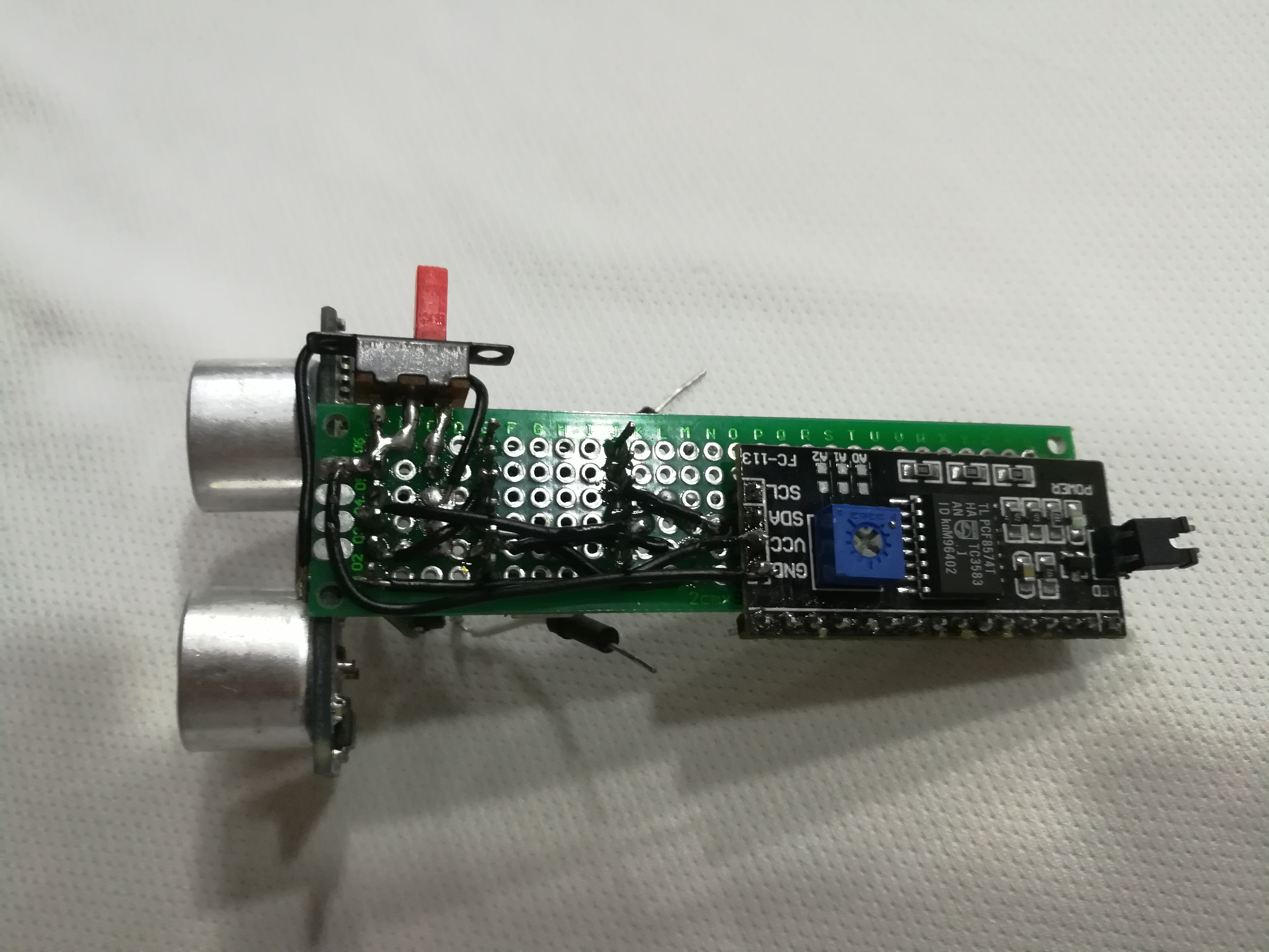
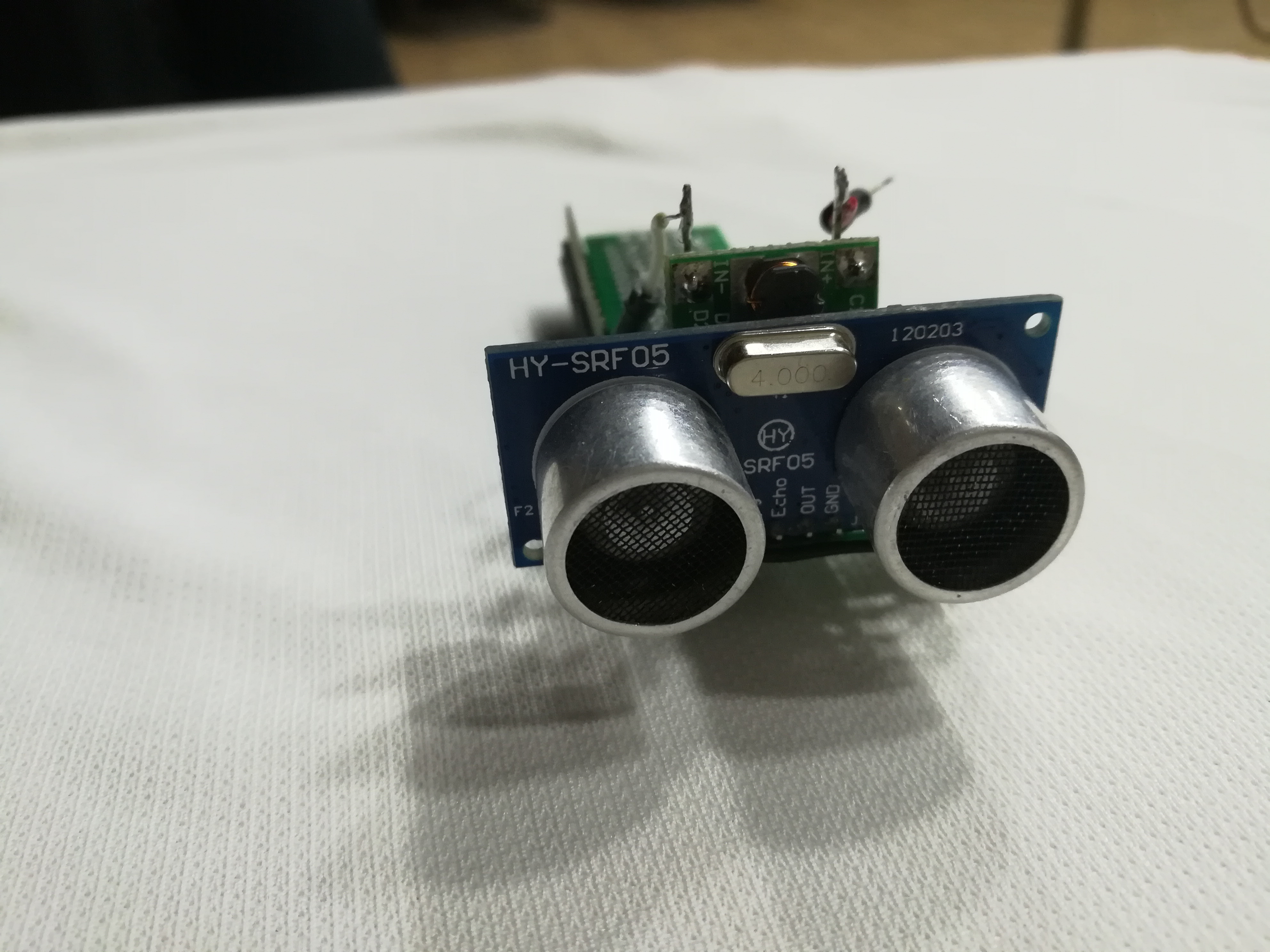
Connect your components as demonstrated in the pictures.
(Pin)_____________(PICO Pin)
SCL ......................... D3
SDA ......................... D2
Trig ........................... A2
Echo......................... D4
Vcc .......................... 5V
GND ........................ GND
Code
- "Distance_Measurement.zip" is the sketch file for the Arduino IDE.
- The rest of the files are libraries that must be included in the Arduino IDE. You can include libraries to the IDE by following these steps:
- Click on the "Sketch" menu in the toolbar
- Click on "Include Library"
- Click "Add .ZIP Library" and locate the zip file of the desired library
It Rocks!
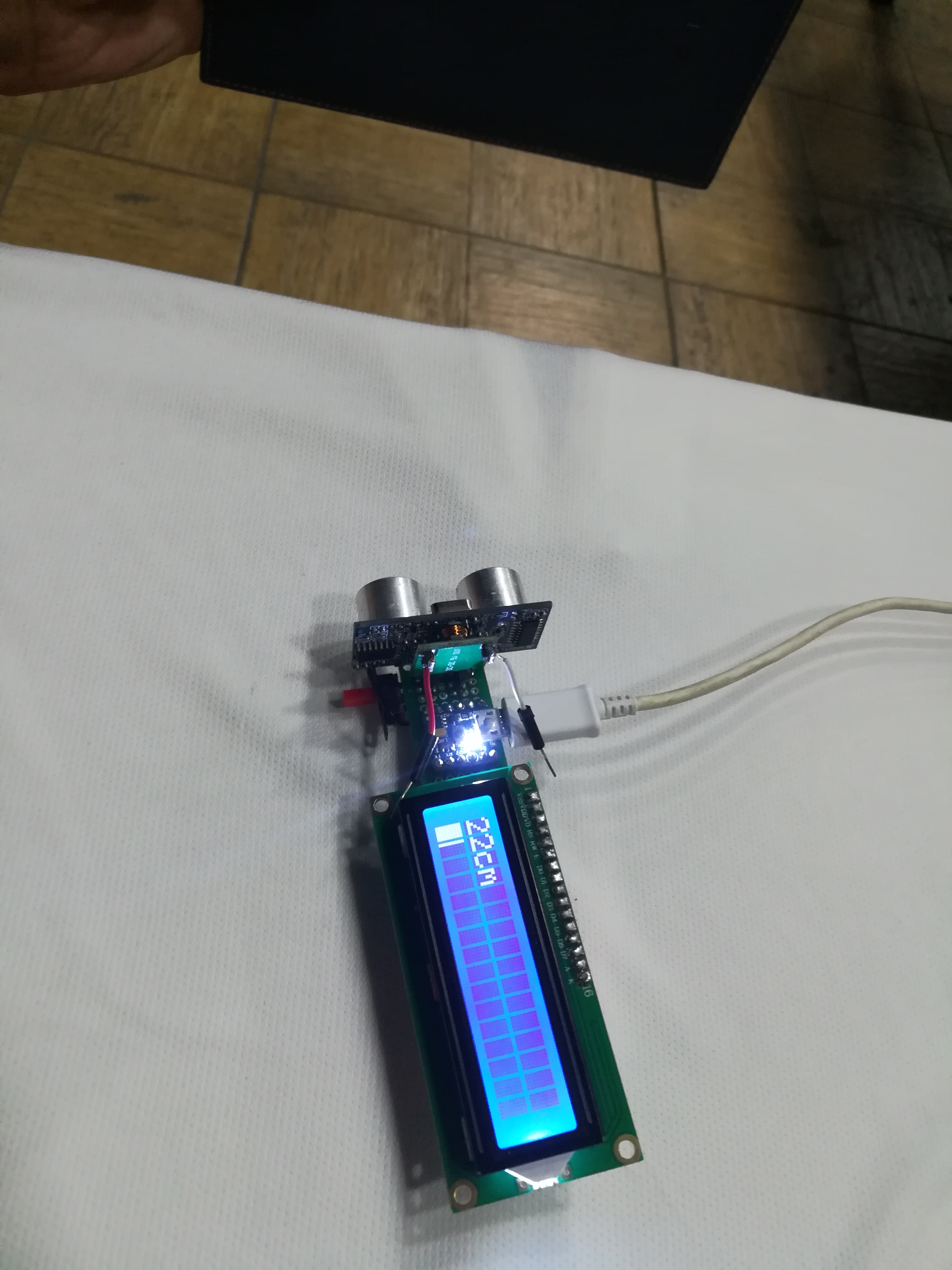
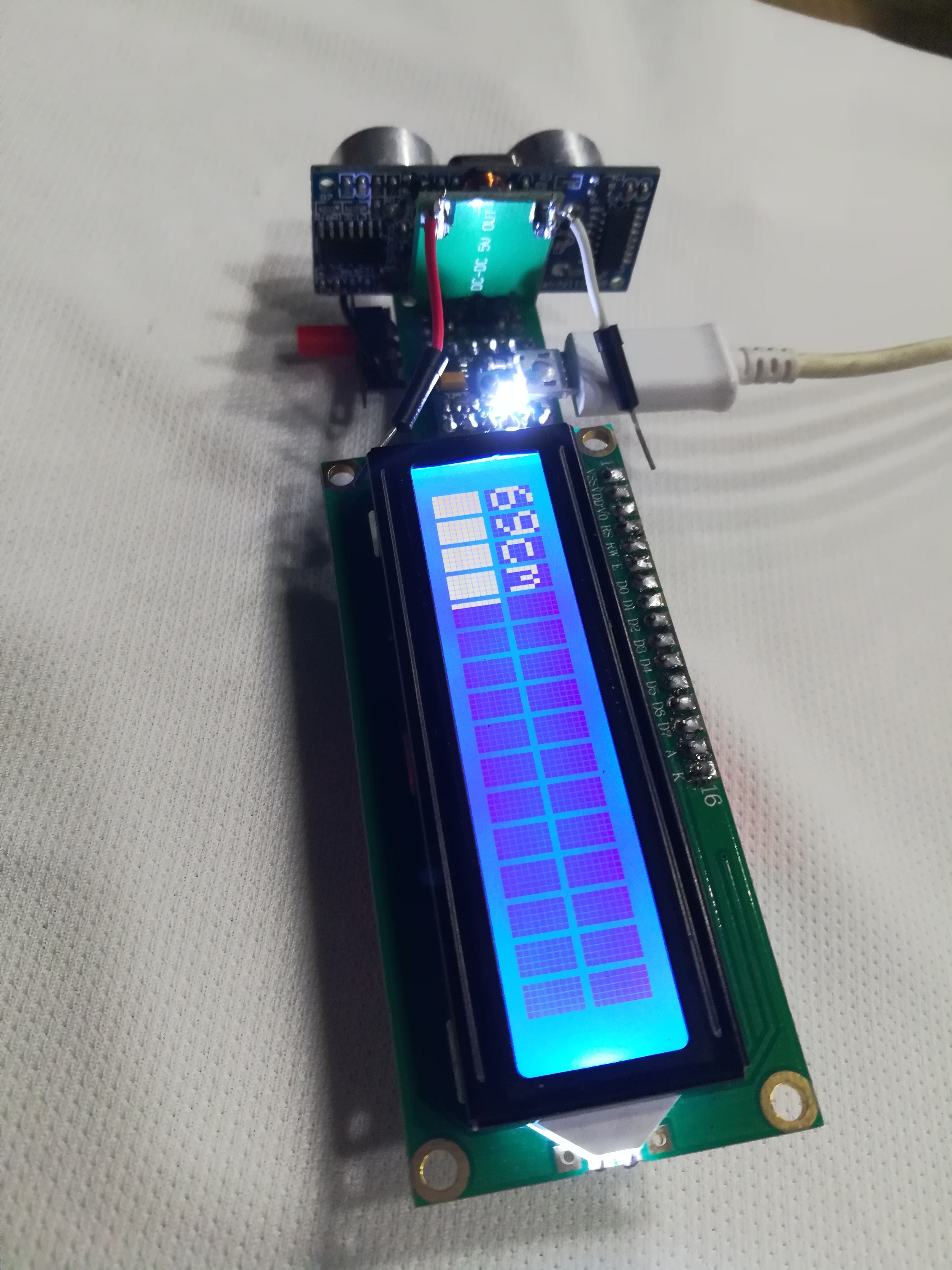
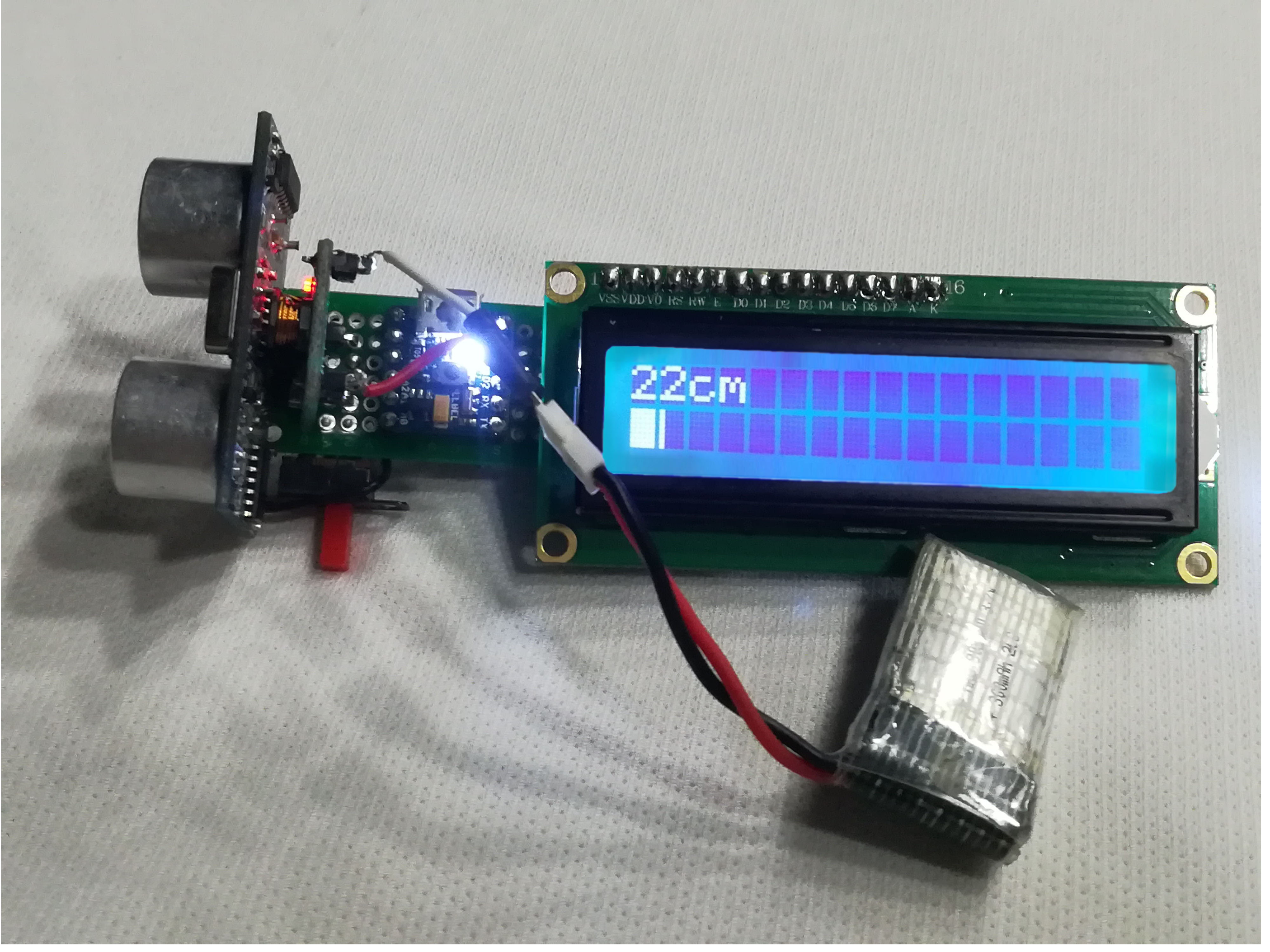
Now, you have a portable, pocket sized proximity sensor, that is ready to measure distances up to 5 meters. This was achieved by using PICO, which let us use a 2x8 cm stripboard instead of a larger board.