Polar Bloom Box: Adjustable Kaleidoscope-Inspired Box of Polarized Light
by lindsay36h in Circuits > Arduino
753 Views, 10 Favorites, 0 Comments
Polar Bloom Box: Adjustable Kaleidoscope-Inspired Box of Polarized Light
.png)
.png)


.png)

.png)
.png)
.png)
.png)
.png)
.png)
.png)
.png)


This project is created as a course assignment at the California State University, Long Beach; taught by Dr. Behnaz Farahi: DESN 586 Human Experience and Embodied Interactions Studio.
By Ritesh Adithya, Sean Corfield, & Lindsay Harrison
As you read through this section, take a look at the slides above.
Background
This project is a cumulation of an exploration of kirigami, polarized light, and physical interaction design. Initially, we set out to explore kirigami, which is the Japanese art of paper cutting. We explored many kirigami structures but were especially fascinated by one flower-like structure that spun as we pushed its sides inward. It seemed to play with our perception. To further explore this concept, one group member found a video by Steve Mould exploring an LCD filter found in an old laptop screen. The idea suggested by this group member was to use something like that LCD material to create these flower-like structures. From there, we explored polarizing filters, further playing with our perception. Playing with polarization and how it reveals hidden dimensions to our reality led us to this project.
Polarized Light
Light is electromagnetic radiation perceivable to the human eye. Although we interact with it constantly, most of us do not understand it. Our typical visual perception suggests light acts on a simple spectrum of color, brightness, and darkness. However, there are hidden complexities. Light is both a wave and a particle, with multiple components that may be manipulated to reveal hidden information.
Polarized light is light in which the electric field is oriented in one direction. A polarizing filter creates polarized light by blocking out movements in other directions. As such, this blocks an amount of that light. A polarizing filter acting on polarized light has the capacity to fully block out or fully let through all the polarized light, depending on its orientation.
Problem Statement
This project centers on the idea that our brains have a false intuition of how light works since we do not perceive light itself but the objects that light reflects off of (Marr, “The Philosophy of the Approach”). Additionally, our brains can even be fooled as one display of light on the retina can have multiple object interpretations within our brains (Kellman & Arterberry, “The Cradle of Knowledge: Perceptual Development in Infancy”).
Thus, despite our reliance on visual perception, most people do not have an intuition of the role our brains play in interpreting our surroundings, nor the complexities of light on a physical level.
Project Goal & Target User
We want to demonstrate how light can be separated to illuminate new information and to give viewers an improved intuition for how light and our brains interact. This project’s target user is students of all ages (though most likely students ages 7 and older) who are curious and drawn toward mind-bending effects.
Case Studies
To think about our design, we consulted the work of Daniel Rozin and Maria Constanza Ferriera at the San Francisco Exploratorium. Their works are linked here:
Inspired by “Crystal Paintings,” we thought of having a moving or adjustable piece that showed the polarizing view of a scene. Inspired by “RGB Lights Mirror,” we wanted the view itself to adjust based on movements from the user.
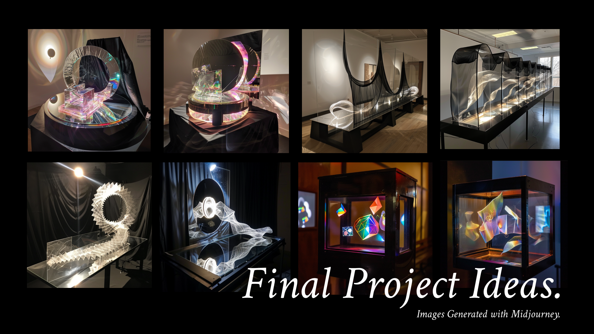
Ideation & Sketches
We knew that we wanted to use polarizing filters, plastic objects, and a mirror to demonstrate our desired effect. However, we didn’t know what the final product would look like. We visualized some of our ideas with Midjourney and sketched out several ideas we thought would work (see images above). Ultimately, we decided on the structure of a box with a lazy susan since it would be a more intimate experience for the user; we liked the idea of peering into another world through a hole. Furthermore, this idea would be most easily implemented on a smaller scale.
User Interaction
The user will look down through a polarizing filter to a scene set by an LED screen, mirror, and small plastic sculptures. The user can twist the filter to adjust the view. The user can also remove the filter and switch it for another filter with a different polarizing filter pattern to see another view. There will be three interchangeable filters, each of which can also be adjusted left or right.
Project Technologies
- p5.js
- Arduino
- Raspberry Pi
- Laser Cutting
- Craft-work
Construction Overview
- Acquire materials.
- Set up p5.js and Arduino.
- Transfer p5.js and Arduino code to Raspberry Pi & LED Screen.
- Laser-cut and assemble the box.
- Situate Raspberry Pi & mirror setup in the box.
- Assemble interchangeable filters.
- Assemble small plastic sculptures.
- Finishing touches.
Finished Product
View our videos to see the finished product and process.
Supplies
- Arduino kit
- (optional) Raspberry Pi
- Raspberry Pi LED screen
- Black acrylic sheet (18” x 18”)
- Small mirror (17cm x 9cm or similar)
- Polarizing filters (x4 11” x 8.5” sheets recommended)
- 2-inch diameter lazy susan
- 1/16-in wooden dowels (x2 recommended)
- Black acrylic paint
- Kitchen shears
- Hot glue gun & glue sticks
- Superglue
- Leftover plastic waste (we used leftover Lego packaging bags)
- (optional) Desk lamp
Set Up P5.js & Arduino


This first step will require you to download the following:
- The code files attached below (see folder).
- (Optional) Visual Studio Code - https://code.visualstudio.com/download
- p5.serialcontrol - https://github.com/p5-serial/p5.serialcontrol/releases/tag/0.1.2 (download “win32” zip if you are on Windows or the “darwin” zip if you are on Mac)
- Arduino - https://www.arduino.cc/en/software
To begin, download the folder attached below. These files were based on an online source, and we received some additional help with them. Please see folder file comments for proper citations.
If you would like to view the code in detail, set up the files in Visual Studio Code. Here is a link to download VS Code. To use p5.js in Visual Studio, go to the extensions tab (on the left navigation bar it’s the second icon from the bottom), and search for “p5.js”. Add the extension from there. After that has been done, click the top-most icon on the navigation bar, and choose “Open Folder.” Open the folder you have downloaded from this website.
This is optional, however, as you can use terminal controls to make the code run. Please see read_me in the folder below.
Next, we need to set up the arduino component. With your arduino kit, set up a circuit that follows the circuit in the diagram above. This circuit’s main point is to allow your computer to read data from the light sensor. If you need additional help with your arduino setup, please consult this link. (Note: please still follow the circuit diagram shown above, use this as an additional reference only)
After setting up your arduino, plug it in and open up the Arduino software on your computer- download it here if you have not yet done so. Additionally, make sure you have downloaded the arduino file provided below. From the Arduino software, open the provided file, please see read_me in the folder for more information (go to “File” -> “Open” at the top of the window). Once the file has been opened and your arduino is connected, verify and upload the code to the arduino (top right two buttons on the window). If you face difficulties running the code, it may be due to your port settings. Please see this link for further help.
Now that the arduino has been set up to receive outside information, and the p5.js is setup to respond to that information, we just have to connect the two. Download p5.serialcontrol if you have not yet done so from here. After opening p5.serialcontrol, scan your ports and open the one your arduino is connected to. Please see this link for further assistance.
Finally, once p5.serialcontrol has connected the arduino to p5.js, please follow the instructions in read_me if you did not download Visual Studio Code. It will instruct you to run a provided file via your computer's terminal.
If you downloaded it, go back to Visual Studio where you should have the downloaded folder open. Check the code and setup work properly by selecting “Go Live” in the bottom right corner. This should open a window in your browser displaying the code, which changes depending on information the light sensor picks up. Move your hand closer to and farther away from the sensor to see the code change.
Please download this entire folder:
Transfer P5.js & Arduino Code to Raspberry Pi & LED Screen (Optional)
To run p5.js and the Arduino code in one system, we will now transfer the p5.js and Arduino setup to a Raspberry Pi. Please note that this step is optional. You can take the Arduino setup and place that inside the finished box as well, but you will need a long USB chord to connect the Arduino to a personal computer, and you will still need the Raspberry Pi LED screen. The screen will also have to be connected to a personal computer and display the browser display. For the box to exist independent of a personal computer, see below steps.
In this step, you will have to set up your Raspberry Pi, make a simple web server on the Pi, run the p5.js code via p5.serialserver, and use the Raspberry Pi serial ports (GPIO) to connect the Arduino light sensor to the system.
To complete these steps, please see this link - the instructions are more detailed than the room available here. Follow these steps, but use the folder we provided from the previous step when linking your p5.js project to the Rasberry Pi.
Laser Cut and Assemble the Box


Now that the visual display has been set up, we need to house it in a structure. Four Adobe Illustrator files have been provided below. These will provide you with the setup for a box 6.8” x 3” x 5” box. Take these files to a local laser-cutter and have the box made for you using an 18” x 18” black acrylic sheet.
Once the box has been cut out, assemble the box by pushing together matching sides. However, do not yet place on the top piece of the box (the one with the circular hole cut in it). Please note the photo above is what it should look like once completed- the circular hole should be facing up- though we suggest not putting that piece on yet. Additionally, please note that some force may be necessary to push some sides together, but once together, the box will hold its shape without any glue necessary.
Situate Raspberry Pi and Mirror Setup in Box


The next step is to place the LED screen and small mirror in the box. Before placing the mirror in, you will want to set a layer of polarizing filter on top of the mirror's surface. Take a sheet of polarizing paper and hold it above the LED screen (the LED screen should be on). Rotate the polarizing paper about 45 degrees or such that the filter lets the LED light through. In this orientation, cut out a piece of polarizing filter the size of the mirror and set that on top of the mirror. Place both such that one side sits in the well cut out in the bottom of the box, and the top of each rests on either wall. Make sure the side of the LED screen with the HDMI port is facing the large hole cut out from the back side, so you can connect that to the Raspberry Pi and power source. Please see the images above.
Additionally, during this step, ensure the light sensor is attached to the raspberry pi. Note that this light sensor will be attached to the top piece of the box, though we will hold off on doing that for now.
Depending on your preference, you can raise the mirror up to be better situated in the viewing hole, using a wad of tape or something similar. We did this, though it is not necessary.
Assemble Interchangeable Filters and Lazy Susan


During the laser-cutting step, you should have made 3 rings. In this step, we will create interchangeable filters and attach a lazy susan to the top of the box (with the circular hole in it).
To create the filters, cut three 2 ½” diameter circles, or three circles slightly larger in diameter than the rings themselves. Glue each one to one slide of the ring, specifically gluing each inner circumference of the filter to each outer circumference of one side of a ring. Now that you have three filters, set one aside as your “basic” filter. With the other two, (using superglue) glue strips of polarizing filter on top of the filter glued to the ring. This will produce even stranger visual effects. Feel free to be creative here and make your own patterns with the filter, or follow ours as shown in the photos above. Since the point is to change the view, we recommend creating two different patterns on the two rings.
After the filters have been created, it’s time to attach the lazy susan. Using the hot glue, glue the lazy susan on to the top piece of the box such that the holes are aligned. Once the glue has cooled, we need to add dowels to the lazy susan’s smaller, outer holes to hold our interchangeable rings in place. With the 1/16” wooden dowel, cut one ½“ to 1” piece. Feel free to paint it black to make the final product more aesthetically pleasing. Finally, hot glue the small wooden dowels to one small, outer hole of the lazy susan. There are four of these holes - make sure you glue it in place so it can still rotate, hold the filter, and be held by fingers.
Assemble Small Plastic Sculptures

This step is optional. An alternate but easier idea is to crumple up old plastic packaging and set that in the box instead for a more disorganized but beautiful interior look.
During this step, you will have to remove the top piece of the box if you have not done so (the piece with the circular hole in it). Using wooden dowels, black acrylic paint, hot glue, scissors, and plastic leftover material, make little plastic sculptures. The plastic in these sculptures will have an interesting effect in the final product. In this step, feel free to be creative and make your own sculptures. We will describe how we made ours below:
- Cut the wooden dowel into ½” to 1” pieces.
- Shave off the sides of the ends of each piece so they are flatter.
- Paint the pieces black with acrylic paint.
- Glue together the flat ends of 3 pieces to form a triangle.
- Cut out an appropriately sized triangle from the leftover plastic material.
- Glue the plastic triangle to the wooden triangle structure.
- Repeat steps 4-6 multiple times.
- With multiple of these triangle structures completed, glue them together to form 3D sculptures.
Finishing Touches


.png)
Almost done!
In this final step, we will put everything together. If you completed Step 2, connect the LED screen to your Raspberry Pi, and connect that to a power source. If you skipped Step 2, place your Arduino in the box while it is connected to a personal computer. Additionally, connect the Raspberry Pi LED screen to your computer and ensure that is displaying your desktop. We used long chords for both of these. Ensure the LED screen is on and displaying the code. Next, drop the plastic sculptures into the valley between the LED screen and mirror.
Next, put the top piece (with the lazy susan) on the box, but do not push it into place quite yet. Now, we will attach the light sensor to the top piece of the box. Tape the sensor such that it just peaks into the circular hole, and you must tape a small piece of polarizing filter over it. Ensure this small piece of polarizing filter covers as little area as possible but covers the light sensor. Additionally, do not tape the filter to the light sensor itself, but connect it to the lid while adjusting it such that it rests over the light sensor.
You can print out these educational pages (double sided on a piece of paper) and set it next to the box for users to engage with.
Finally, push the top piece of the box into place. Make sure the box is set up in a well-lit environment (we put a lamp to the side), and make sure the interchangeable filters are within reach.
And with that, you’re done! Invite users to explore the intricacies of light with your box.