Pocket-Sized Thermal Imager + Infrared Thermometer
by RoboticWorx in Circuits > Tools
23143 Views, 291 Favorites, 0 Comments
Pocket-Sized Thermal Imager + Infrared Thermometer

For the best quality read, check out this article on my homepage here. Also, don't forget to subscribe for free to support my work! :)
In this project, I will explain how to build a highly precise thermal imager/ranged infrared thermometer that you can use for various sensing applications.
A Quick Preview
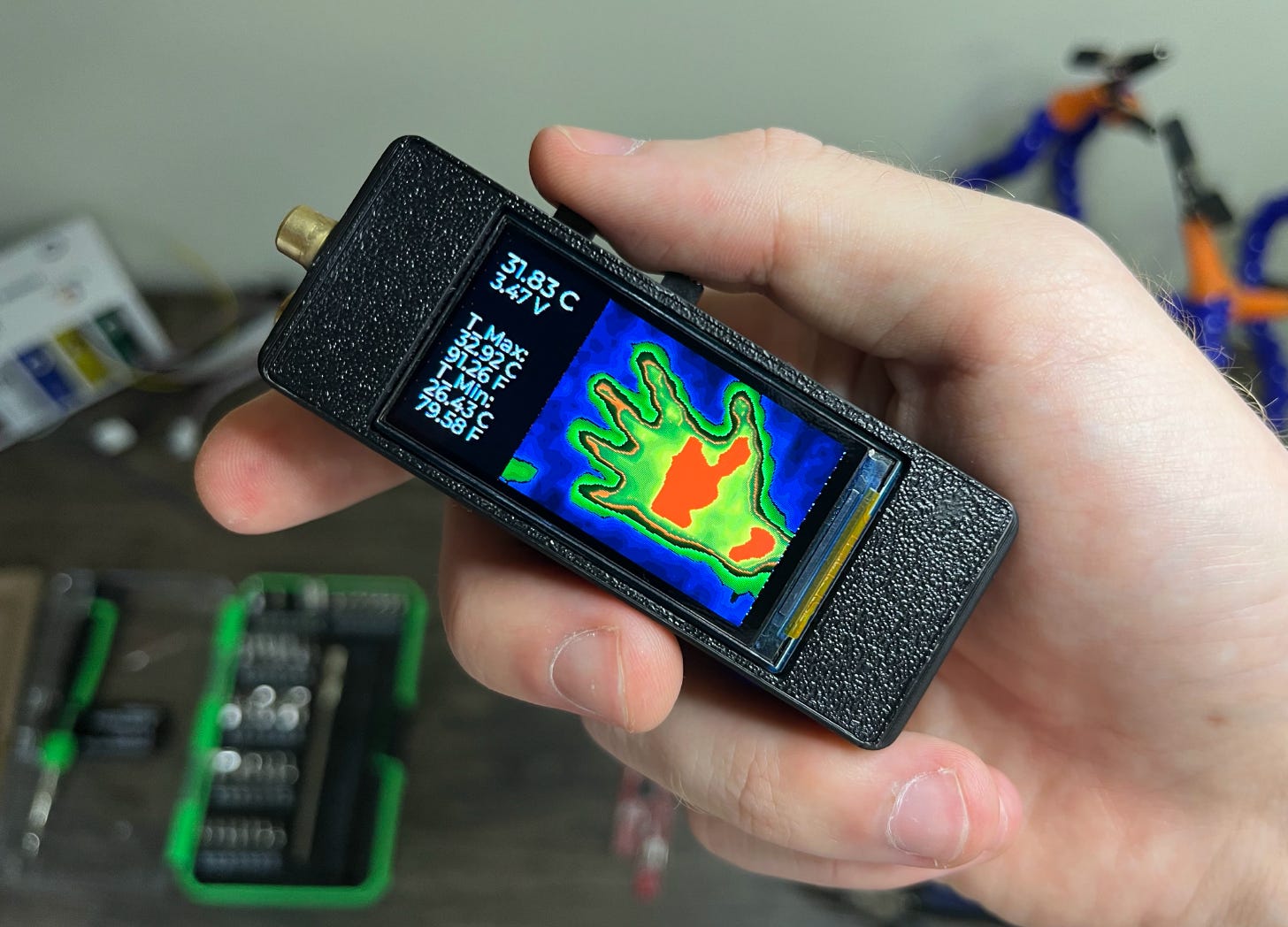
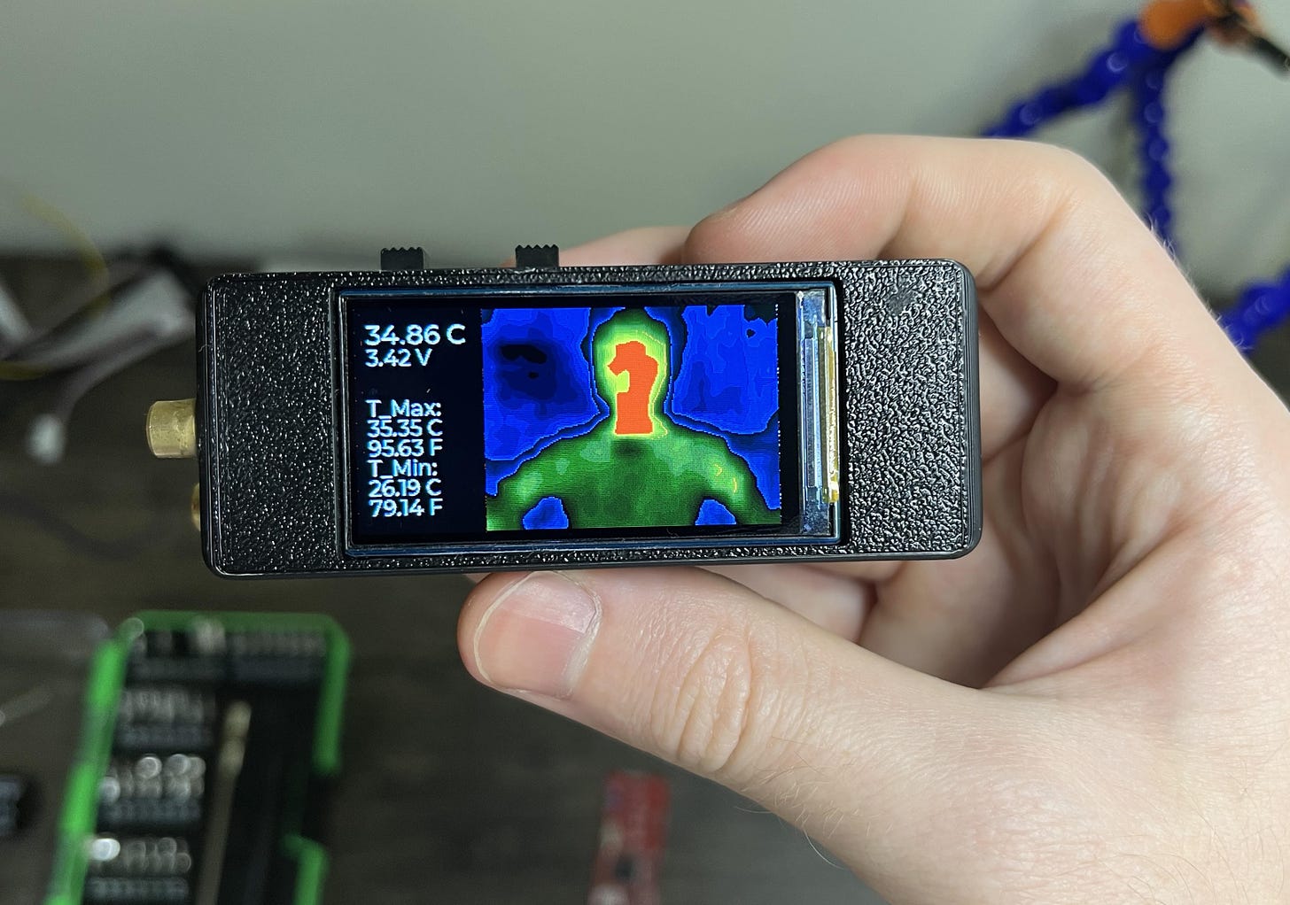
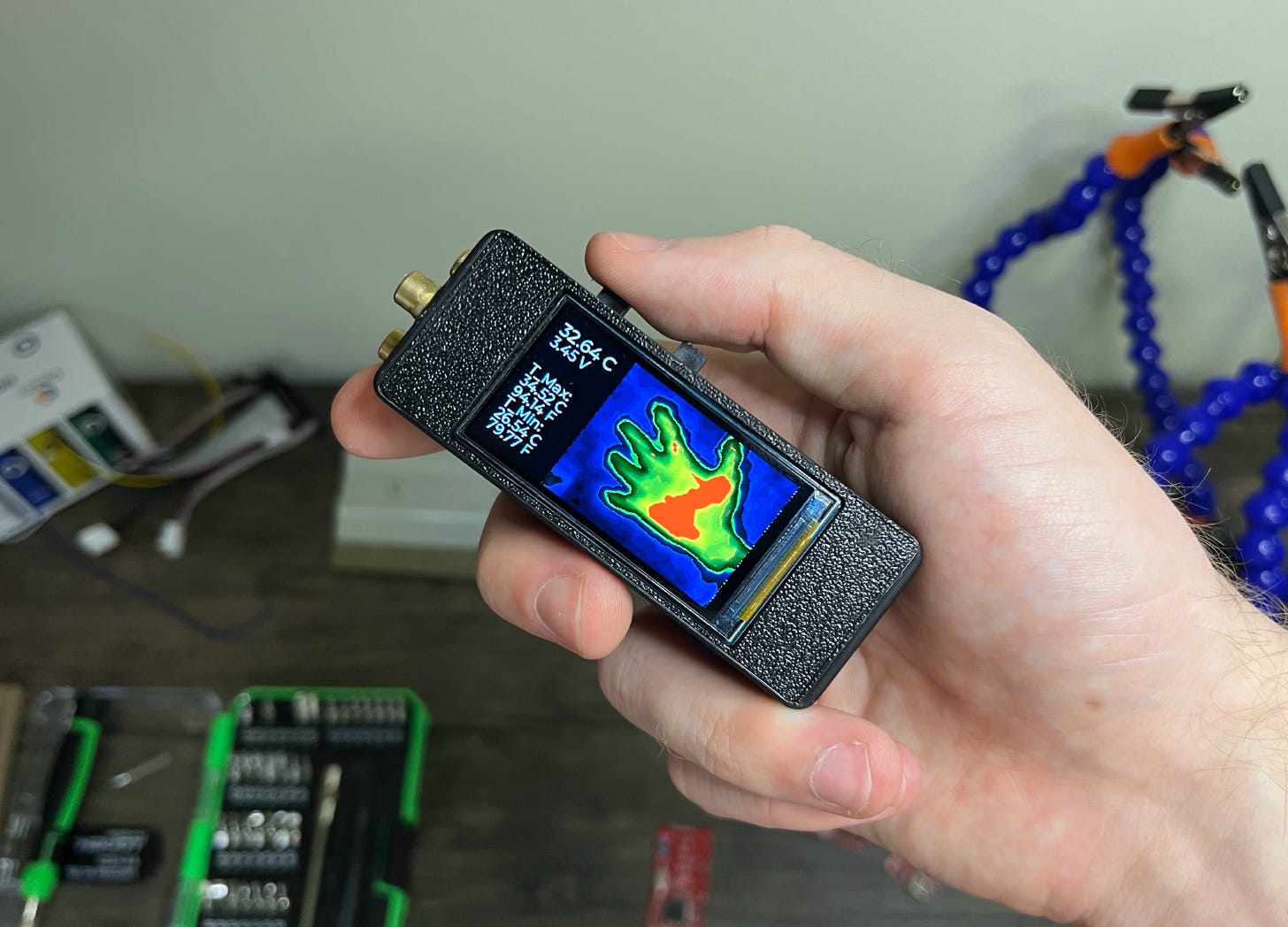
This is my “OpenTemp” project! It is a highly compact, pocket-sized thermal imager/infrared thermometer with a vast measurement range of -40 to 300°C. It is capable of achieving precise infrared radiation measurements corresponding to ±1.5°C (or ±0.2°C up close) in addition to a wide FOV of 110° at 768 FIR pixels of resolution.
Continued..

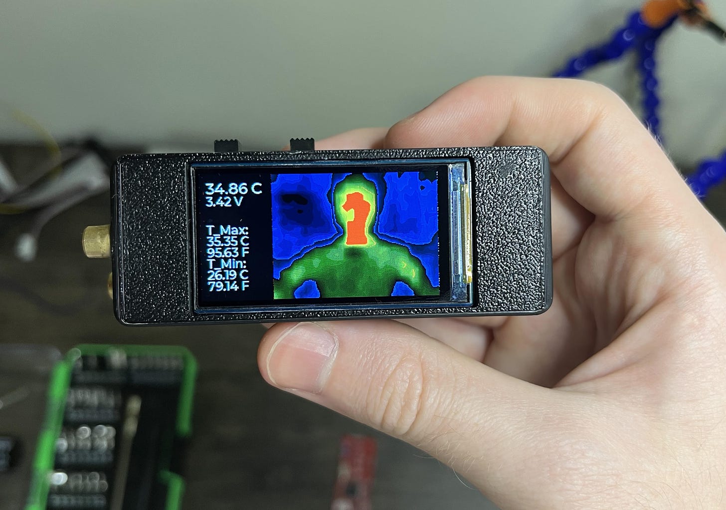
A selfie I took of myself.
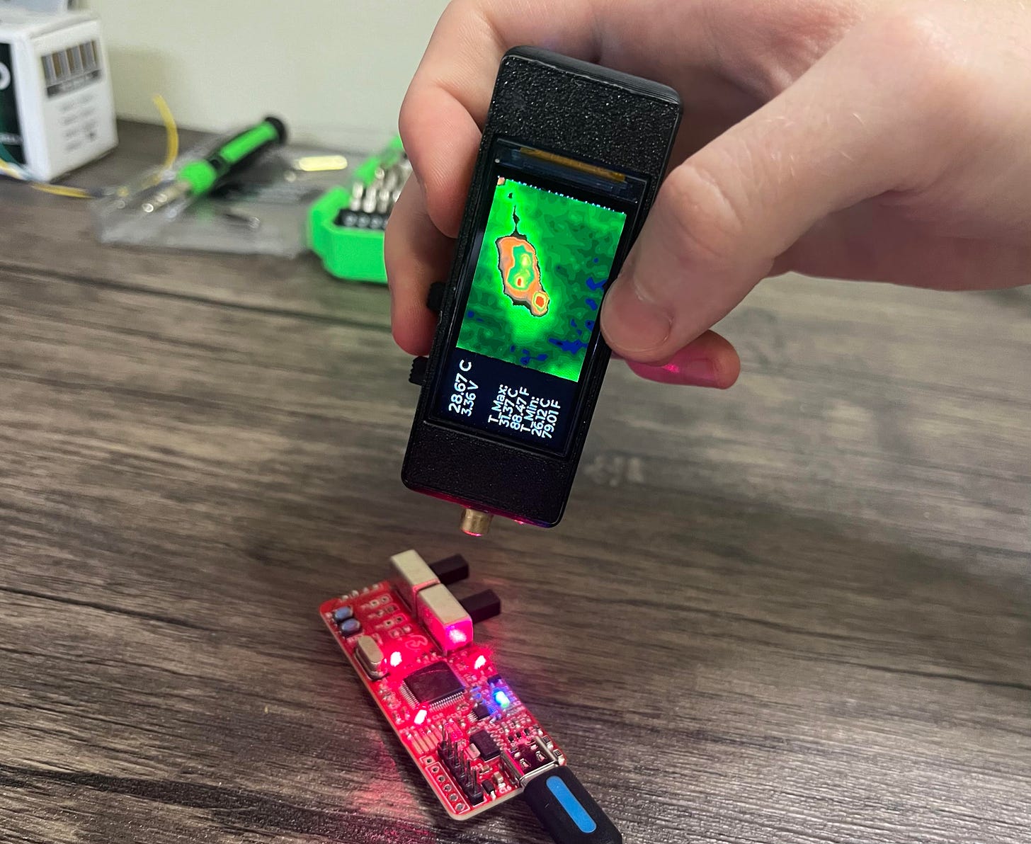
This project can be useful for various applications such as human/animal detection, non-contact temperature measurement, or identifying any places of unusual heating. I have used it multiple times already to help troubleshoot PCBs (excessive heat usually indicates something is wrong), and even check how hot my coffee is without sacrificing tongue cells.
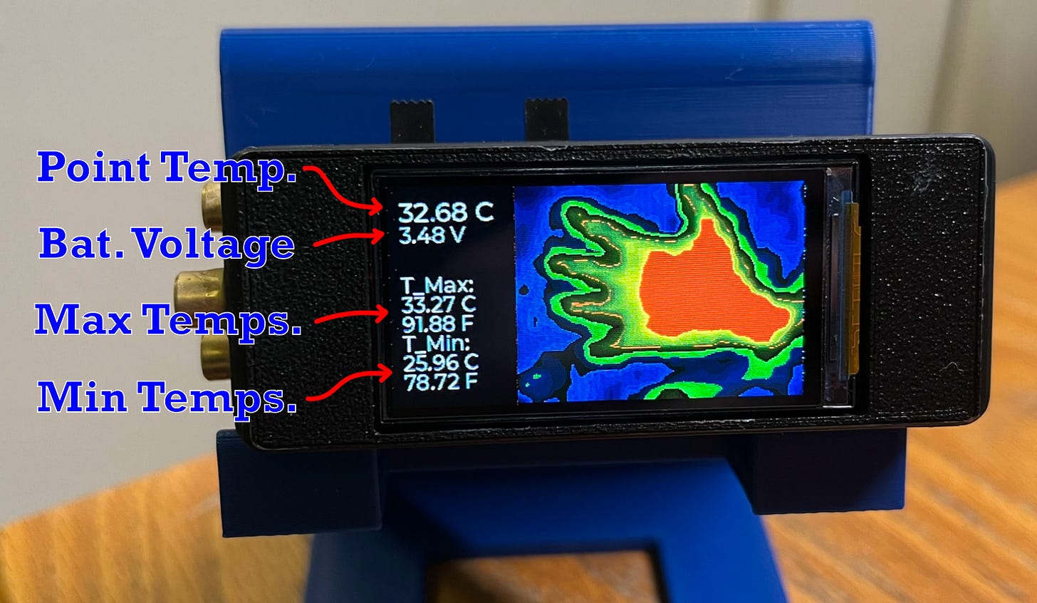
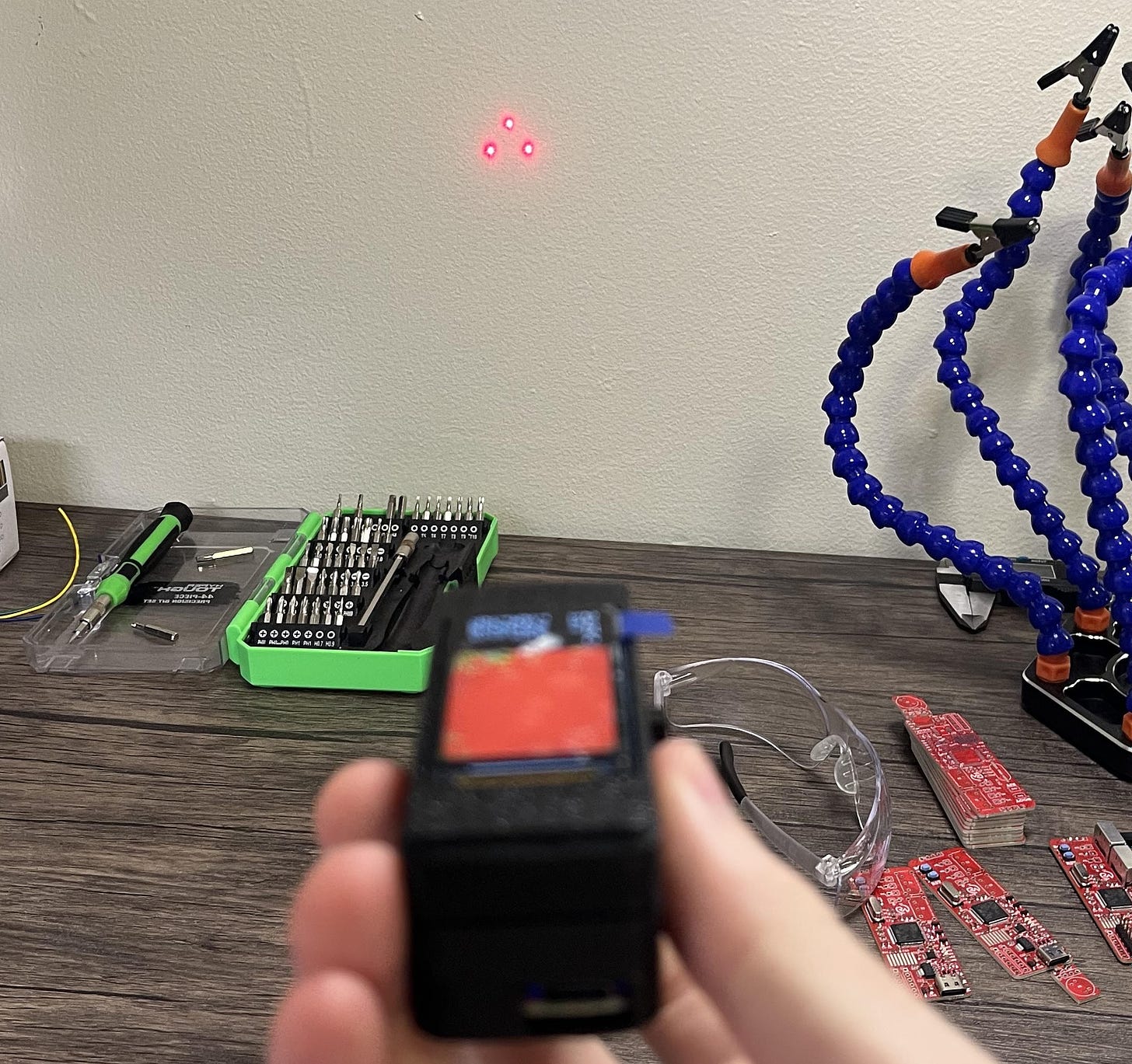
The imager utilizes three “predator” aim-assist lasers to accurately determine the point temperature reading location. At the center of all three dots is an averaged reading of four FIR (Far-Infrared) pixels, which can be useful in precision applications where you only want to know the temperature of a specific area.
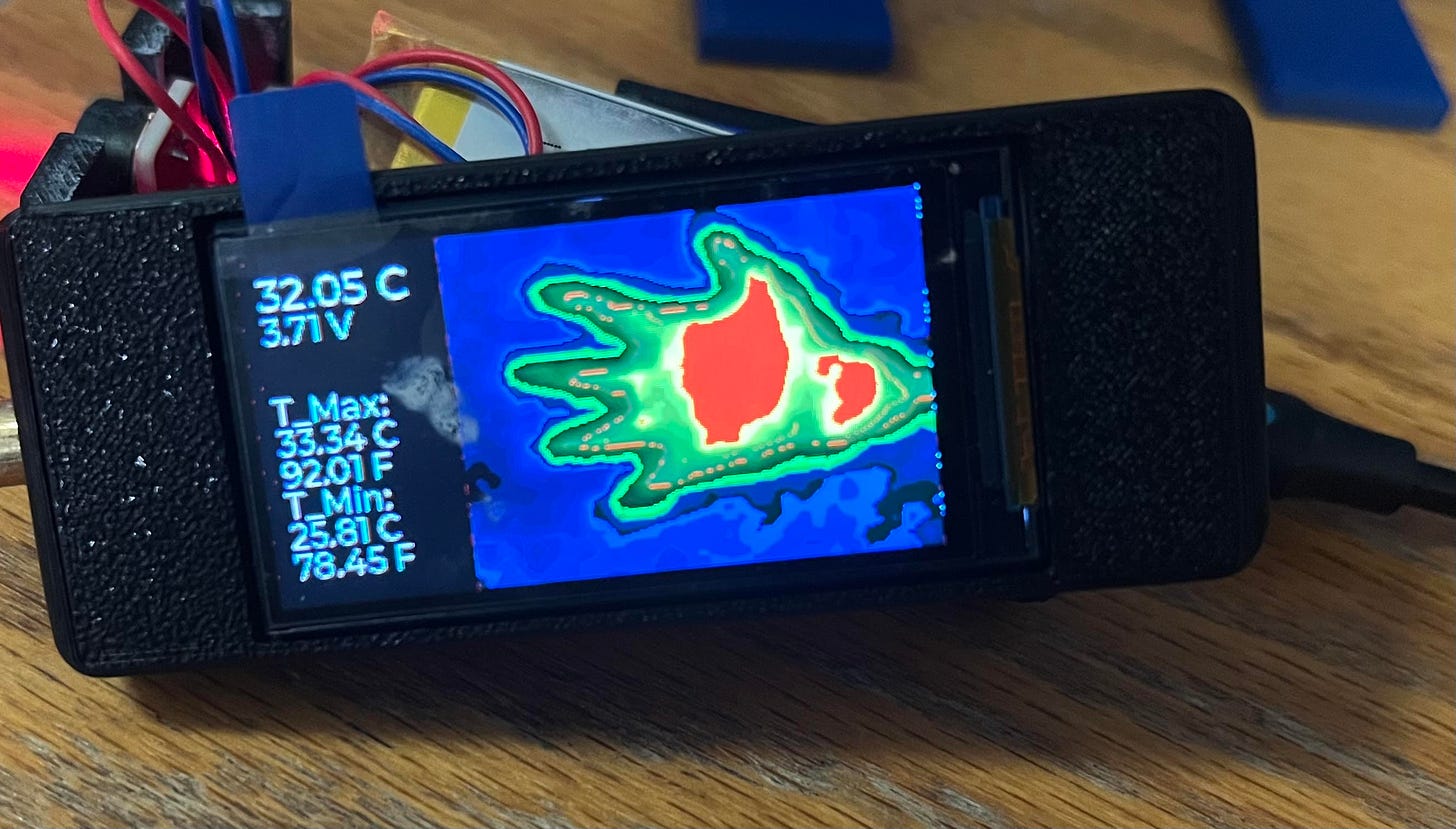
In addition to this, general information is also provided with each scan such as the maximum and minimum detected temperature (converted into degrees Celsius and Fahrenheit), plus the current battery voltage for power monitoring (typically 3.3→4.2V).
When you have the scan you want, you can freeze the screen and readings by flipping the bottom-most switch. This way, you can bring it elsewhere to analyze it more effectively should you need to. This also enables people to use it to take their own forehead temperatures, etc., making it useful in possible medical applications.
Red line.
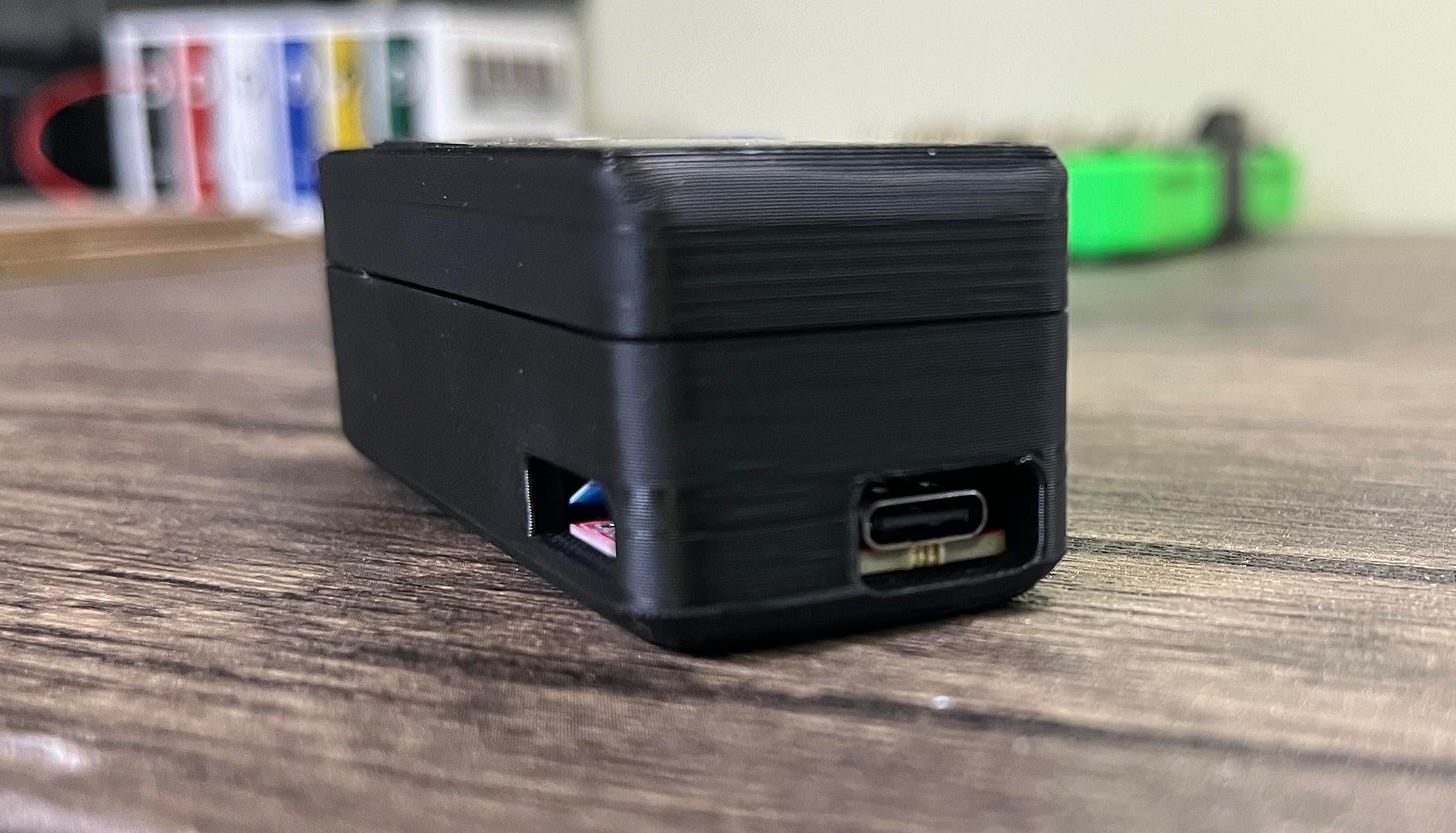
Utilizing a 1000mAh Lithium-ion Polymer battery, it can last for incredibly long periods of time without any need for a charge. However, when the time does come, you can simply plug in any USB-C cable to charge it up in just a couple of hours.
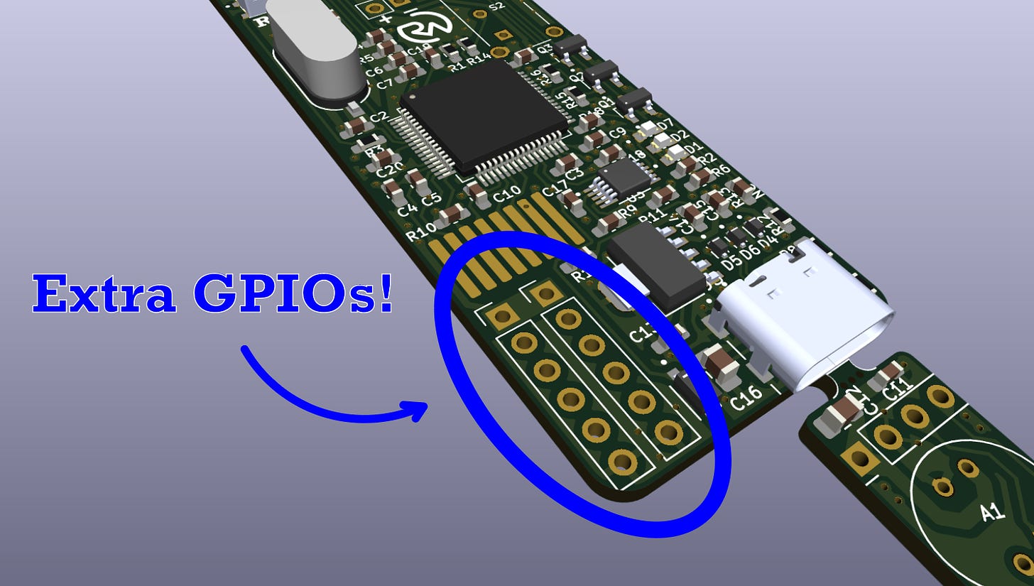
In addition to this, I have broken out numerous GPIO pins so that anyone can feel free to integrate this into their own design. For example, should you decide you want to use this project for human presence detection, simply configure one (or multiple) of the GPIOs to go high on detection and connect the output to your favorite wireless IC for data transmission.
If you enjoy my work, please consider becoming a free or paid subscriber on my homepage. It helps me keep everything open source and is a great way to stay in the loop.
Working Concept
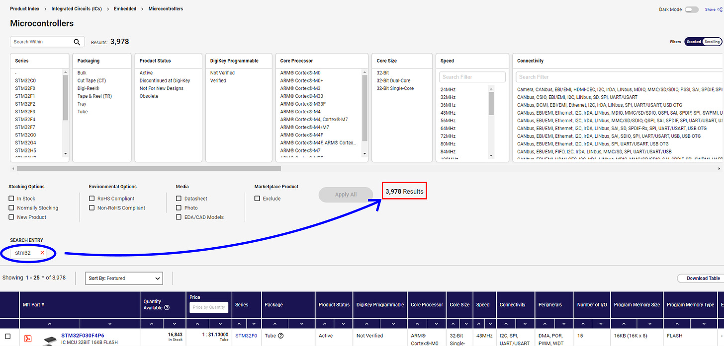
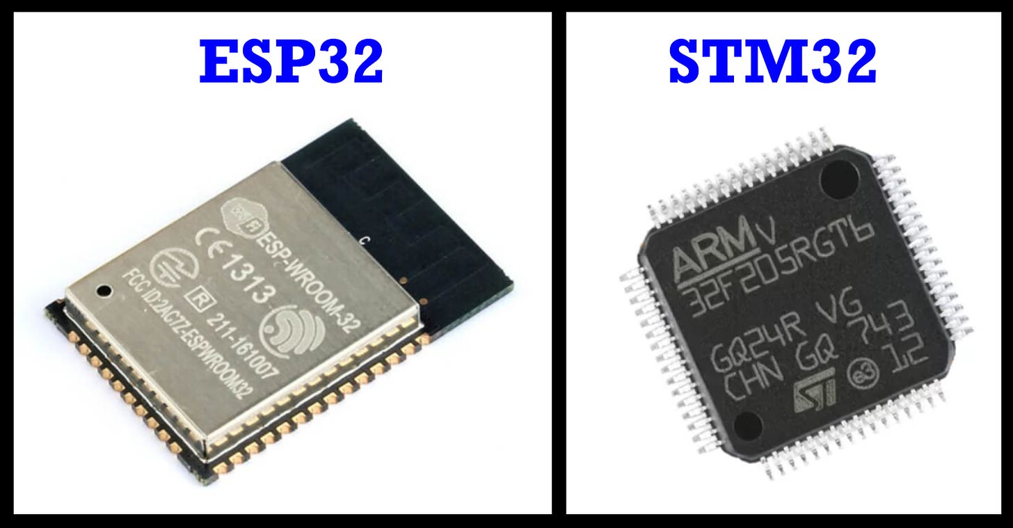
So how does it work? Contrary to many of my other projects, this one does not use an ESP32 microcontroller. Instead, I figured I’d give STM32 a try! Why? Mainly to try something new. ESP32 is fantastic (especially in wireless applications), but STM32s are a popular industry standard with literally thousands of different types (great for various unique applications with specific requirements).
This opens up a lot of different options for further customization, space constraints, processing requirements, etc. STM32 also has a super well-supported graphical development framework that makes it easy to integrate them with various devices, but more on that later!
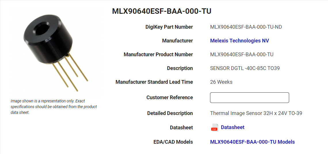
For the thermal imaging itself, I’m using an MLX90640 thermal imager. This is a 24x32 resolution image sensor with the main advantage of good accuracy at a competitive price point ($50). This sounds like a lot, but most imager ICs easily go for hundreds or have a truly terrible resolution (like 4x4px). The MLX90640 is a great compromise!
But how does the MLX90640 work? I couldn’t tell you any black magic, but here are the basics:
- All objects emit infrared radiation, which is associated with their temperature (thermal radiation).
- The hotter an object is, the more infrared radiation it emits in a given time (the wavelength is also shorter).
- The MLX90640 uses an array of thermopiles (tiny temperature sensors) that respond to the given amount of infrared radiation and measure it. Every thermopile (pixel) gets a measurement.
- Each thermopile then converts the infrared radiation it “sees” into a small voltage. This voltage changes based on the intensity of the infrared radiation.
- This value is then digitized and calibrated into a temperature value in °C.
- Now that every pixel is associated with the given temperature that is “sees”, every pixel can come together to create an array of data.
- This array of temperature values can then be mapped to a specified color and displayed as an image.
This is highly simplified but I hope it helps you understand the main idea. If you’d like to learn more, this is a nice article on thermal imagers.
So, I just mentioned that the resolution was only 24x32 pixels. However, the resolution being displayed is much higher than that (168x224). How can this be?
Original (left) vs interpolated (right).
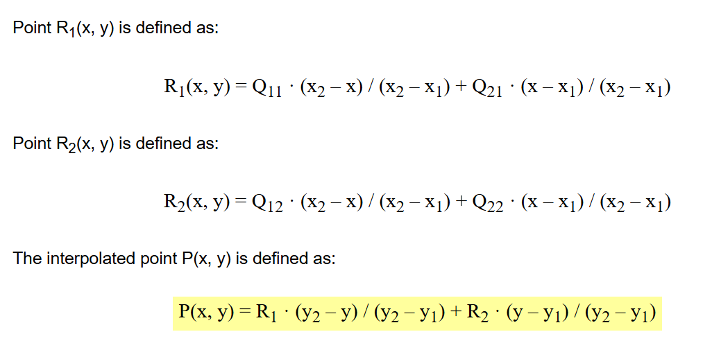
This is done through a bilinear interpolation algorithm. It is a cool math trick that calculates the value of a point based on the values of those around it.
Image: x-engineer.org
Say you don’t know the value of point P, but do know the value of points Q11, Q12, Q22, and Q21. Bilinear interpolation says you can calculate it with two linear interpolations along the x-axis and one along the y-axis.
R1 and R2 are the x-axis interpolations, and the final point P is the y-axis interpolation.
This works in our thermal imager application because we can take the low-resolution points of known temperature data (24x32) and interpolate everything in between to get a higher-resolution (“blended”) image.
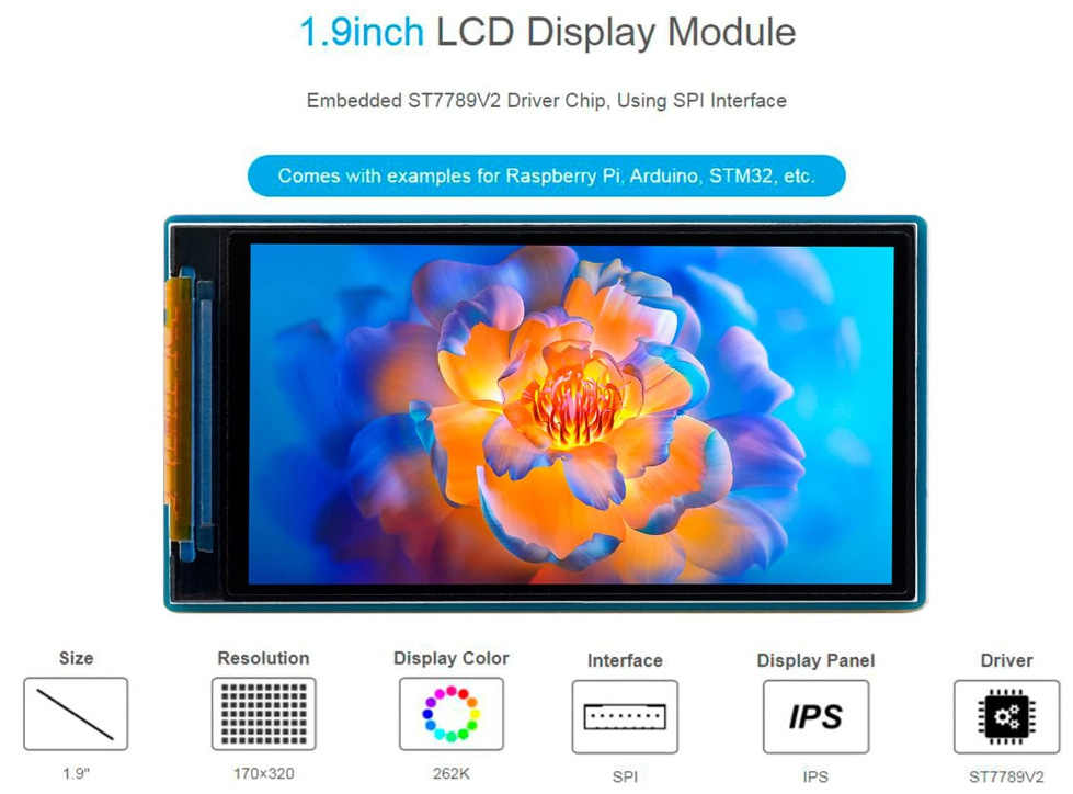
It is technically still 24x32 resolution since no new data is being obtained beyond those points, but it looks far nicer and gives you a much cleaner image. To display all the data, I chose a 170x320 resolution 1.9” 262K IPS LCD driven by an ST7789 via Serial Peripheral Interface (SPI).
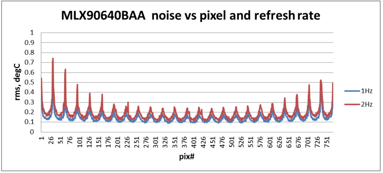
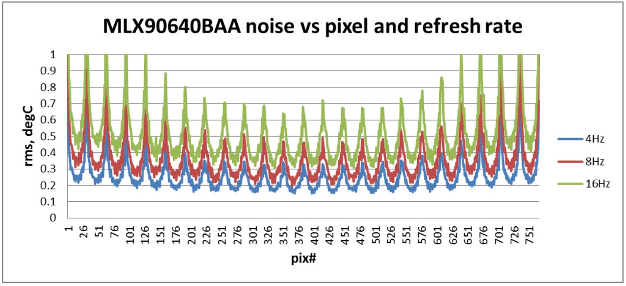
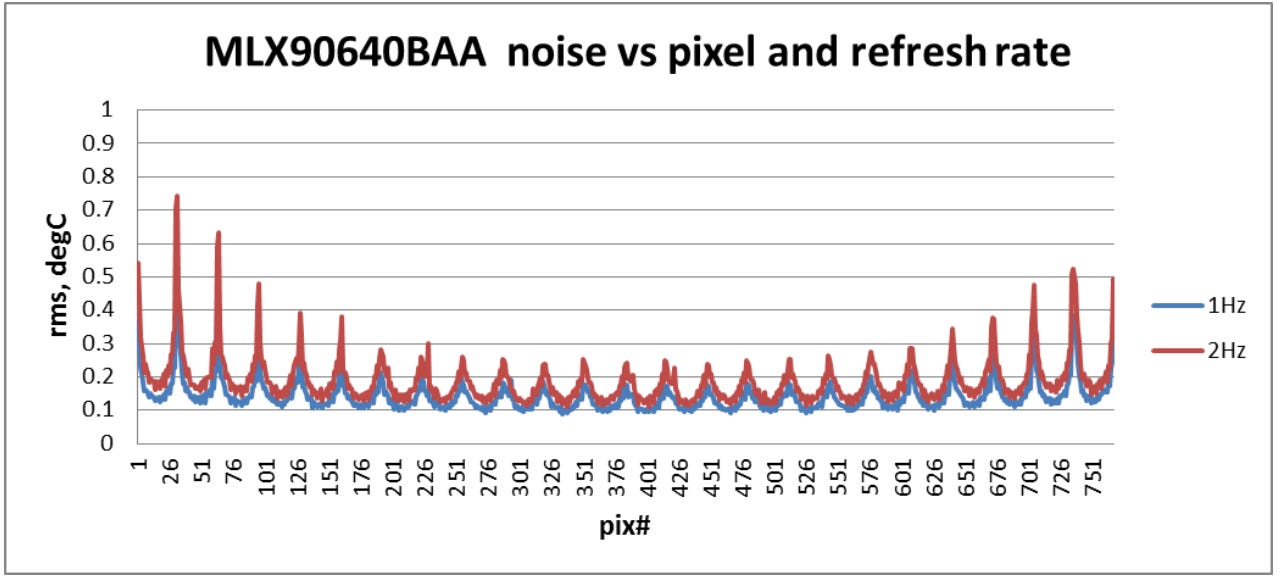
Even when optimized, this is a quite computationally intensive algorithm that yields a slower refresh rate. But that’s okay! This is actually a strength for our application, as a slower refresh rate will allow the MLX90640 to take better measurements for a temperature accuracy of ~±0.2°C.
We are at 2Hz (red line).
While perfect for hardware troubleshooting and situations where accuracy is critical, it may not be ideal if you plan to use this device as a live camera feed. But if that is your intended application, I would probably recommend an STM32H7 with a wireless setup and a higher-resolution camera anyway. This said though, it can certainly still be used for presence detection. What is slow is translating the data to the display, there is no reason why it wouldn’t work to increase the refresh rate to 16Hz and then use something like a digital GPIO/UART to inform your system if an unusual heat signature was detected.
Understanding the Hardware
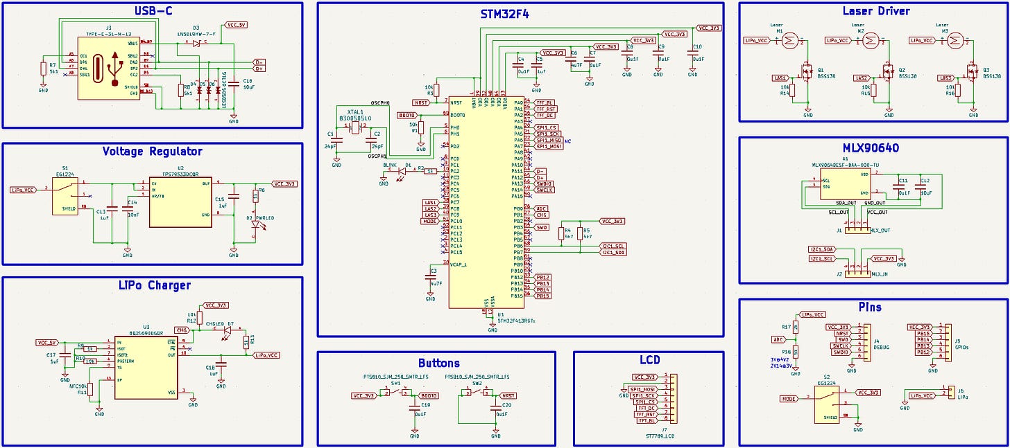
The schematic for this project consists of:
- STM32 microcontroller for signaling, sensor communication, and image processing.
- USB-C port for upload and charging.
- 3.3V voltage regulator to step down the 5V received from USB.
- LiPo charger circuit for safe battery charging and monitoring.
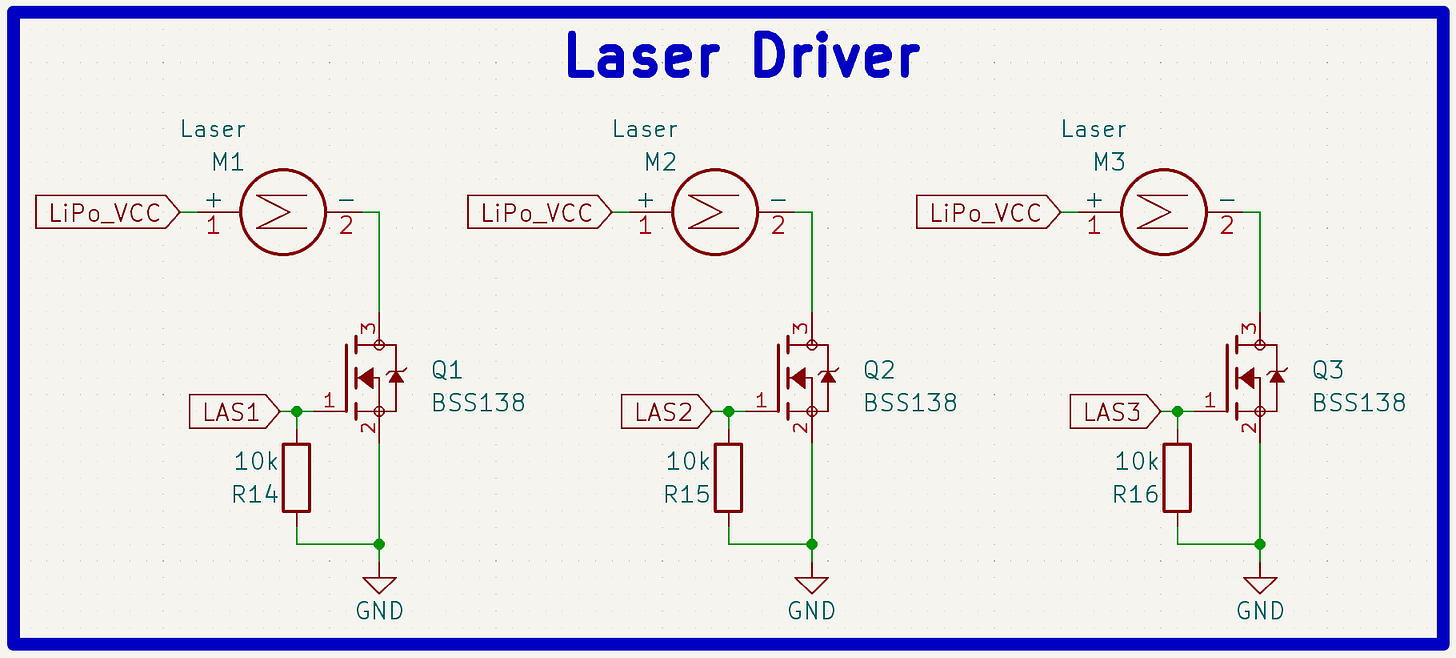
- Three laser drivers (MOSFETs) driven by digital GPIO pins on the STM32.
- LCD (liquid crystal display) and connector for displaying data.
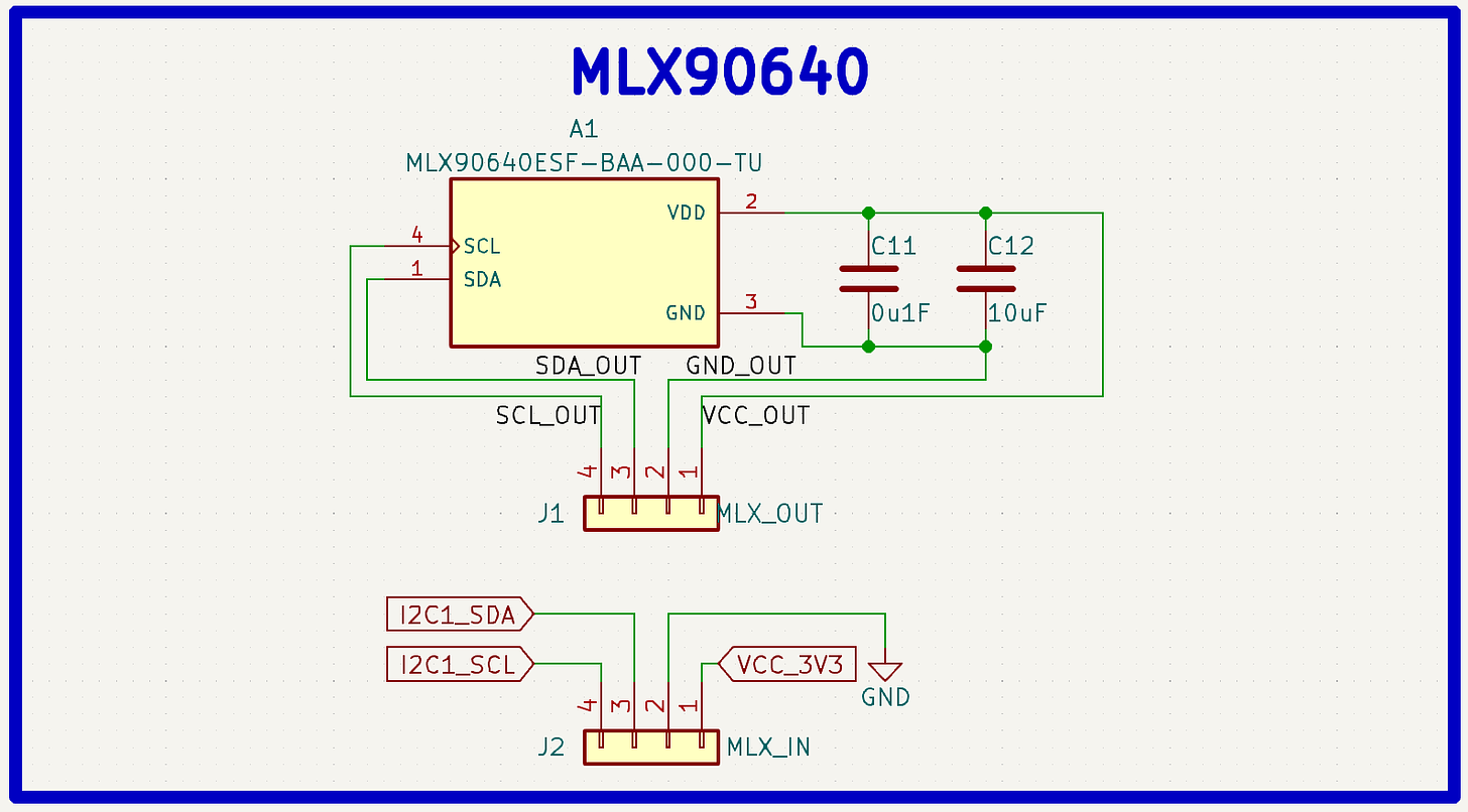
- MLX90640 thermal image sensor and perpendicular connector.
- BOOT and RESET buttons.
Here is the full schematic:
Licensed Under Attribution-NonCommercial-ShareAlike 4.0 International: https://github.com/RoboticWorx/OpenTemp/blob/master/LICENSE.md
Let’s explore it a bit further.
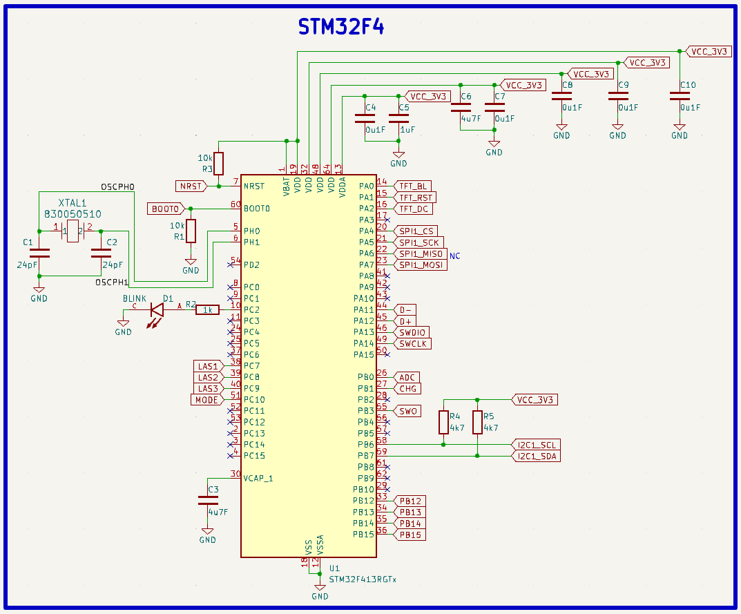
We can look at the STM32F4 portion first.
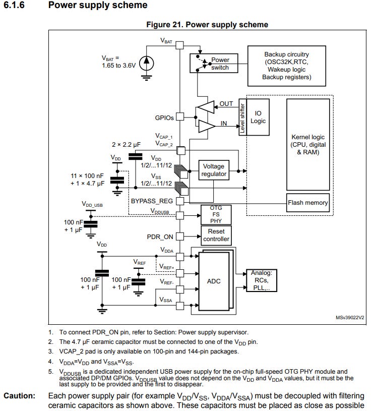
To conceive this circuit, I first looked over the datasheet. After verifying this component would be satisfactory for my application, I went to the datasheet “Contents” and saw the power supply scheme listed under 6.1.6.
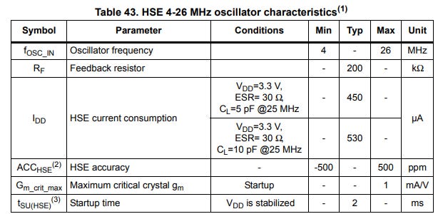
Here it specified how each power supply pin needed to be decoupled (the capacitors), so I just copied them over. After, I went to the HSE (High-Speed External oscillator) section to figure out what crystal I would need to supply the clock signal for the STM32. There it gave me a nice table and some other recommendations, along with a typical application setup.
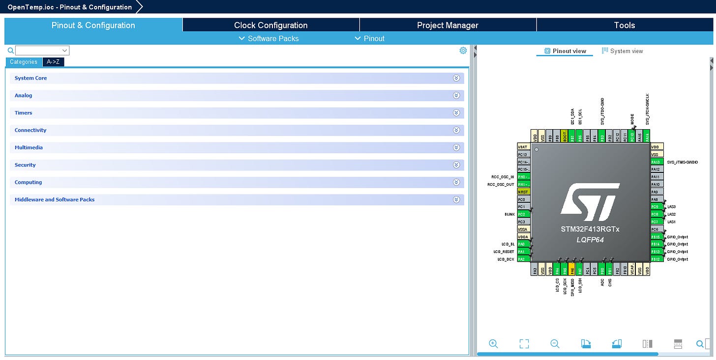
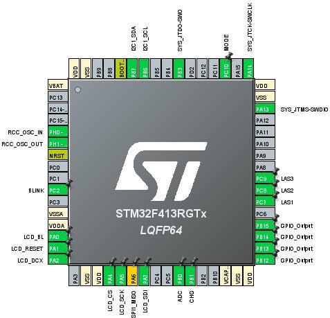
So, I went ahead and picked an 8MHz crystal (between 4-26MHz) and calculated the two load capacitors using this general formula: C=2(CL - Cstray). CL is usually specified in the crystal’s datasheet (load capacitance) and Cstray depends on your layout but can normally be estimated to be around 3pF. Perfect! After that, I just added some pull-up/down resistors wherever a “floating” state would be bad (BOOT and RST pins) and then verified the pins I wanted to use via the STM32CubeIDE programmer (this is the development environment for STM32 MCUs, but don’t worry, it’s not required to flash the firmware for this project if you don’t want to mess with it).
That’s all for the MCU! If you’d like to know more about STM32s, I plan to release a full tutorial soon on the different types in addition to setting up and understanding the programming environment (similar to the one I did on ESP32s). If that interests you, please consider subscribing to the newsletter or even becoming a paid subscriber on my homepage. I could really use the support.
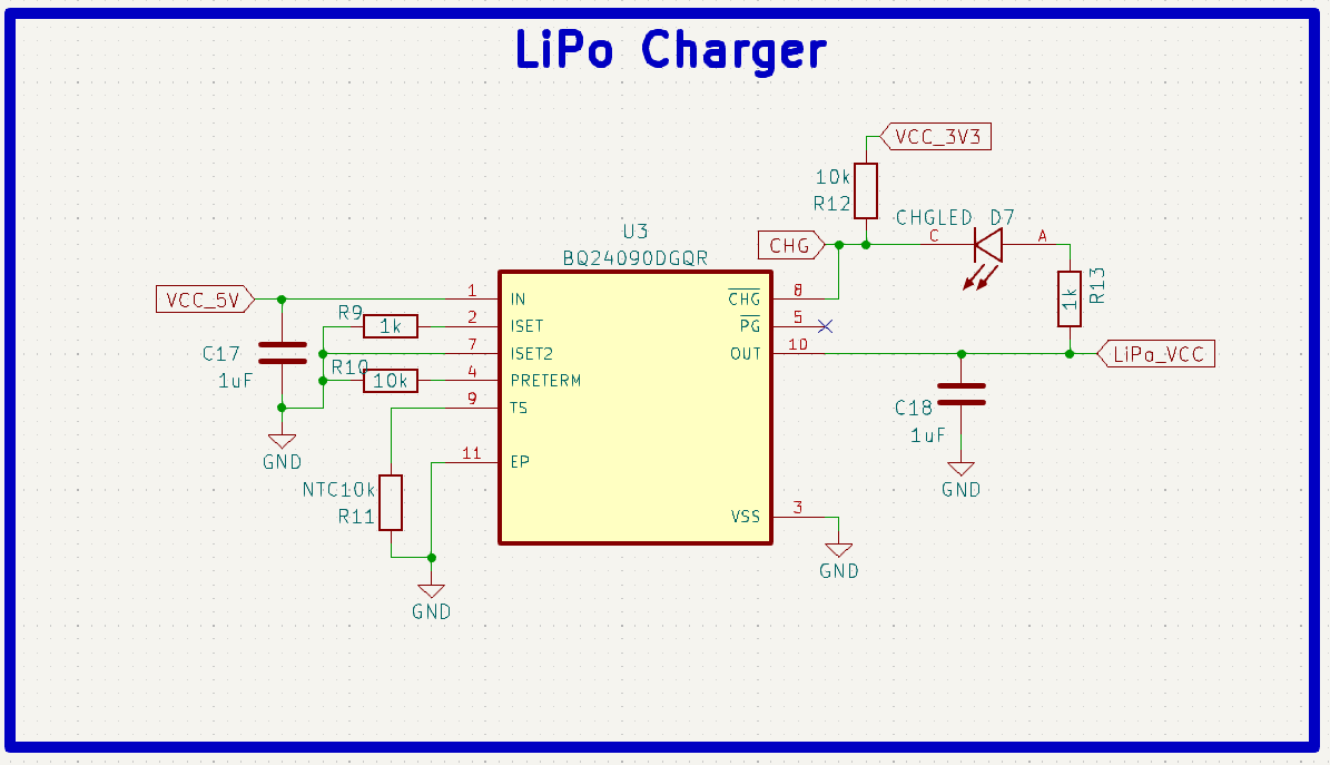
Now let’s go through the LiPo charger circuit.
For this, I’m using the BQ24090DGQR, which I’ve also used in my other projects. This schematic uses the same standard decoupling caps C17 and C18 but with some extra resistors, R9 and R10 to set charge termination and speed. I ended up not connecting R13 to preserve power consumption (one less LED) but you can add it if you would like. The value of that resistor will determine LED brightness (higher resistance → less bright). R9 is used to pull up the opposing side to ensure the charging LED only turns on when the CHG pin is pulled low. If for any reason the LED is slightly on when it’s not charging, feel free to decrease the pull-up value to get a stronger pull. I also connected this pin to the microcontroller for monitoring.
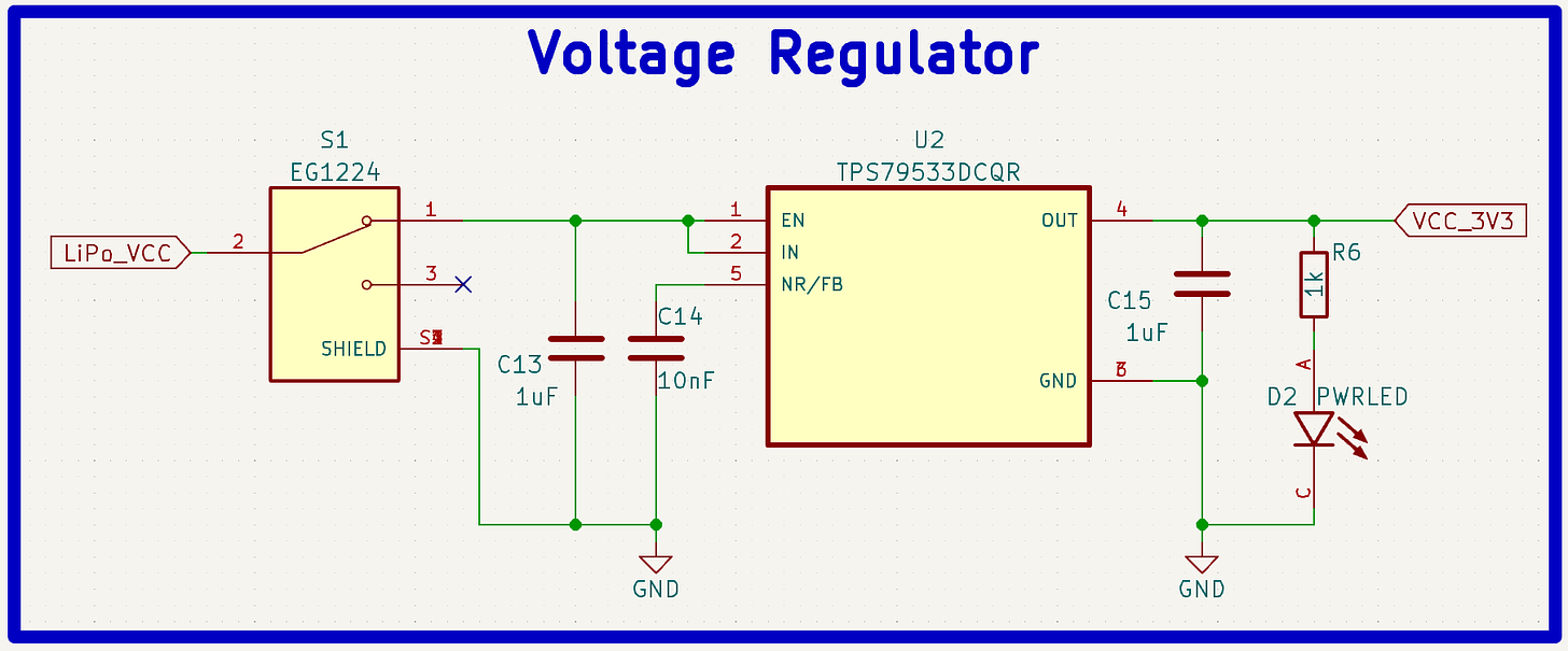
There’s not a whole lot to the voltage regulator circuit, just a few decoupling capacitors recommended by the datasheet and a power switch to turn everything off when not in use.
For the laser driver, similar to my smartwatch project, I just used a few N-channel MOSFETs (digital switches) to turn on and off each laser based on the state of the “LAS” gate pin set from the microcontroller. To make sure they are off when not being actively driven, some 10k pull-down resistors are also included.
Now finally the MLX90640 circuit! Luckily, Melexis (the company that makes the MLX90640) made interfacing with it pretty easy and only recommends a couple of decoupling capacitors. Nice! Then I just added an extra connector so that I could attach it perpendicular to the PCB (for aiming).
That’s all!
Building the Board
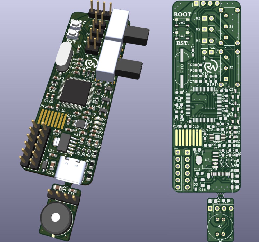
On to assembling the PCB (Printed Circuit Board)!
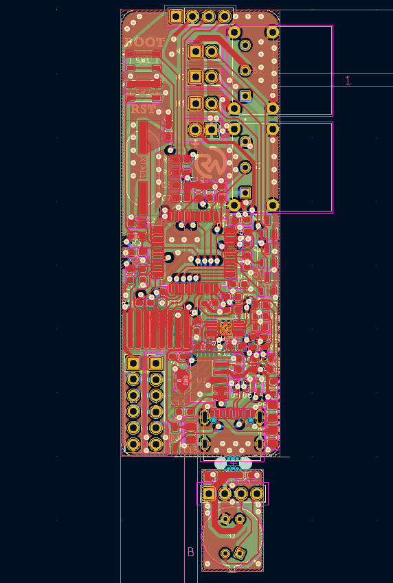
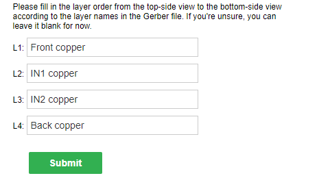
This is a 4-layer board that I made in KiCad. The stack-up I used was a signal top layer, two ground planes, and a power/signal bottom layer. With the two ground planes in the middle, the signal/power layers have somewhere to “couple” to which gives them better signal integrity.
- The Gerber/fabrication file for the board can be found here.
- Editable KiCad PCB files are available here to paid subscribers. Want to become a paid subscriber? It’s only $5 and I would really appreciate your support!
- The part list for the PCB can be found here with the placement sheet available here.
- As always, I know that it can seem like a pain to have to order parts but it’s really not so bad as almost all the parts you order from one project get reused. Think about how much you’ll learn with some hands-on experience!
If you’re interested in learning more about embedded systems, check out Robert Feranec and Phil’s Lab on YouTube. They’re great designers and I’ve learned a lot from them. I also explained a lot about how I route my PCBs in my ESP32 article.
Now all we need to do is get the board made. A perfect job for my go-to PCB manufacturer, PCBWay!
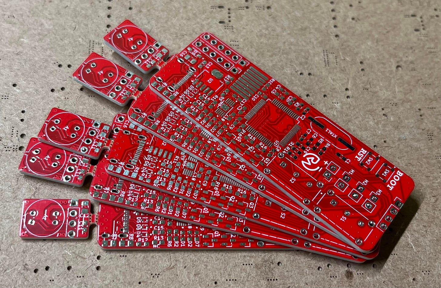
I never have to worry about their PCB quality, in addition to their other services such as 3D printing and CNC machining. PCBWay also features nine different solder mask colors to choose from and three different silkscreens which is great for customization. (I even believe they have multi-color solder masks now!) I chose mine to be red (since it is a PCB that will measure heat), but you can feel free to choose yours to be whichever color you’d like!
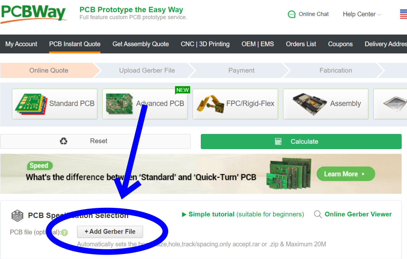
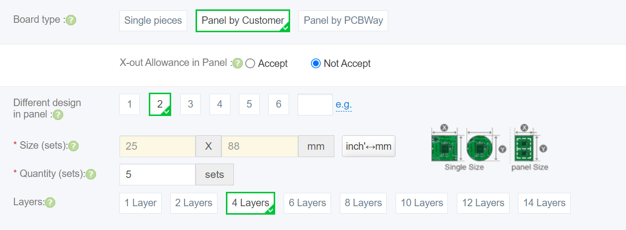
Since I designed with KiCad, I didn't even have to leave my design software to check out thanks to their convenient plug-in! If not though, you can always just go to PCBWay.com, click on quick-order PCB, and upload the Gerber file for the board. Or alternatively, just go here which I have saved in my favorites bar. I recommend clicking the stencil option at checkout to save some headaches!
If you’re asked about the stack-up, you can just fill it out like so:
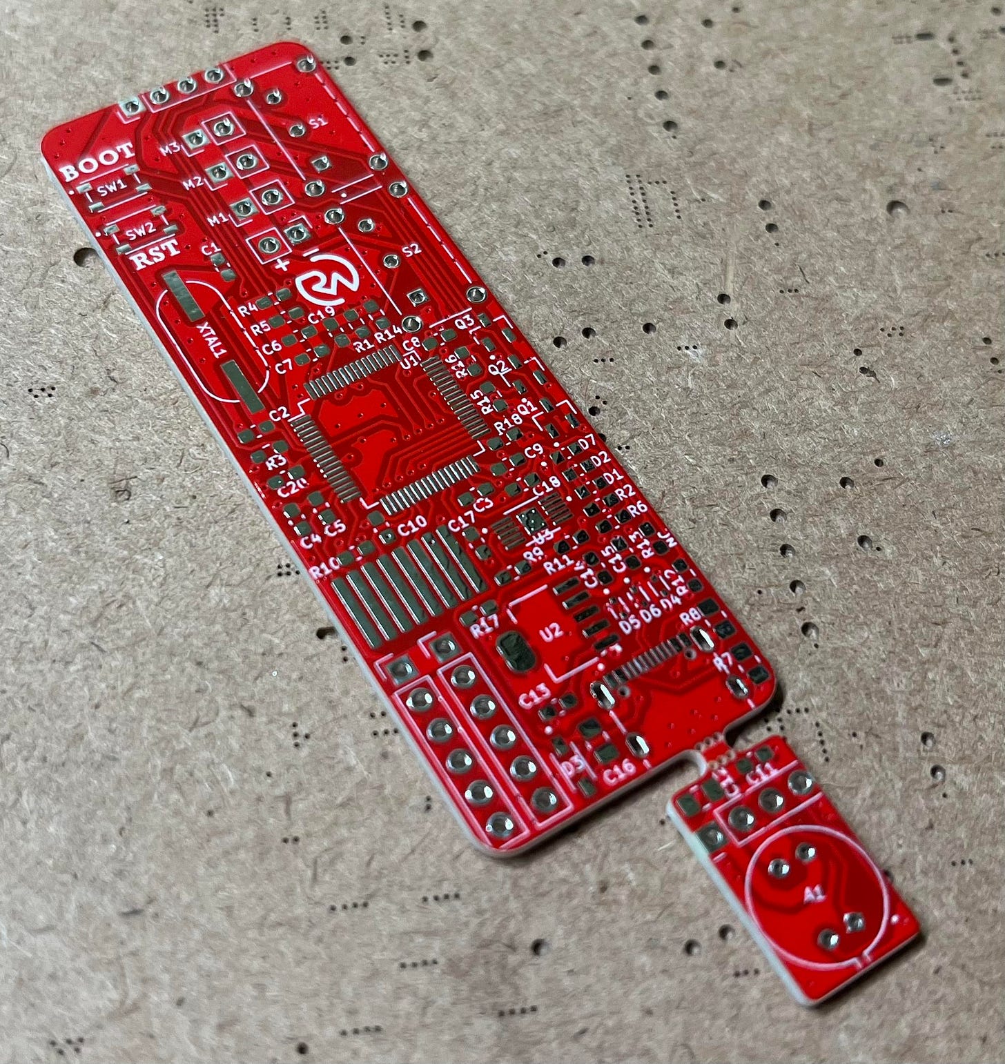
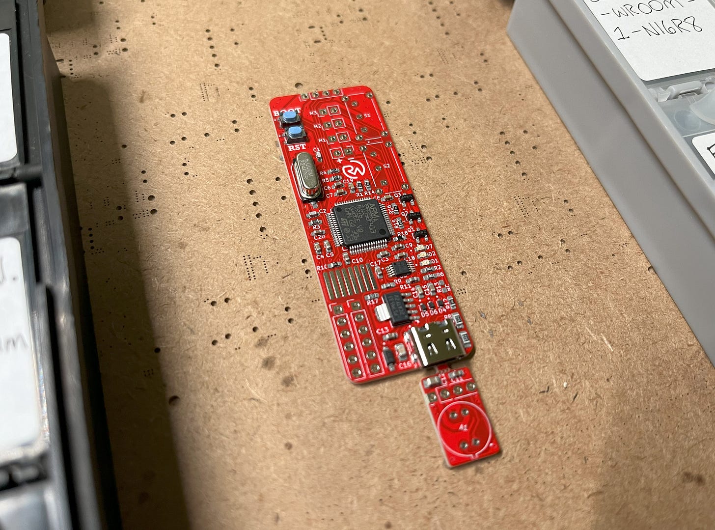
As always, the PCBs looked incredible when I got them a few days later!
Let’s assemble them!
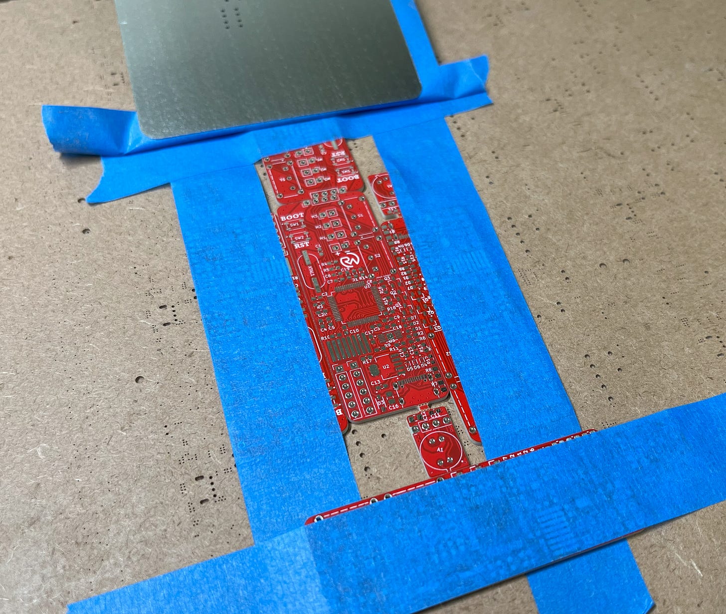
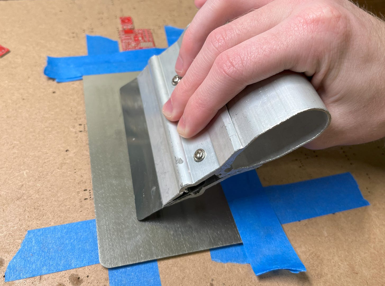
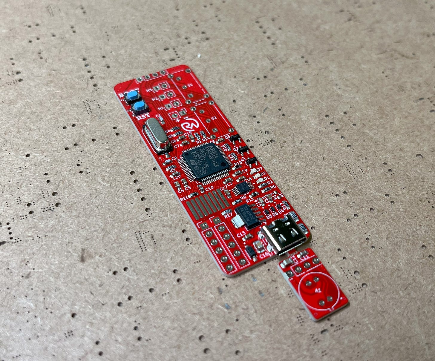
The reference/placement sheet for the PCB can be found here. First, tape the PCB down and apply solder paste using the stencil.
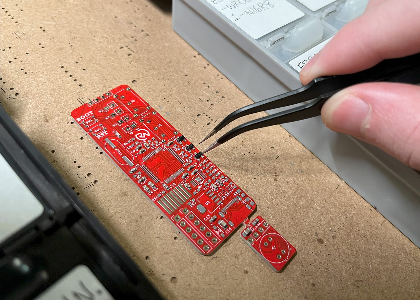
With a layer of solder paste over the pads, you can then begin placing the various components in collaboration with the reference sheet.
Perfection!
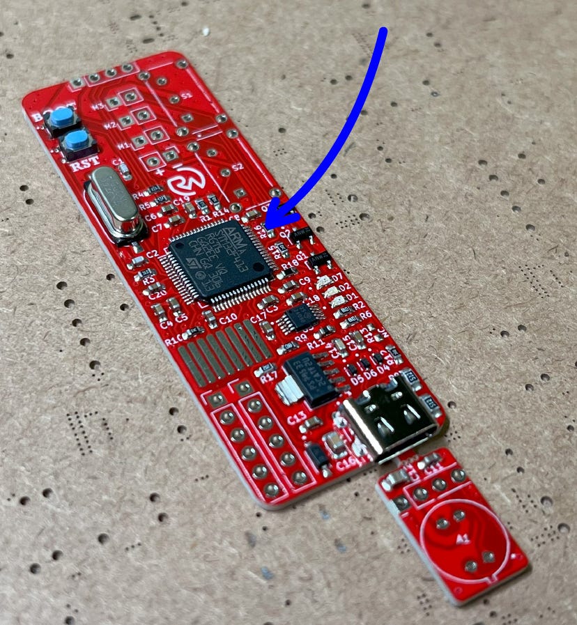
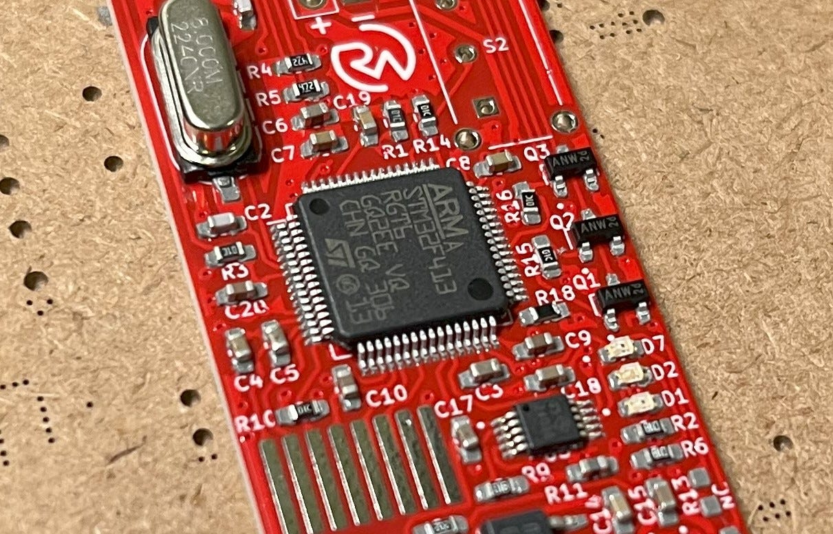
As an important note: The STM32F4 needs to be placed with the orientation below! Pin 1 is marked with a small concave hole and does not line up with the text orientation. I had to learn this the hard way (many hours of troubleshooting why it won’t work haha).
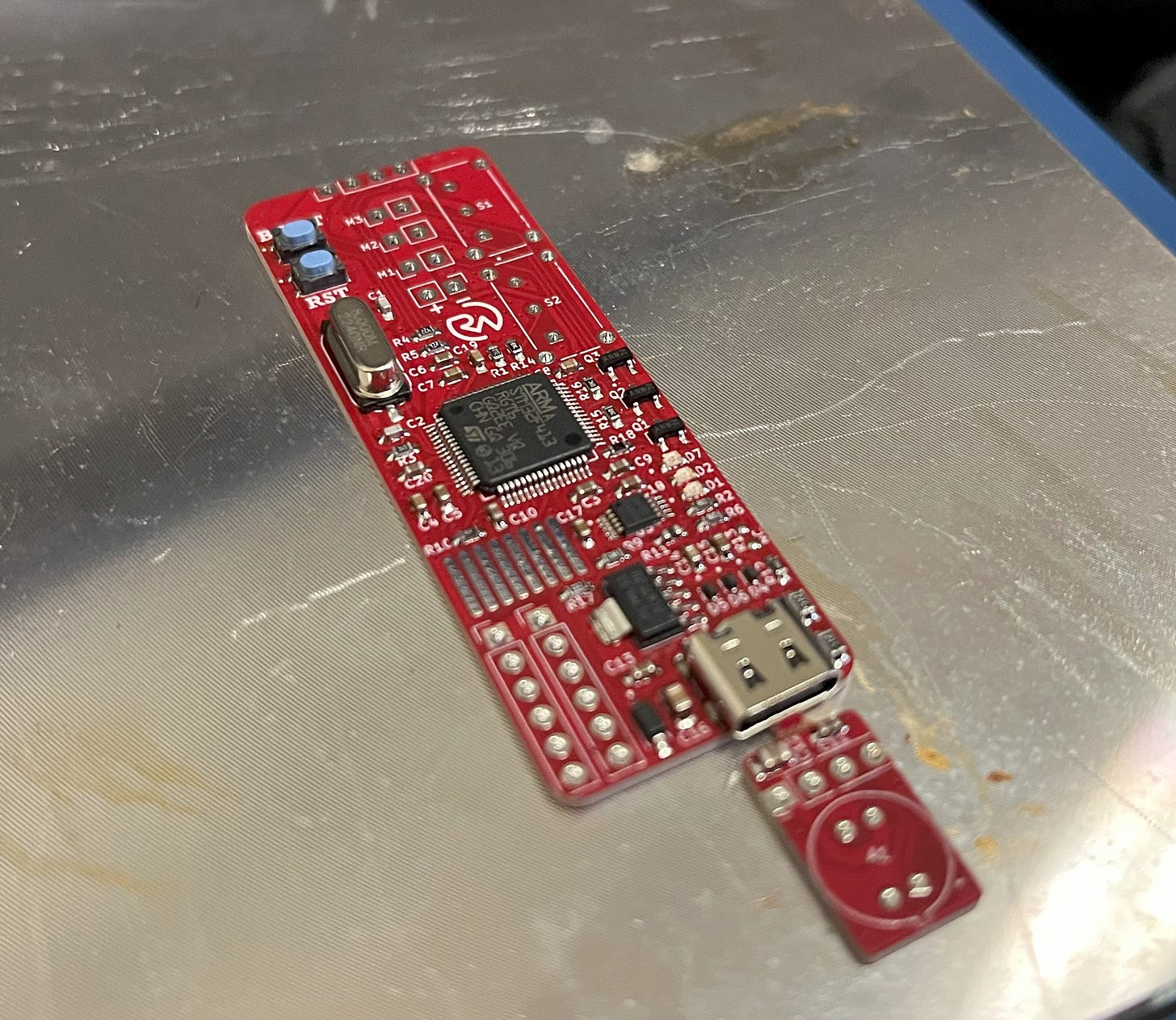
After that, gently place the PCB on your hotplate and turn it on to melt the solder paste.
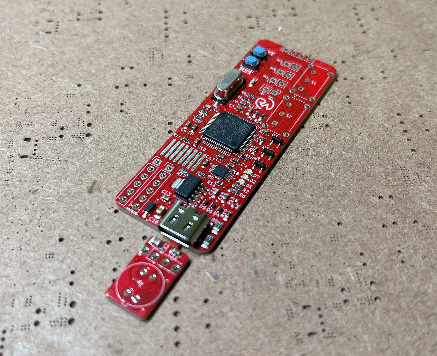
That’s it! Pretty.
Assembly
This section will go over how to assemble the rest of the project.
The logo-ed STL 3D printer files can be found here for free on my Thingiverse!
If you’re interested in also obtaining the logo-less STL files and the editable STEP file, please consider becoming a paid subscriber! I don’t use ads, so I rely on your support! Plus, it’s only $5 and you will receive the following benefits. Already a paid subscriber? Access your materials here!
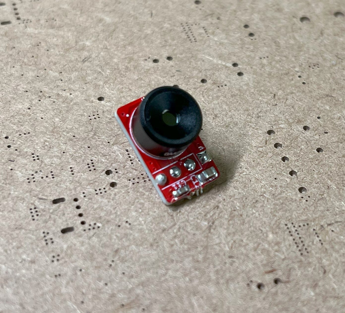
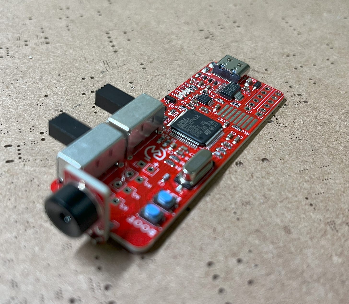
First, take your finished PCB and break off the piece with mouse bites. Then insert the MLX90640 and solder it in.
Make sure the little notch on the top lines up with the mark on the silkscreen!
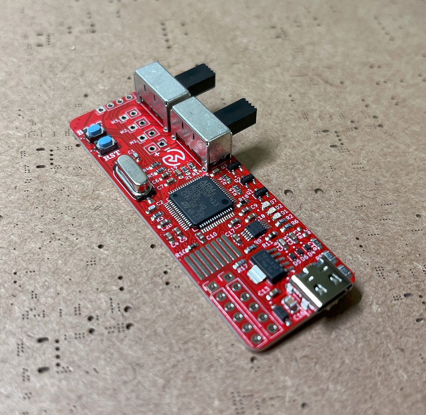
After that, you can push in and solder on the EG1224 switches.
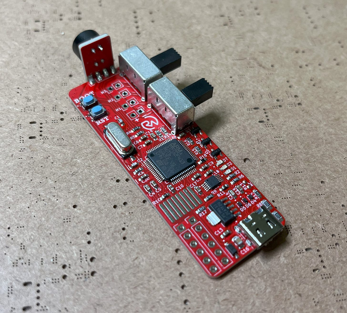
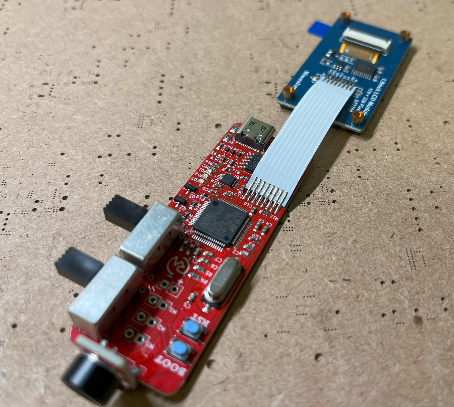
With that, solder on the camera piece you just connected the MLX90640 to. To do this, I recommend pre-soldering the pins and then simply bridging them with your iron to connect the two. Also, do your best to make the camera perpendicular to the PCB.
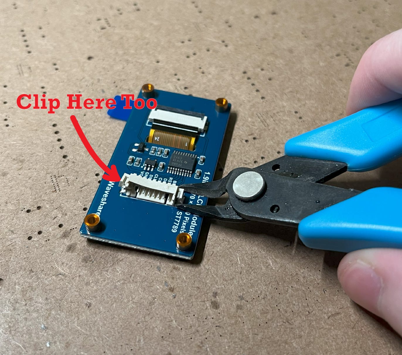
Nice! With that, grab the LCD display and go ahead and clip both sides of the pin connector.
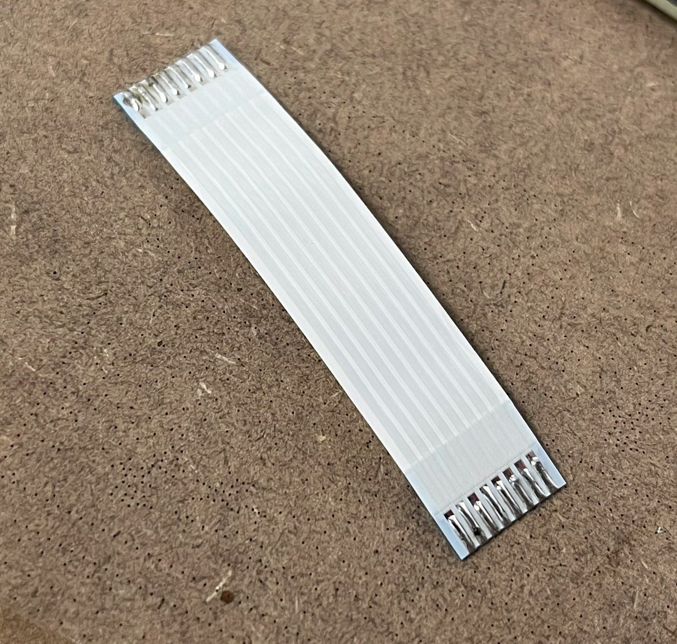
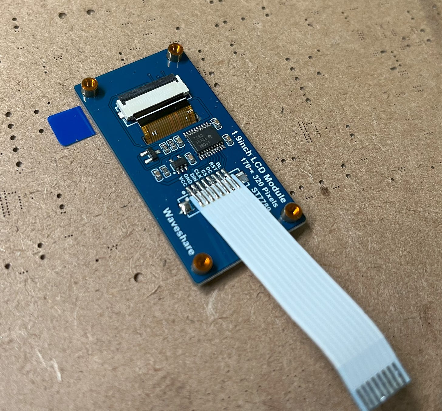
Then use a hot air gun or similar to remove the rest of the connector. After pre-soldering the FFC connector some, you can then bridge it onto the display.
With that, you can do the same to connect it to the PCB.
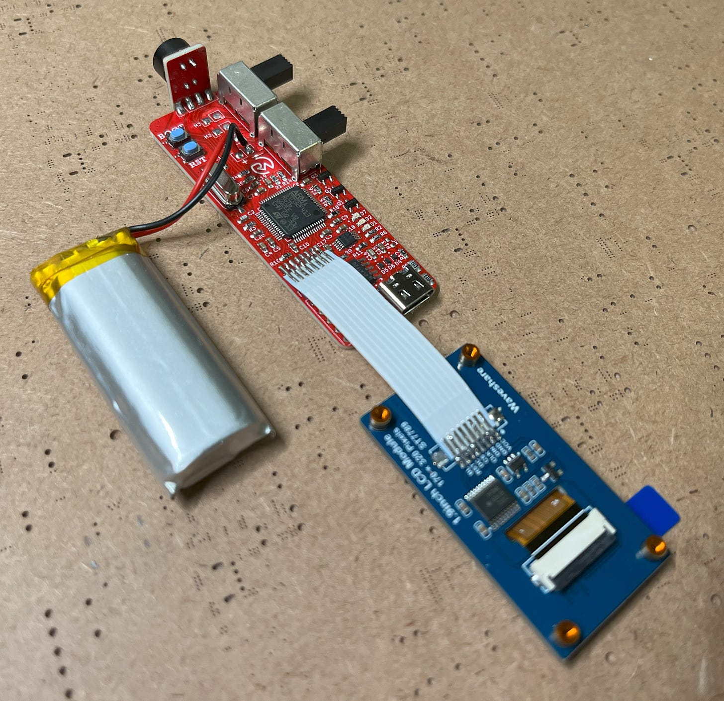
Excellent! This is a good time to go ahead and plug in the board to your computer and upload the program via USB to make sure everything is working. If all goes well, the LCD should be displaying neat temperature data afterward. Instructions to do this can be found in the programming section here. Don’t worry, it’s super simple! (Side note: Make sure the power switch is on when testing.)
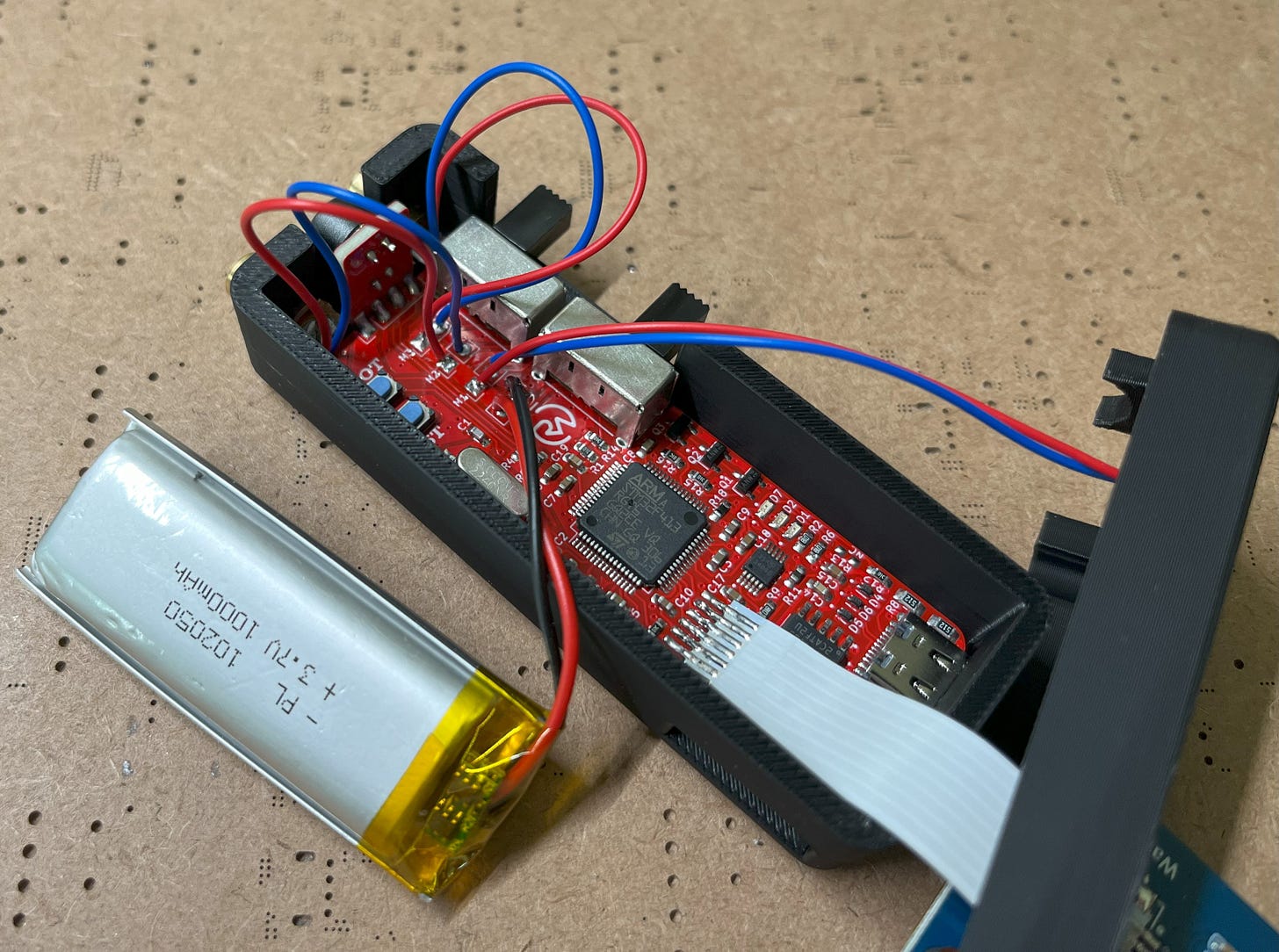
After that, go ahead and connect the LiPo battery. The anode (positive) is on the left!
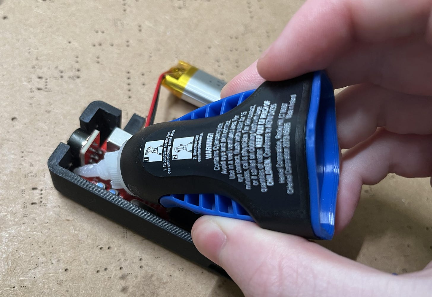
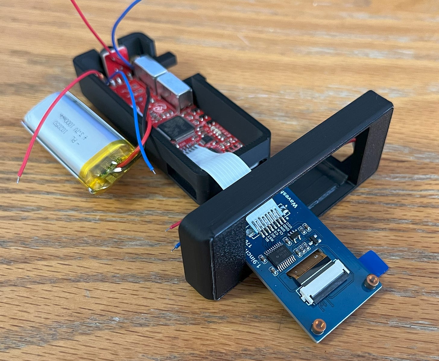
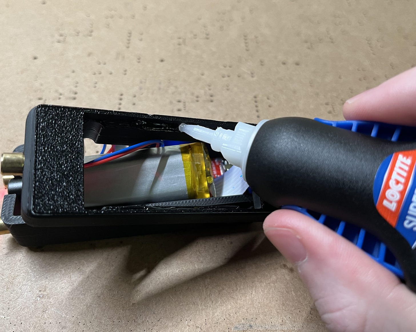
You can now go ahead and glue down the PCB into the bottom piece of the 3D-printed case. After it’s secured and the glue has dried, put some more glue down on the bottom and push the two bottom laser modules through. It should be a bit tight, but this is intentional.
Then, do the same thing for the top piece of the casing.
Next, slide the LCD through.
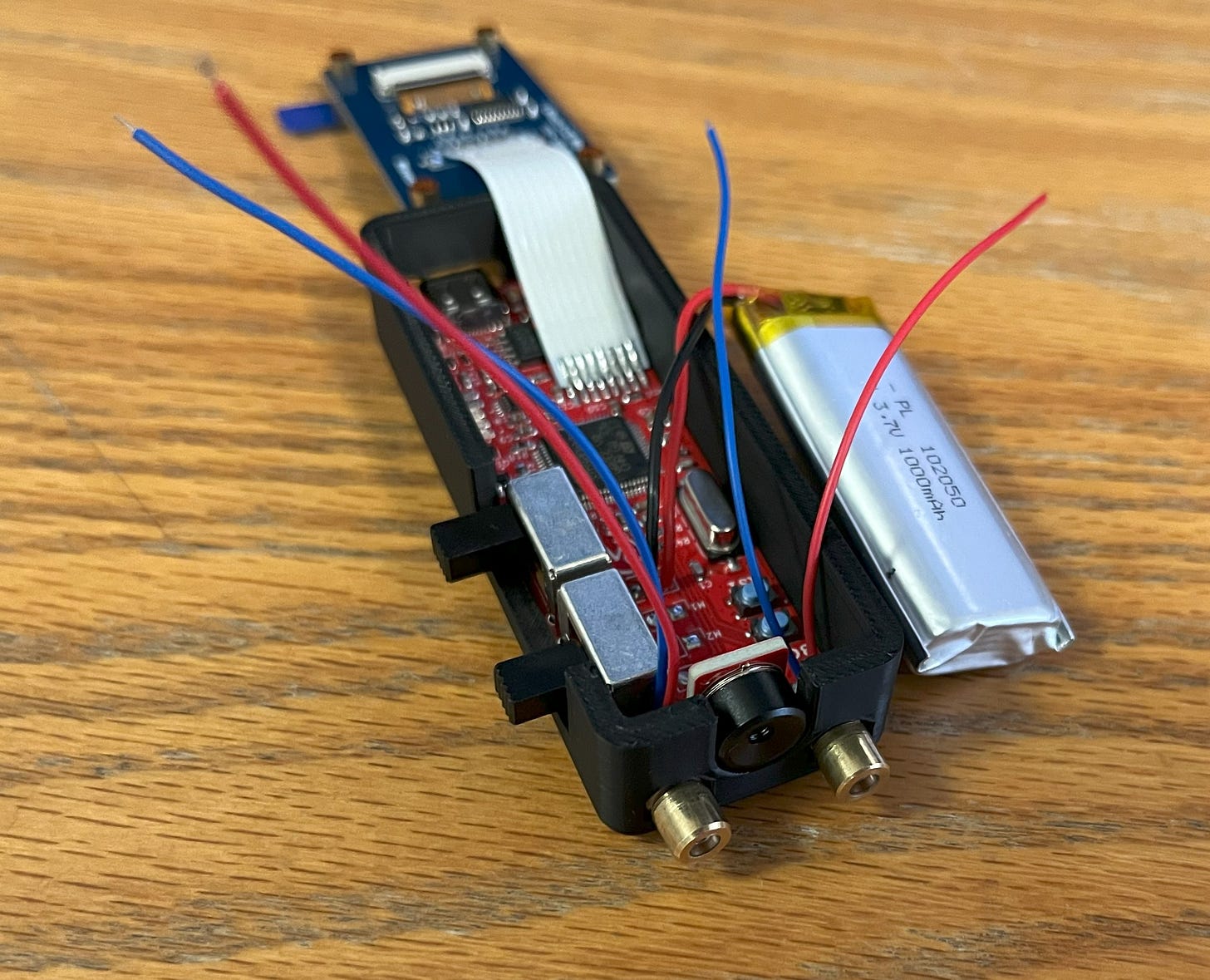
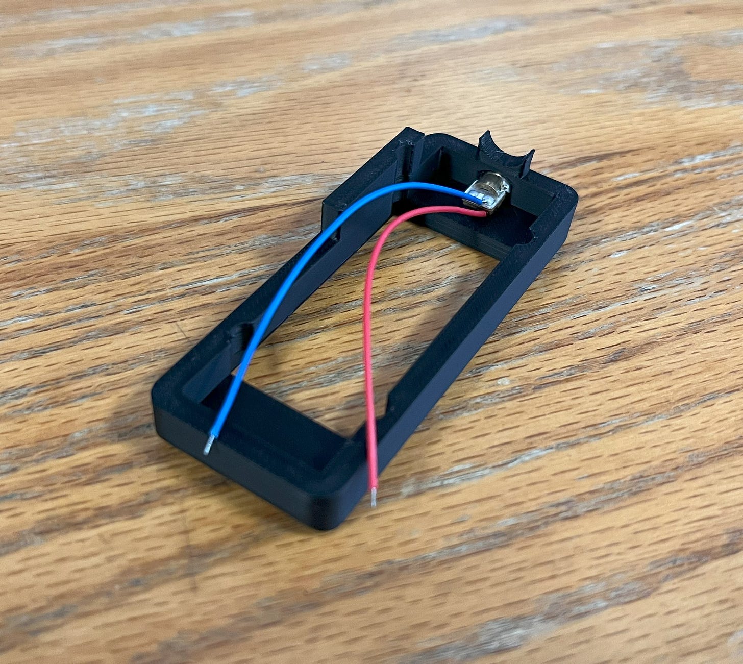
When that’s done, you can grab the loose wires of the laser pointers and solder them onto the PCB. The anode (positive) is still on the left! Which laser goes into which spot on the PCB doesn’t really matter.
With this, we need to align the lasers. Turn the board on and everything should come to life. Gently place the battery inside and hold on the lid. Then, go ahead and point it at a distant wall. There should be three dots from the lasers somewhere on that wall. Go ahead and adjust them slightly with your fingers until you are happy with their spacing, alignment, etc. Then, keep them there and let the glue you applied previously dry to freeze their positions. (Do your best to make sure the lid is flush with the casing for best alignment!)
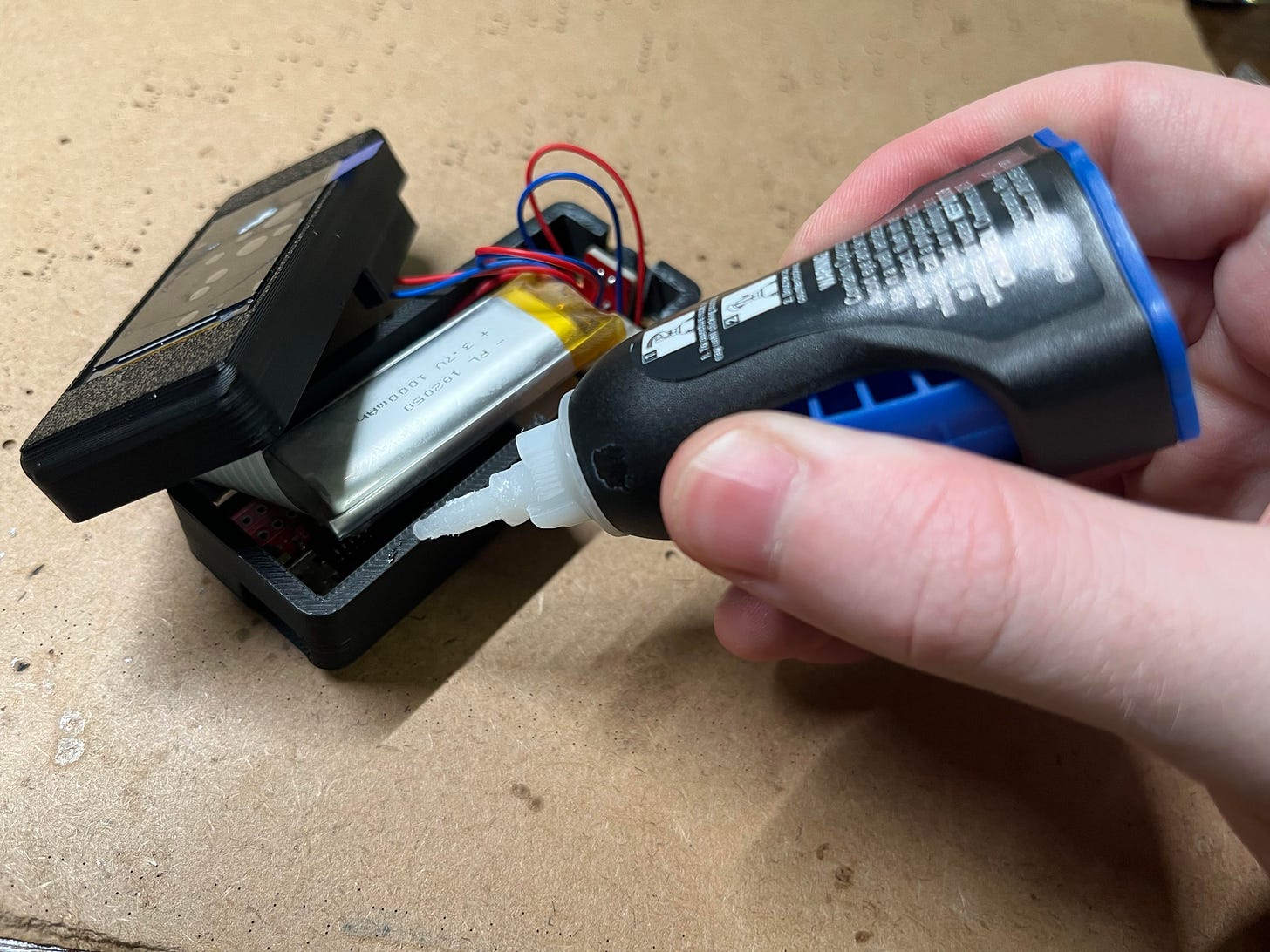
Great! After, when the glue is completely dried, it’s time to glue in the LCD. Apply a thin layer of glue and push down the LCD on top. Then, like the rest, wait for it to dry.
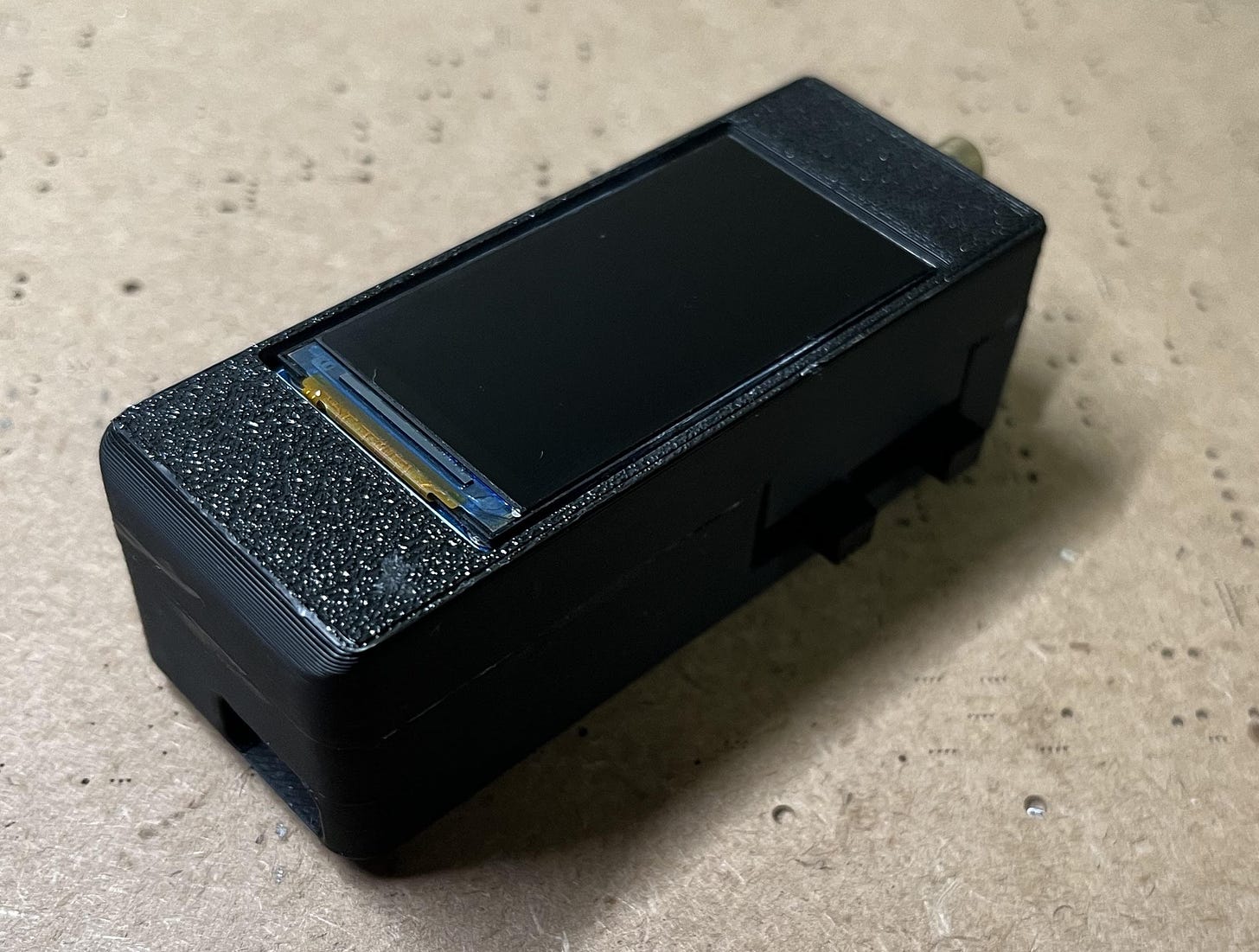
Final step! Place down a small layer of glue on the top of the casing and then place the lid over it. Do your best to align it, then wait for that to dry too.
IMPORTANT: You need to program the board before completing this final step because you need access to the BOOT button. Program the board with the instructions below and then complete this step.
That’s all! Enjoy your cool new gizmo. (Apologies about all the gluing, but it was necessary to keep everything small since adding bolts would’ve taken up a lot more space.)
Continued..
Programming
Being that this project uses an STM32 microcontroller, I thought it would be proper to write the program in STM32CubeIDE. CubeIDE is the official development environment for STM32s and gives you complete customization and control over each part of the microcontroller. This said, it is also a bit more complex than something like Arduino IDE and deserves a tutorial of its own.
I plan to write one soon that will include developing an STM32 board from scratch and the basics of programming it, but I wanted to get a bit more experience under my belt first in order to give you the best information possible.
Nonetheless, I have the full program available here for anyone who is interested in looking through the source code. It uses FreeRTOS, which is great for running “threads” in addition to LVGL (here is the FreeRTOS setup), which is a neat graphics library.
If you have not used CubeIDE before and would prefer not to mess with it, don’t worry because you don’t have to! This is all you need to do to flash (program) the PCB:
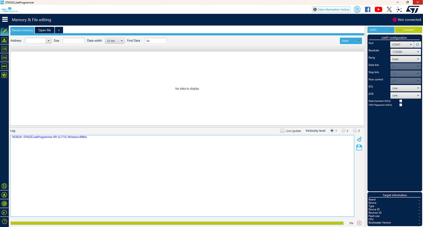
First, install STM32CubeProgrammer (installer info is at the bottom of the page). CubeProgrammer is a simple and small flasher software that you can use to upload precompiled files.
Once it’s installed, go ahead and open it.
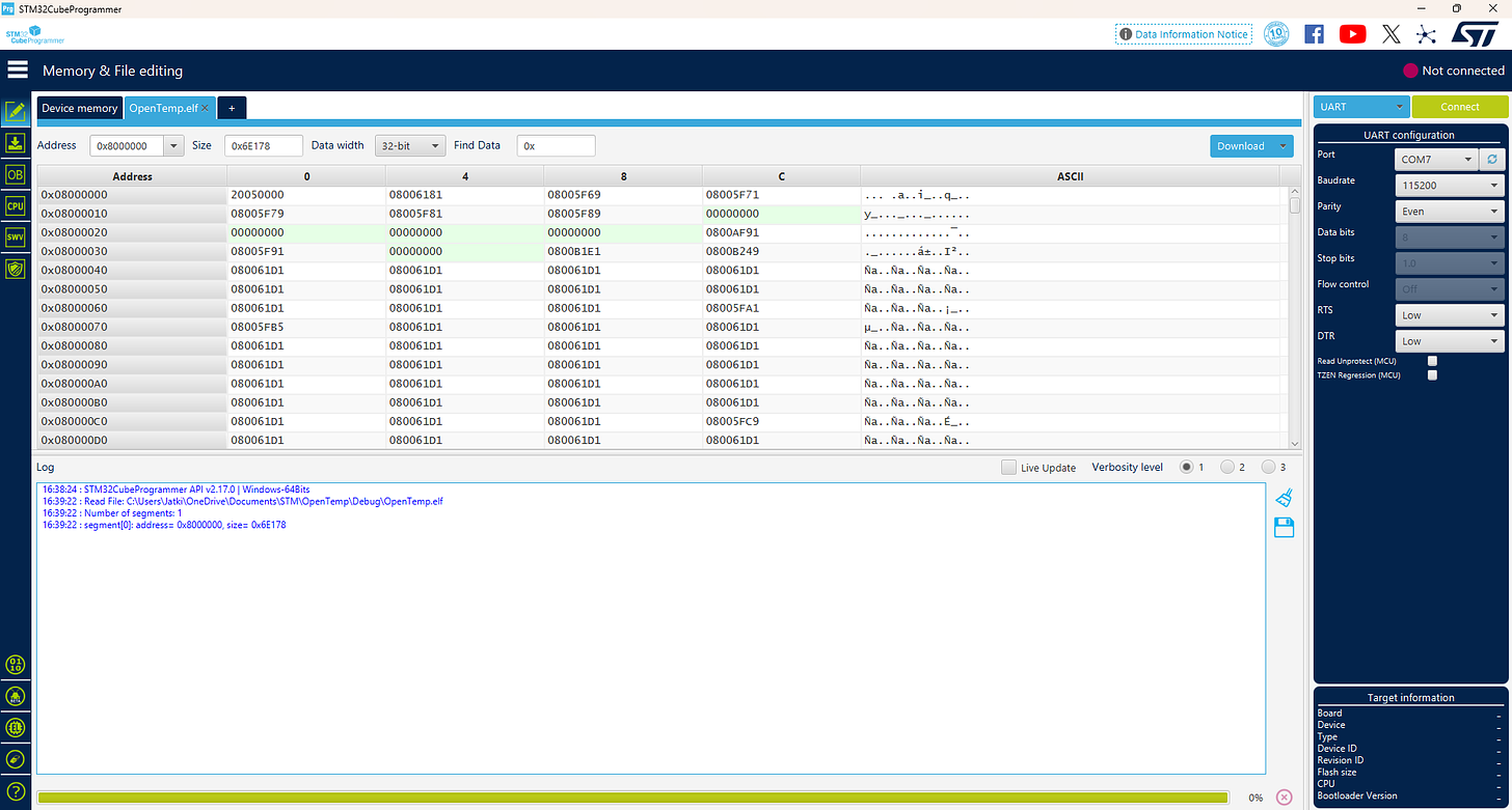
Then, click “Open file” at the top and select this precompiled OpenTemp.elf file (click “download raw file”).
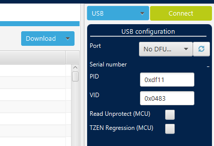
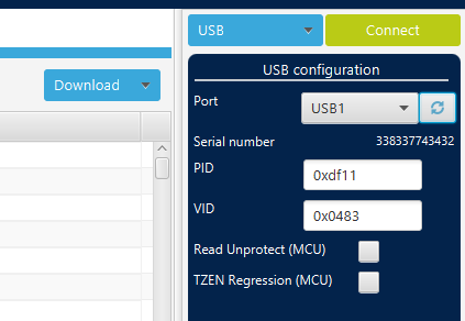
In the top right, click the “UART” drop-down and select “USB”
Now, plug in the PCB using a USB-C cable and flip the power switch to OFF. Then, hold down the BOOT button on the PCB and flip the power switch to ON while the button is still being held down. After that, you can release the button and click refresh on CubeProgrammer to the right of “No DFU…”. With that, it should recognize the USB port.
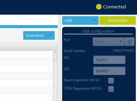
Then click “Connect”.
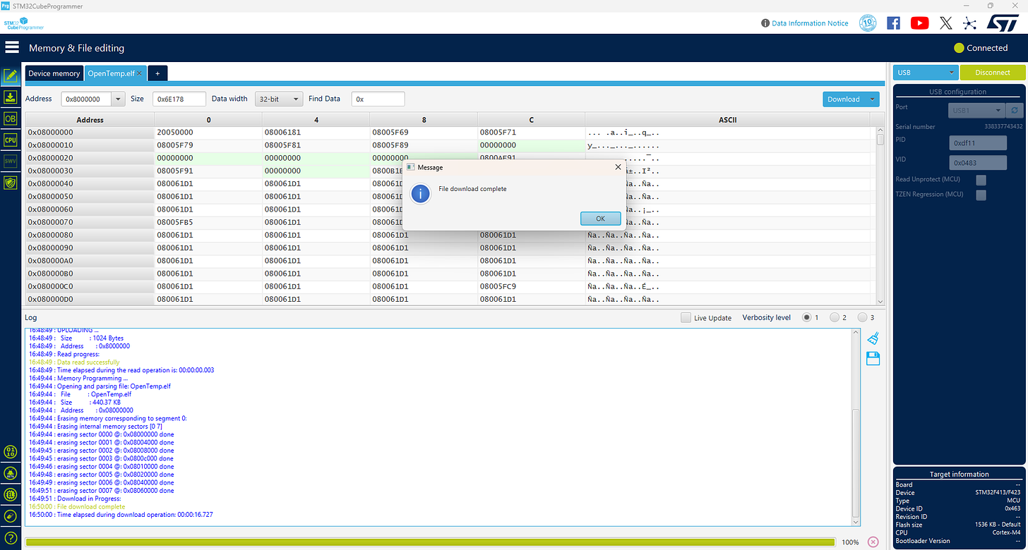
After that, click “Download” and it will upload the pre-built file to the PCB.
Next, click “Disconnect” and press the RST (reset) button on the PCB. With that, the board should come to life!
BOM
This is the Bill of Materials for my OpenTemp project!
I’ll put everything that you need to have here so that you don’t have to go scrolling around looking for the links I sprinkled throughout the article.
- All the CAD for this project can be found on my Thingiverse. Everything else including the Gerber files, part list, etc. can be found here on my GitHub.
- The editable STEP files, logo-less STL files, and editable KiCad PCB files are available here to paid subscribers. Thanks so much for your support!
- Laser diodes
- 1000mAh LiPo Battery
- 1.9” IPS LCD
- Super Glue
- Optional (if you don’t already have them):
- Mini soldering iron (what I use, but any will do)
- Solder paste
- Solder (my roll of choice)
- Hot plate
- Hot air rework gun (great for fixing broken or misaligned ICs)!
- Some nuts & bolts
- Basic screwdriver kit (one of many options)
Disclosure: These are affiliate links. I get a portion of product sales at no extra cost to you.
Thanks so much for reading! I hope this was a helpful and informative article. If you decide to do the build, please feel free to leave any questions in the comments below. If not, I hope you were still able to enjoy reading and learn something new!
Have constructive criticism or a suggestion for a future project? I’m always looking to improve my work. Leave it in the comments! Until next time.
Be sure to follow me on Instagram! :)
If you feel this read was worth at least $5, please consider becoming a paid subscriber on my homepage. I don’t use ads, so I rely on your support to keep going. This is a quick read for you, but I’ve been working on this for months! You will also receive the following benefits.
