Plot Clock for Dummies.
by Kjetil Egeland in Workshop > 3D Printing
98270 Views, 621 Favorites, 0 Comments
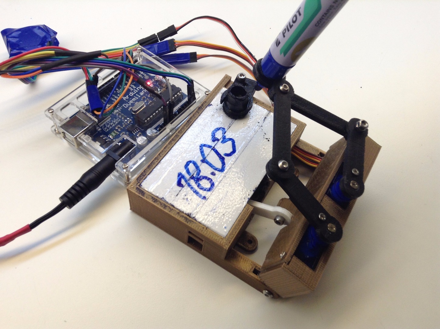
Plot Clock for Dummies.
Revisions:
1. Added the DS1307 real time clock module instructions.
This is NOT my idea, but I will try to show how I got this to finally work.
Often, the brilliant guys that make these stuff, forgets that there are idiots (like me) around, that need a lot of help to really understand the principles, and to have this fed by small portions.
So, I will make my own Instructions , hopefully in a understandable format for everyone.
But first, I will have to inform you that you will need a 3d printer, or get someone to print or lasercut this for you. If you are not really a handyman in woodworking..!
PLEASE TELL ME IF ANYTHING COULD BE BETTER EXPLAINED, AND IF SOME OF IT IS WRONG..!
Collect Information
I found this project here : http://www.thingiverse.com/thing:248009 , and think this is a GREAT idea..!
As always, there is a lot of different approaches to this finished clock. And I will try to make my own version of this , and what I ended up to use of software and hardware.
I started up with this original (?) post on GitHub .
I am not an expert on Arduino, so I quickly found out that I had to do some more research on this one.
But at least I printed the parts for the clock from the Thingiverse page.
Put it all together, and got the servos to work in a way.
I only got some bigger servos at the time, so I adjusted the brackets for this.
But I think it got to heavy, and got really "wobbly"
Re-mix
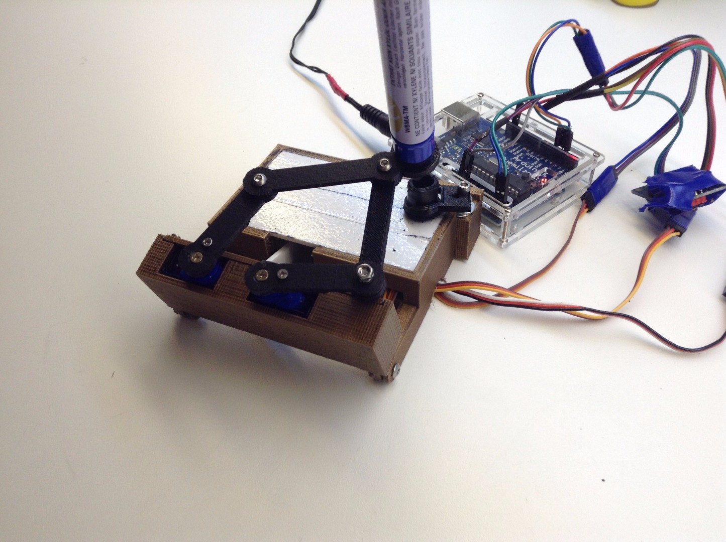
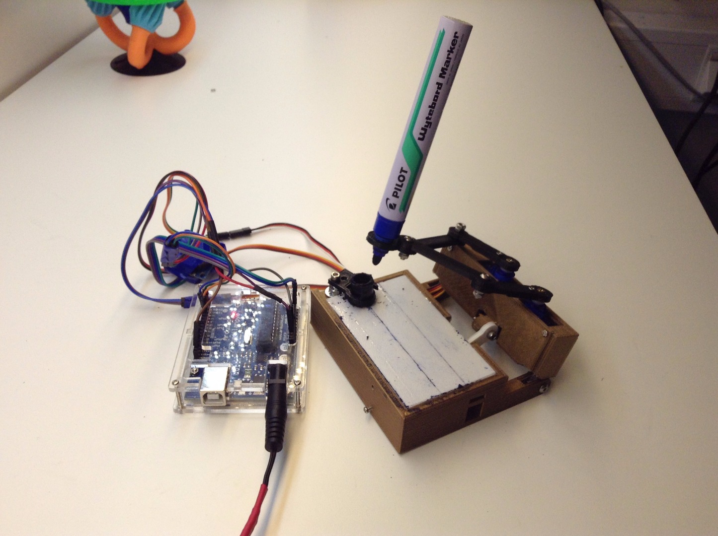
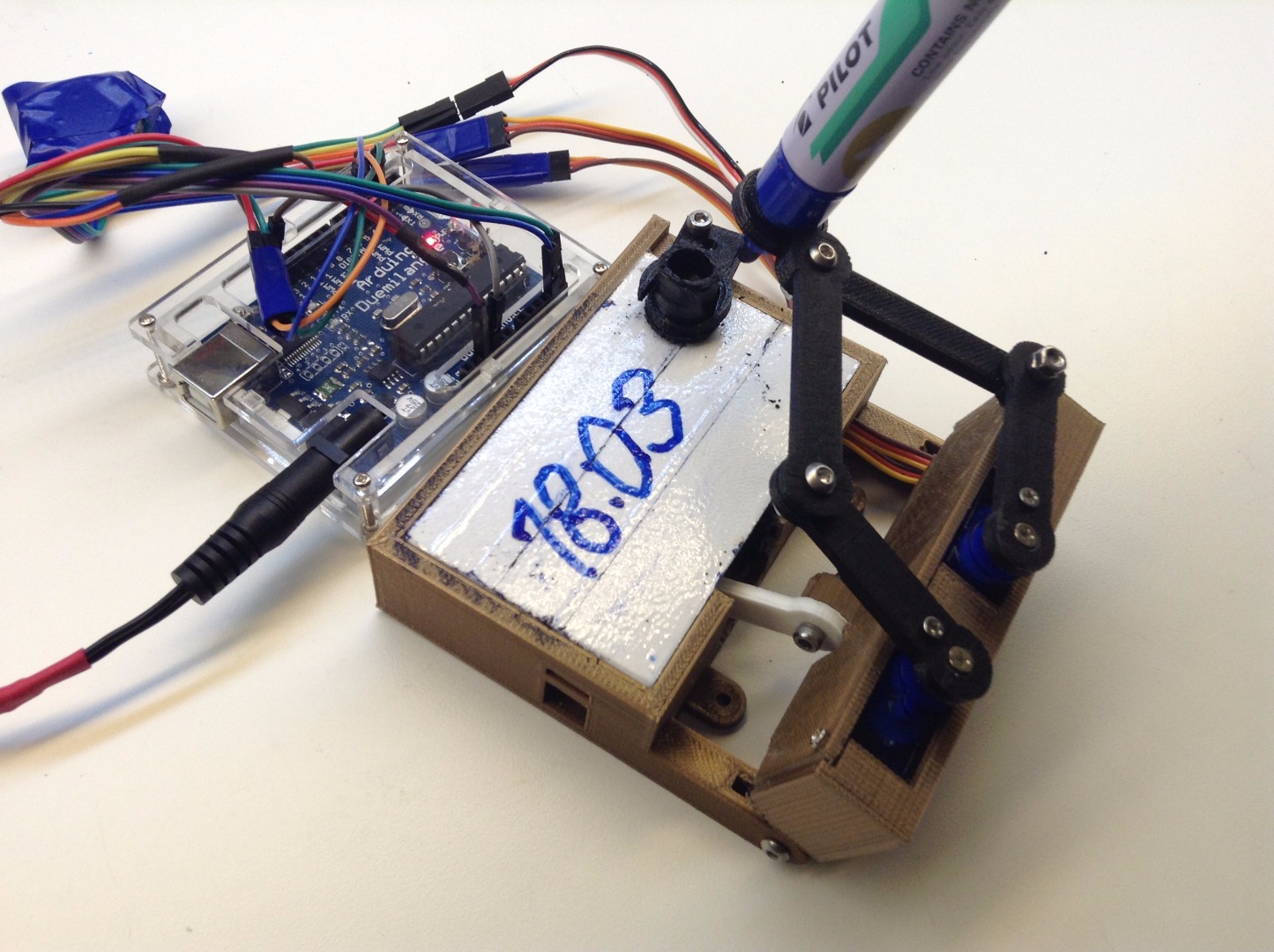
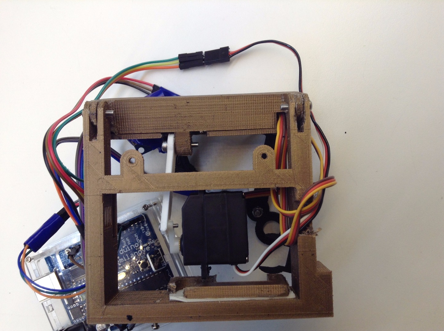
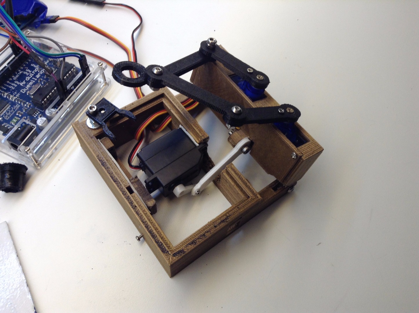
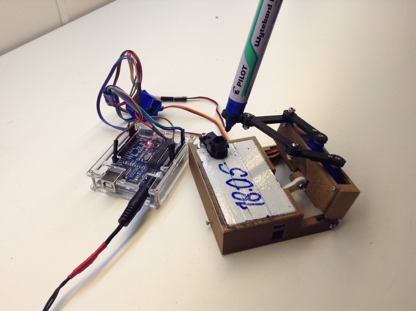
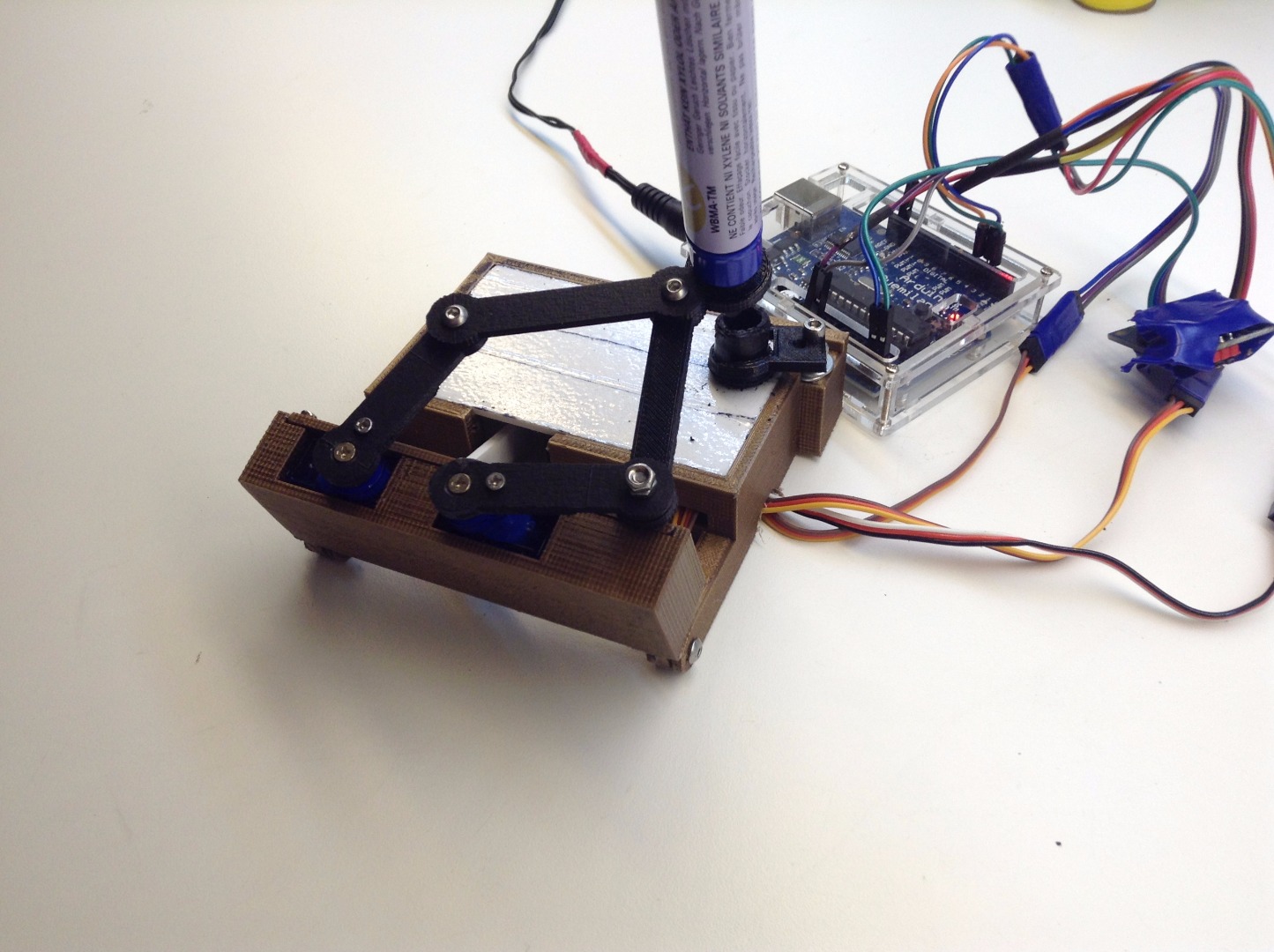
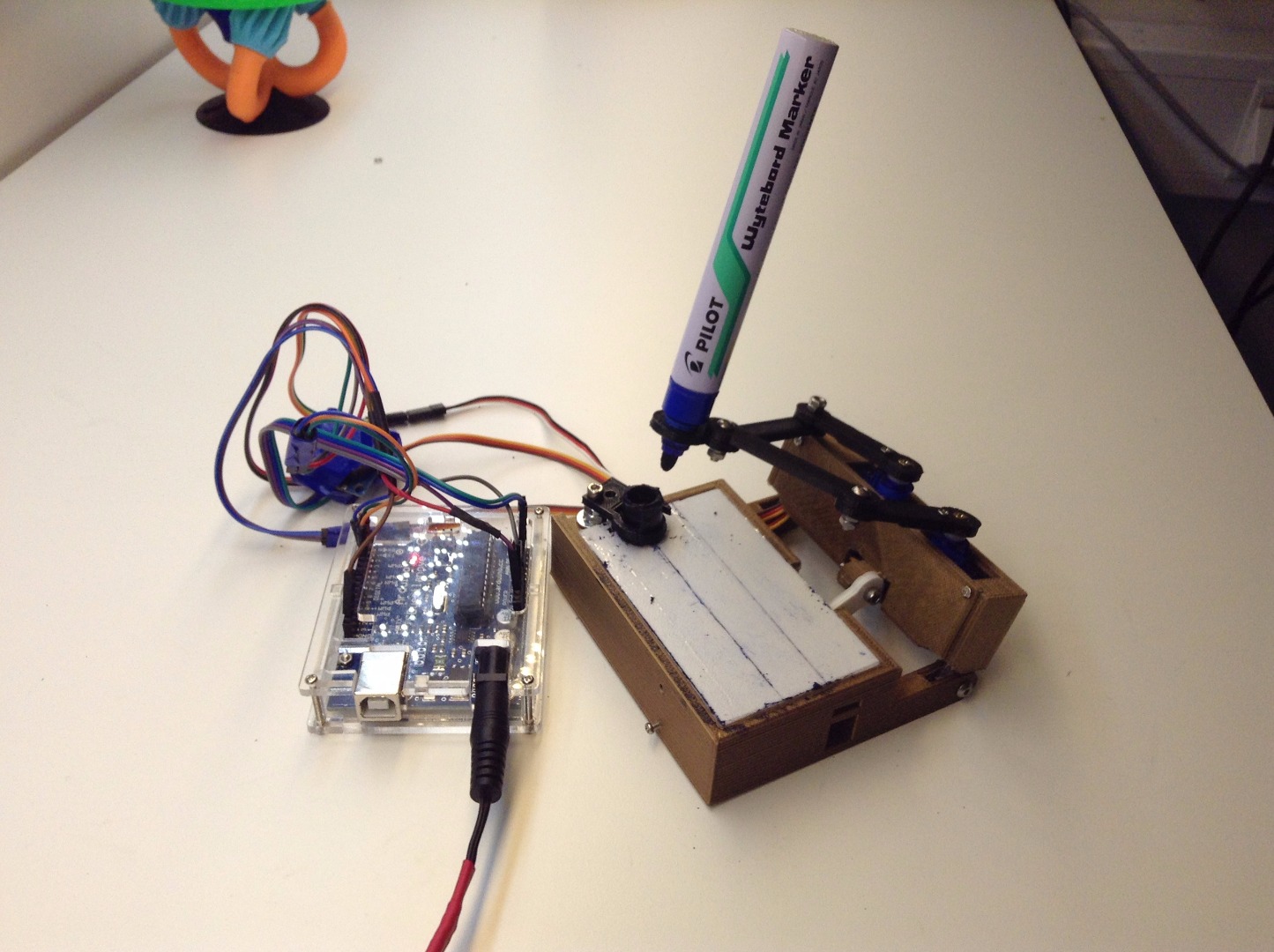
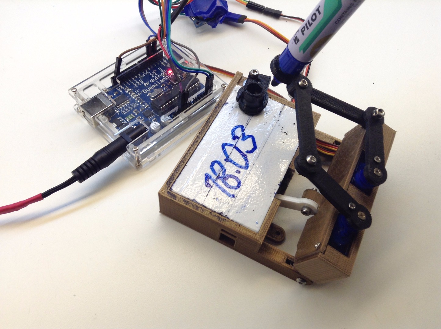
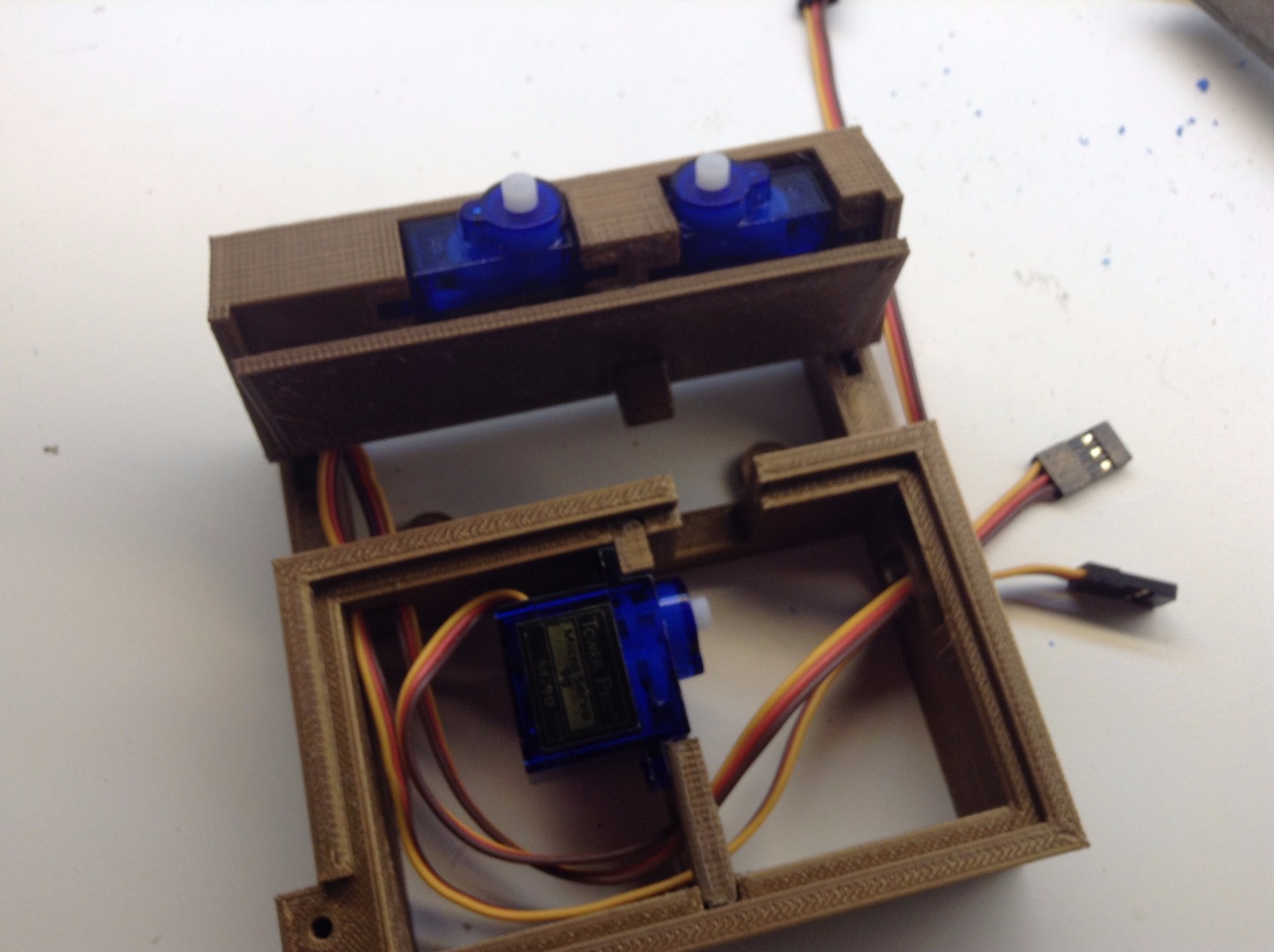
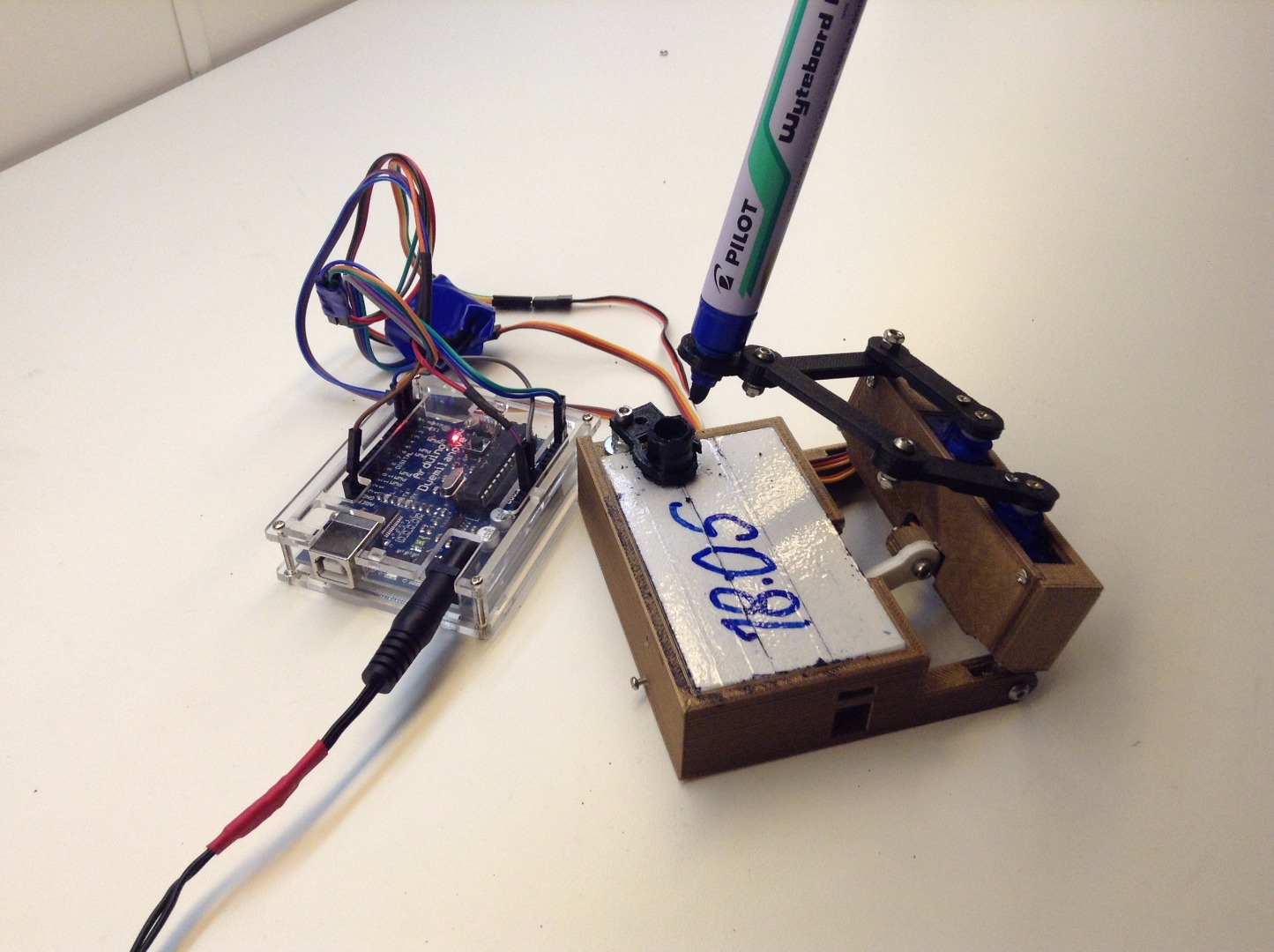
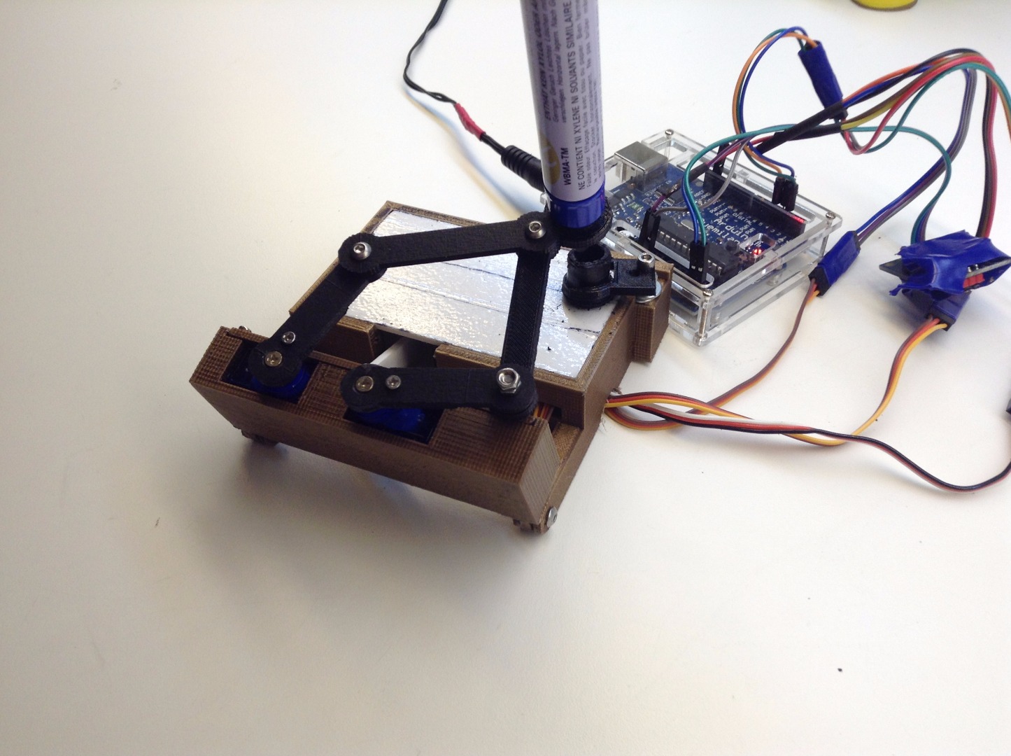

There is a lot of brilliant people out there, so I soon found better ways to make this clock.
Here in the remixes for this clock, I used this mix from "stylesuxx" This is all the parts you need for a good rigid clock. I hope its allright to share the files from Thingiverse here.
You will need some M3 and M4 screws and bolts. But it is easy to figure out. There is a lot of info about this in the original post, and in the re.mixes.
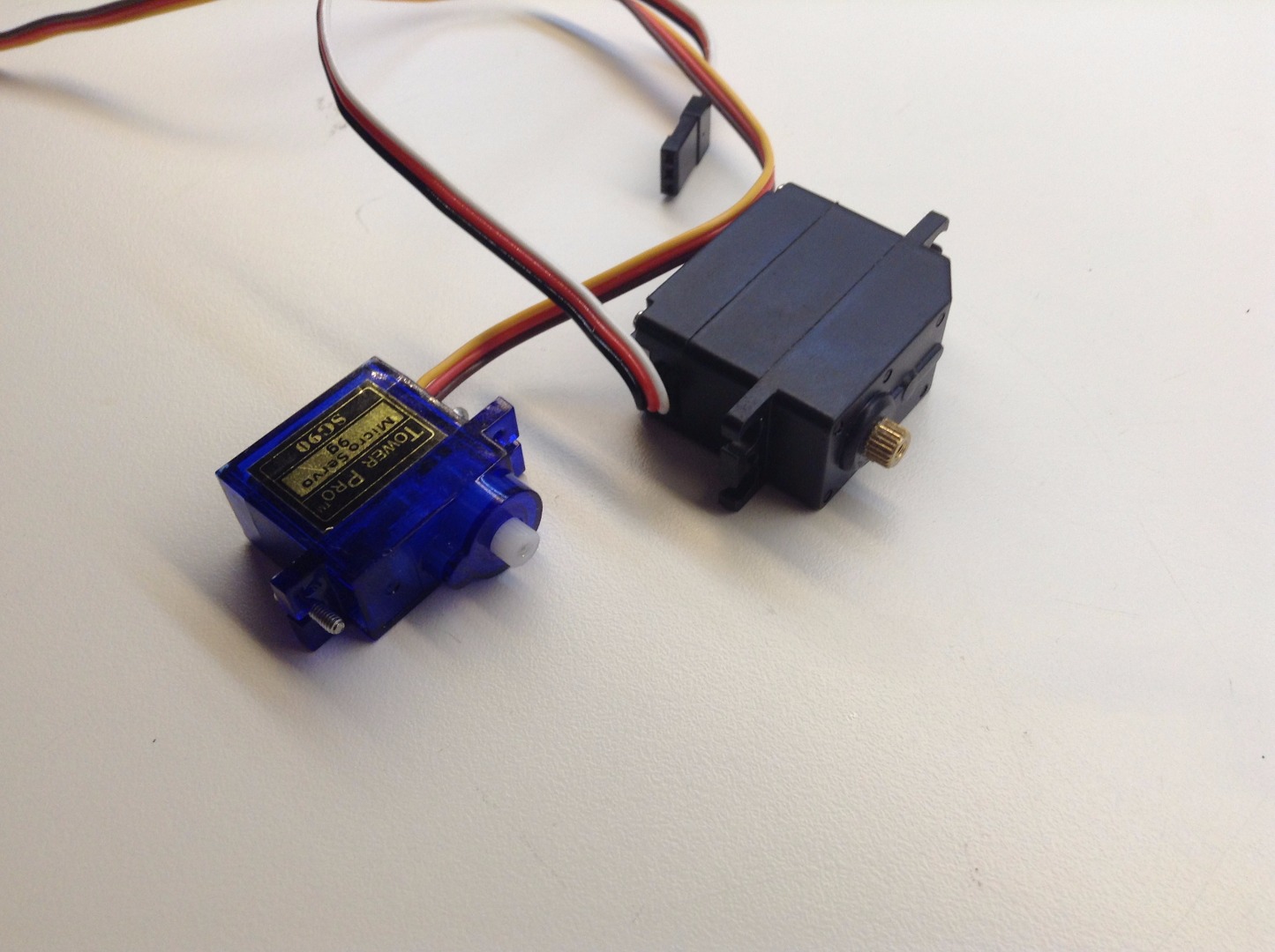
For servos, I used the Tower Pro 9g as suggested. After some troubles, I had to replace the up/down servo with a slightly bigger one with metal gears. I had problems with the servo arm slipping on the servo rod.
I also found out ,that I had to flip the servo to get it to work with the Arduino code.
Assembly and Wiring.
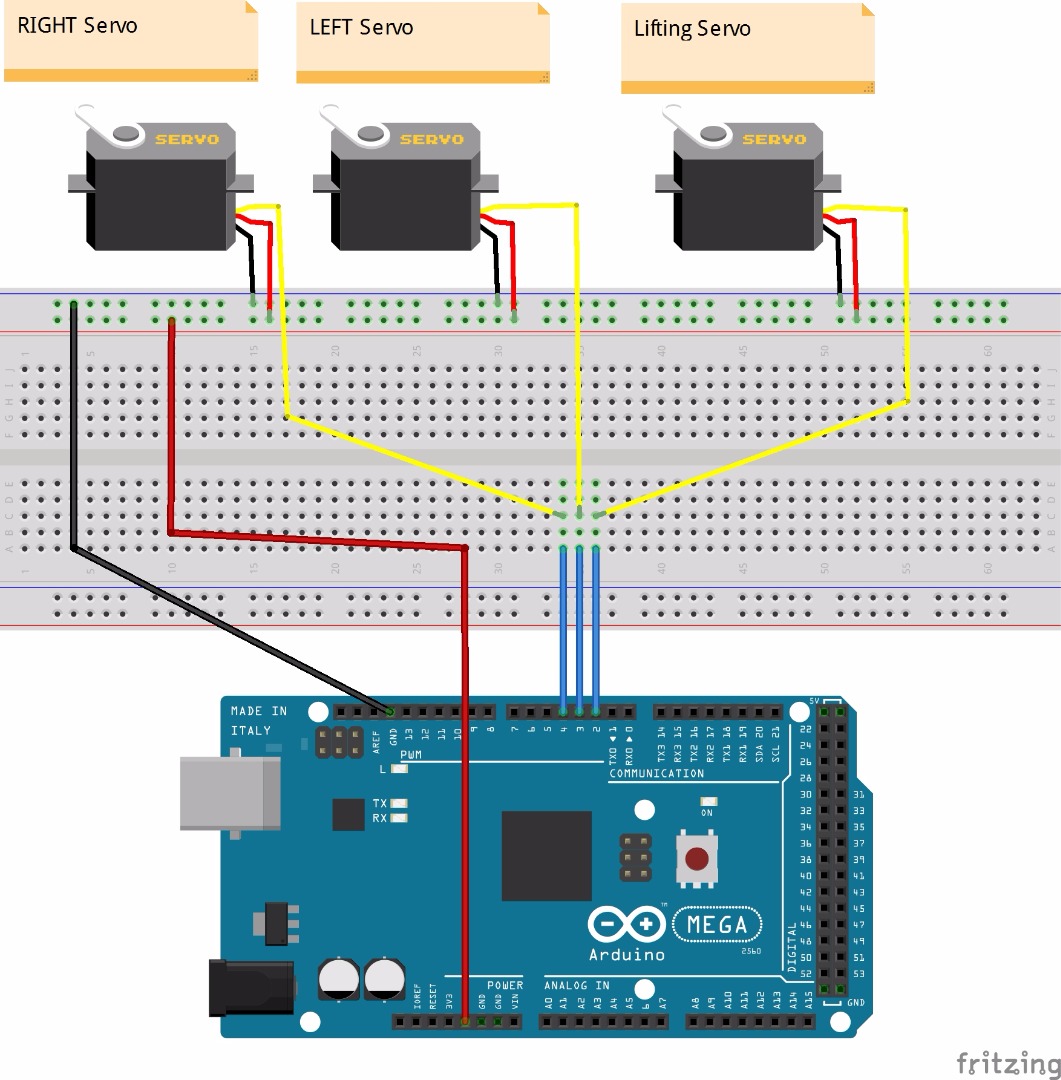
I can recommend the Fritzing software for making wiring diagrams for electronics. I had never used it before, but I managed to make this diagram in 5 minutes of how the wiring is done.
Its enough power from the USB cable. No need for external input, if you dont use extra big servos.
Arduino.
I used a Duemilanov , but I recon that you can use other like MEGA, UNO, and all that has the same pin out as required.
1. Download the Arduino software from www.arduino.cc
2. If you are completely new to Arduino, I recommend this BEGINNER ARDUINO instructable by amandaghassei
3. Run the .exe file, and install the Arduino software.
4. Open the plotclock_modded.ino file . Thanks to yajdlanor for this detailed instructions.
5. Choose Board and COM port used. Upload . All the needed librarys for this should already be installed.
6. Next, Calibration.
Downloads
Calibration.
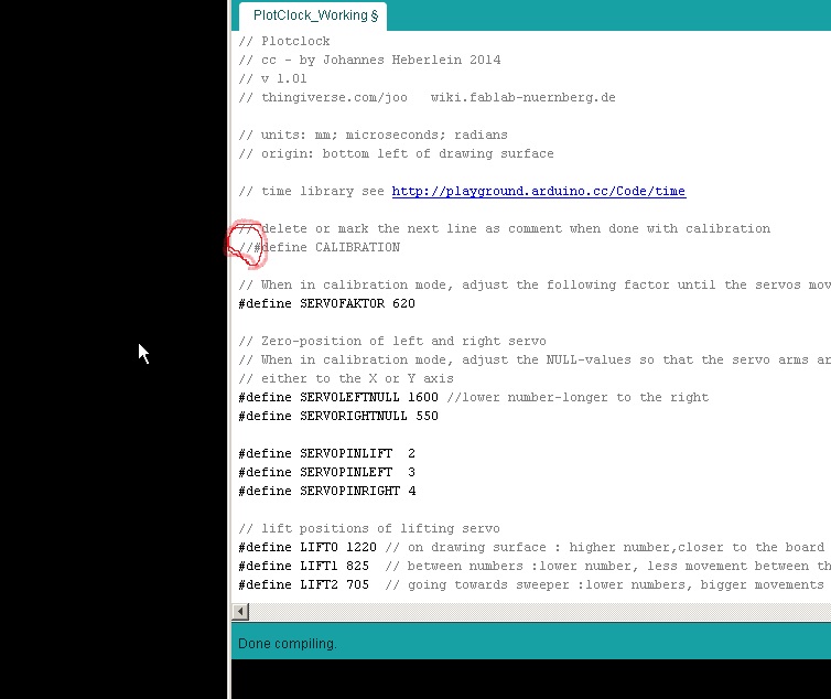
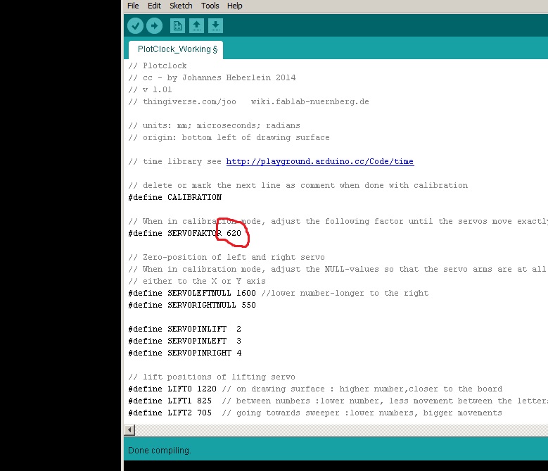
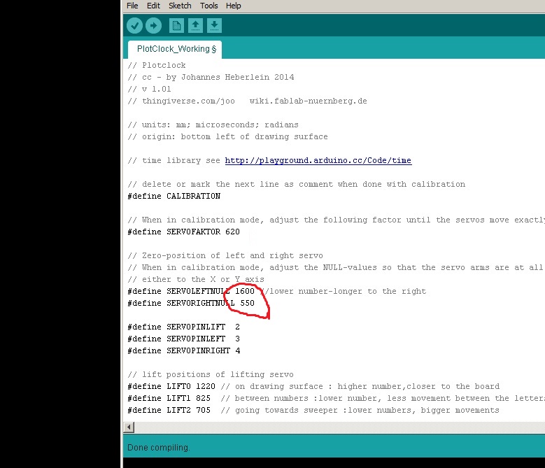
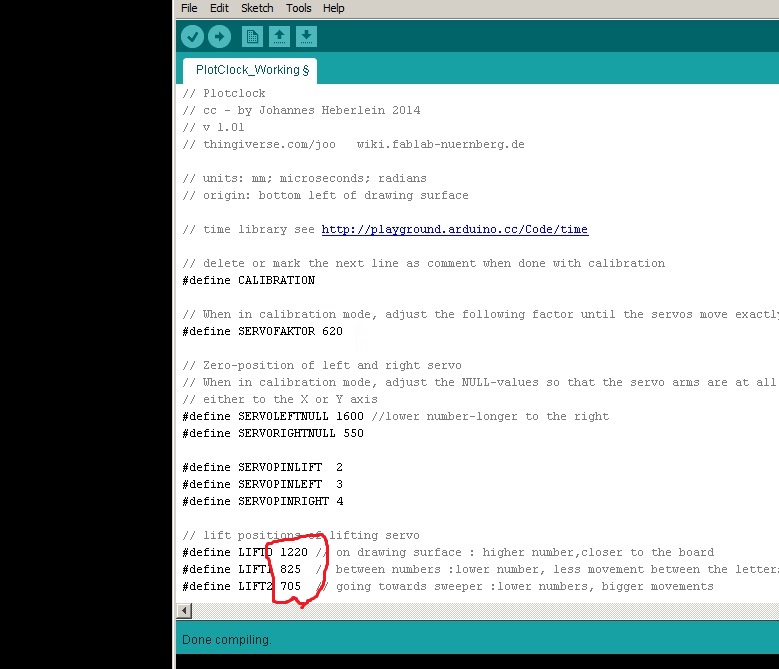
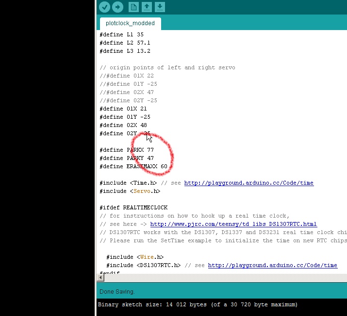
THIS.... is the tricky bit.
I will try to explain as good as I can. But do read the instructions for this in the original post, and the remixes first.
You will have to make small ,step by step adjustment to the Arduino file, and make notes how its behaving between each upload.
1. Set the Plot Clock in calibration mode by removing // in front of #define CALIBRATION
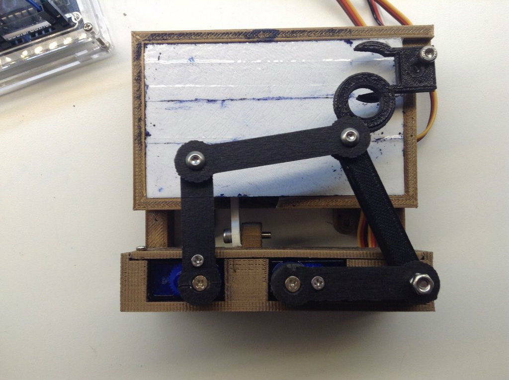
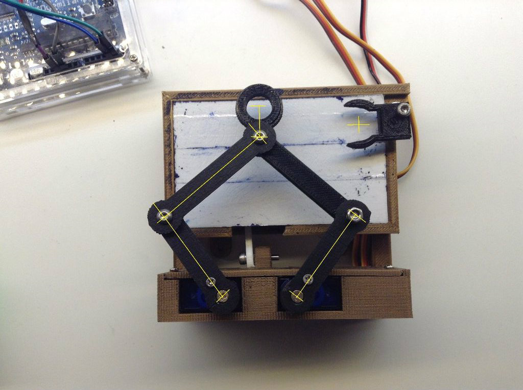
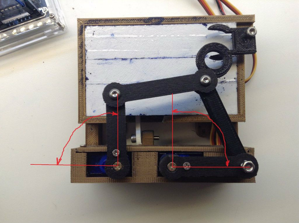
2. Attach an arm to the LEFT Servo ,pointing Upwards, and one arm to the RIGHT Servo pointing to the Right. Do not tighten the screw yet.
3. Power up the Arduino. The arms will start to go back and forth.
4. Adjust the SERVOFAKTOR so both arms moves about 90 degrees each.
5. Adjust the SERVOLEFTNULL and the SERVORIGHTNULL so the LEFT arm will move from pointing to the left to pointing straight up.. And the RIGHT arm from pointing straight up to pointing to the right.
6. When you are happy with the calibration so far, add // to the #define CALIBRATION. This will put the code in clock mode.
7. Upload to the Arduino board. Observe that all 3 servos will move back and fort like it should do for writing the time WITHOUT attaching the servo arms.
8. Power off the Arduino board, and attatch the servo arms. Try to position the arms, so the pen holder will be centered over the sweeper position. DO NOT tighten the arms yet.
9. Power up the Arduino, and watch that the arms would do something similar to writing the time on the board..!
10. Check that the UP/DOWN servo is moving in the right direction between the letters. If not, you have to turn it over, and attach it in some way inside the housing.
11. Adjust in small increments the number values : LIFT0, LIFT1, LIFT2,PARKX, and PARKY to get the movement you like for the Whiteboard Marker.
12. When you are happy with the calibration, attatch the pen, and try it out..!
Troubleshooting and Other Tips.


I will try to list up what problems I encountered.
The small servos was difficult to secure to the arms. Use the original servo arms , and glue to the L1 arms and the UP/DOWN arm if possible.
I had to modify the casing to fit a bigger servo for UP/DOWN movement.
This code is not written for this case, so the UP/DOWN servo moved the wrong way. Not sure how to modify the code for this to work the way it is. So I flipped over the servo instead.
Instead of polishing the board for the whiteboard marker, I just covered it with clear tape. Works just perfect.
Had a lot of problems with the DS1307RTC library. So I just adjusted the time by uploading the code with the right time setting.
REMEMBER to do the calibration all over again if you have removed the arms, or they have moved themselves..!
The arms must be completely tighten, or else they will move out of position if they get some resistance.
Add DS1307 Real Time Clock to the Arduino.
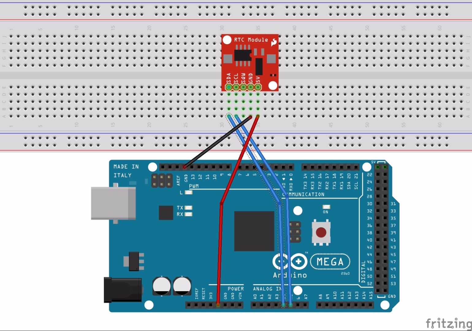
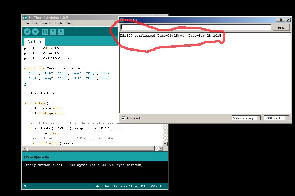
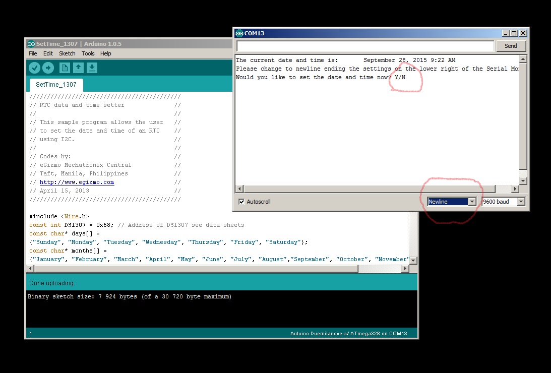
When you are comfortable with the clock, and are ready to add a clock module to the Arduino, then you can follow these steps:
1. Buy a real time clock like this from Adafruit.
2. Download the DS1307RTC.zip file.
3. Unpack,and put the DS1307RTC folder in to the library folder in your Arduino program location.
Wiring from DS1307 to the Arduino board:
GND - GND
VCC - 5v on Arduino
SDA - Analog pin 4
SCL - Analog pin 5
4. Run the Arduino software.
5. Now , the DS1307RTC library should show in File-Examples-DS1307RTC
6. Under File-Examples-DS1307RTC , there is is a "ReadTest", and a "SetTime" option. Choose "SetTime"
7. Upload to Arduino. Remember to pick the right board, and COM port.
8. When uploaded, open Tools-Serial Monitor. (Or ctrl+shift+m)
9. If the module is correctly wired, it should read the current time. If this is correct, you are finish.
10. Open the Plotclock_modded.ino again. Remove the // in front of #define REALTIMECLOCK
11. The clock should now use the DS1307RTC module to set the correct time.
If the time and date is wrong, follow these steps:
1. Open SetTime.ino from eGizmo with both the clock servos and the DS1307RTC module attached.
2. Upload to the Arduino board. Remember to check for correct board and COM port.
3. Open serial monitor. (ctrl+shift+m)
4. Follow the instructions for setting the time and date.
5. The date and time should now be correct.
6. Upload the Plot clock Arduino code again to check if the time is correct.
Good luck ... !