Plastic Antweight Combat Robot Design
by CJGriz365 in Circuits > Remote Control
13252 Views, 50 Favorites, 0 Comments
Plastic Antweight Combat Robot Design

I am in 9th grade currently attending Lewis Palmer High School in Colorado.
At a robotics club exhibition we held a plastic antweight completion. I had always loved the show battle bots back when I was in elementary school. After watching the robots face off with each other I was inspired. I thought "I could do this" and started working on my first design. In this instructable I will take you though the process of designing and building a combat robot using Fusion 360.
Supplies
Tools Required:
- Autodesk Fusion 360 or another 3D design software (I will be using Fusion 360)
- 3D Printer
- Drill and Drill Bits
- Ruler/Digital Calipers
- Soldering Iron and Solder
- Screw Driver
Other Tools:
- Laser Cutter (Not required)
Parts Required:
- Receiver and Transmitter (I use this radio and this receiver)
- 20amp Brushless ESC (Electronic Speed Controller) (Use only if your robot design requires it)
- 1806 Brushless Motor (Use only if your robot design requires it)
- 9 Gram Servo (Use only if your robot design requires it)
- 2s 7.4v 500mAh battery with charger
- Electrical Tape
- Double Sided Servo Tape
- Some type of small screws with large threads
- Dual 5a Brushed ESC (I used this one)
- 2x N20 500rpm 6v Brushed Motors
- Acrylic 3mm (Not required)
- Lego Tires
Understanding the Engineering Process

The engineering process is a amazing way to get a successful and working machine or product. The engineering process has 8 main steps to get you a working product.
- Identify the Need or Problem(Determine the problem or need required to get your product working)
- Research the Need or Problem(Research fixes or solutions for your problem or need)
- Brainstorm/Develop Possible Solutions(Brainstorm many different ideas and solutions to your problem or need)
- Select the Best Possible Solution(Decide on the best possible solution or change needed)
- Construct a Prototype(Build/construct a prototype or change in your design)
- Test and Evaluate the Solution(Test to see if the prototype fixed your problem or need)
- Communicate the Solutions(Determine by reviewing the testing if you fixed your problem or need)
- Redesign and Restart the Engineering Process Until Complete
Determine What Type of Combat Robot

When I decided to start designing and building a combat robot I decided on a shell spinner design. After designing and building the shell spinner I found that I was in way over my head for my first robot. I decided to scrap my original design and design a horizontal spinner robot. A horizontal spinner bot is a robot that has a piece of spinning flat plastic in the front. This design was so much more simple than my original shell spinner. There are many different types of combat robots you can build.
Types of Combat Robots:
- Drum Spinner(Requires a Brushless Motor)
- Horizontal Spinner(Requires a Brushless Motor)
- Vertical Spinner(Requires a Brushless Motor)
- Shell Spinner(Requires a Brushless Motor)
- Ring Spinner(Requires a Brushless Motor)
- Wedge
- Flipper(Requires a Servo Motor)
- Rammer
- Lifter(Requires a Servo Motor)
- Clamper(Requires a Servo Motor)
This video is great for learning the different types of combat robots: Adventures in Science: Combat Bot Weapon Types
Simple Combat Robot Designs:
- Flipper
- Lifter
- Rammer
- Clamper
Intermediate Combat Robot Designs:
- Drum Spinner
- Horizontal Spinner
- Vertical Spinner
Complex Combat Robot Designs:
- Ring Spinner
- Shell Spinner
Choosing a Design

If you are just starting out with designing and building combat robots I would recommend choosing a robot type from the list of simple combat robot designs. If you have some experience you could choose a robot type from intermediate or complex robot designs as well.
For my design I chose a horizontal spinner robot.
Electronics Required for a Horizontal Spinner Robot:
Determining Constraints and Materials
Determining constraints is extremely important before starting you design. A constraint is a limitation or restriction that you design has to follow.
Some Possible Constraints:
- Weight limit (The plastic antweight weight limit is 1Ib)
- Size (There is no size limit for plastic antweights)
- Electronics
- Ease of Assembly
- Chassis and weapon must be made out of plastic
Before starting your 3D model you need to decide on what type of materials you will be using. Since your chassis and weapon must be made of plastic it important not to choose a material like metal. I chose to use mostly 3D printed parts and 3mm acrylic for my final design. If you choose to use 3D printed parts in your design it is important to know you 3D printers tolerances and make sure to model your parts with those in mind. I use a ender 3 pro printing with a 0.3mm layer height and model with a 0.3mm offset on my parts.
Starting Your Design

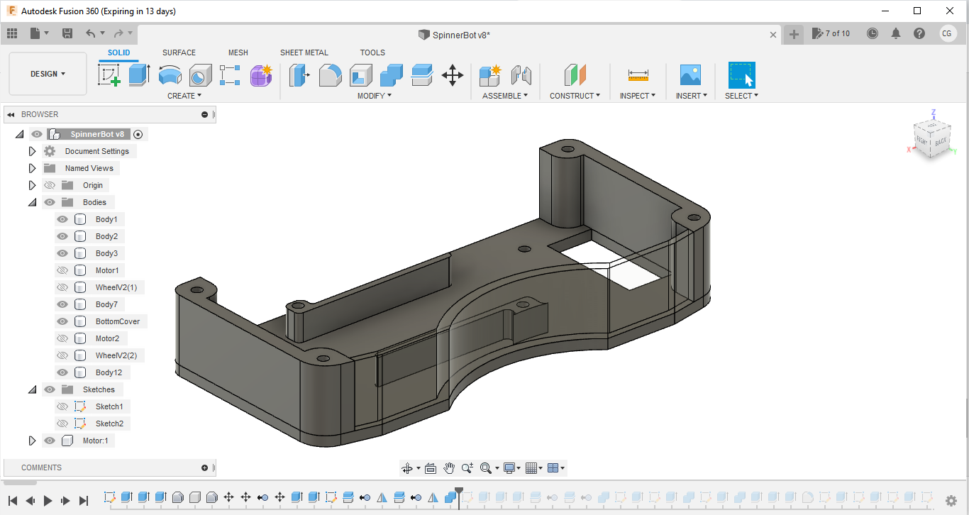
When starting your design you want to take the dimensions of the electronics you are using into mind. I will take all of my electronics and put them in one pile. This helps me determine the size of my robot to model. I started my design with basic dimensions of the electronic and wheels I was going to use. When starting a design you always start with a sketch. Even if the sketch is on paper or in Fusion 360 it is important to start with.
When starting my sketch I made a box around the size I determined from my pile of electronics. I then added in wheel slots, and areas for electronic and the spinner. I like to design symmetrically since it is less work and makes the assembly easier. After finishing my sketch I started to make the design 3D by using the extrusion tool in Fusion 360.
After getting my basic design done I decided to start working on the acrylic plates I wanted to use for the motor mount and chassis. I also updated my chassis design by adding chamfers to the back to make sure that it would not get stuck on its back. I added some wheel and motor access doors on the side of the chassis.
Adding Electronics Mounts


After getting my basic design done I decided to start working on the acrylic plates I wanted to use for the motor mount and chassis. I also updated my chassis design by adding chamfers to the back to make sure that it would not get stuck on its back. I added some wheel and motor access doors on the side of the chassis. I added motor mounts for the N20 motors and the brushless motors using dimensions from my electronics. I found all of my dimensions using a ruler.
Once I finished my motor mounts I started working on removing material from the acrylic plates. I did this by creating a sketch and using to offset and fillet tools to create a shape to then remove with the extrude tool. I also added some screw holes for the brushless motor on the front. I then removed more material from the acrylic plate and added the other N20 motor mount.
Upon finishing my acrylic plate design the robot was almost complete. Except for one thing... THE Weapon. For this I created a sketch with a circle using the circle tool in Fusion 360. I then used the spline tool to cut away material form the spinner. I created a hub that would then mount to the brushless motor and join the spinner to the robot.
Finalizing the Design


In order to finish my design I needed a top cover and mounting holes for the frame. To create the top cover I made a copy of the bottom plate and removed the holes to mount the brushless motor. After this the top cover was complete and all I needed now was to add the mounting holes for the frame. To make the mounting holes I created a number of 6mm diameter columns with a 3mm hole through the middle. I then spaces these throughout the frame where I thought would be best. I then used the combine tool to attach these to the frame. I then added in fillets of 3mm for structural support. I then removed 3mm holes from the top and bottom plates in places where the screws would sit. After this my design was complete and I could start 3D printing.
If you would like to build this bot you can download the files below.
3D Printing and Preparing Parts

The entire robot took around 8 hours to print at a 0.3mm layer height and 75% infill. The filament I used is the Creality black PLA. I also printed with an extrusion temperature of 210 and bed temperature of 60. You could print at a higher extrusion heat if you filament can handle it. Printing at a higher head gives better layer adhesion and strength. After printing the parts I went through and drilled all of the 3mm holes with a 3/16 drill bit. You can also sand and paint the parts for aesthetics.
Soldering Electronics


The ports M1 and M2 on the dual ESC get soldered to the N20 motors. The battery leads from both ESCs get soldered to a battery port and the receiver wires get plugged into their corresponding ports on the receiver.
Assembly


- Attach the bottom cover to the main chassis with 4 screws.
- Attach the 2 side walls to the bottom cover with 2 screws.
- Assemble the wheels and attach them to the N20 motor shafts.
- Mount the brushless motor to the bottom cover using 2 screws that came with the motor.
- Attach the N20 motors to the frame with super glue.
- Mount the dual ESC under the dual ESC cover with double sided tape.
- Mount the brushless ESC to the back wall with double sided tape.
- Attach the batteries and receiver as well.
- Attach the motor hub to the spinner as secure with a nut.
- Attach the top cover with 8 screws and your combat robot is complete.