Plant-radio
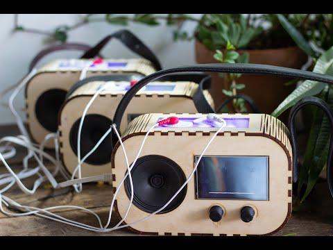
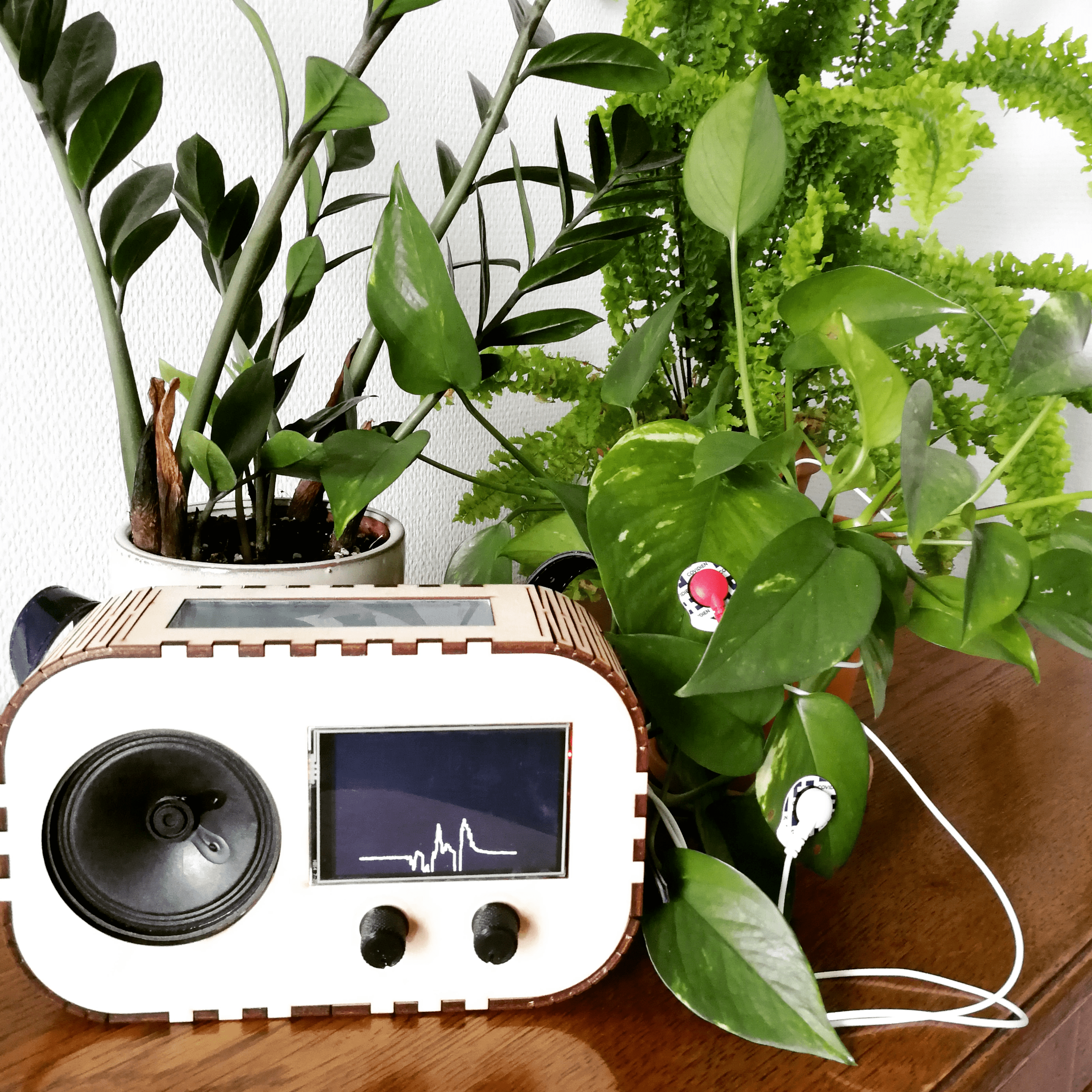
The plant-radio was build to enhance people's relation with their plants by being able to tap into the plant's electrophysiological signals and output the data as sound, pulsating lights and a graph. It was produced as part of a research project called Growing CoDesign, and we want it to live on here on Instructables for other people to have the same experience of communicating with plants.
In the video you can hear how the radio sounds.
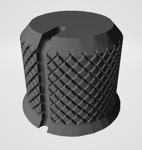
Casing: The main body of the radio is made in laser cut plywood. We've 3D printed the turnknobs and also a mount that is inside the radio holding the LED strip in place. In our version we've also attached a leather strap onto the radio to make it portable, but this is optional for you to do.
Software: The radio runs on a raspberrypi 3+, where the data comes from an EMG sensor into an Arduino sketch, which controls the LED lights and forwards the data to a Processing sketch that draws the graph, and also a OpenData patch that handles the sounds.
The following libraries are used: [to be added]
Download the Github repository for the code, the lasercut- and 3Dprint-files
Supplies
Equipment and tools:
- Laser cutter
- 3D printer
- Soldering iron
- Electrician screwdrivers
- Wrench
- Tape, wood glue and glue gun
- Screws M2,5 3mm
- Bolts M2,5 25mm
- Small paintbrush for applying wood glue (optional)
- Cable shoes (optional)
Casing:
- 1 sheet plywood for laser cutting
- Transparent acrylic sheet for laser cutting (optional, can be substituted with parchment paper)
- Leather strap and patent buttons (optional)
Technology:
- 1x Potentiometer 1K resistance
- 1x Potentiometer 100K resistance
- EMG sensor
- Power supply board
- Sound board
- Raspberry pi + micro SD card with operating system flashed onto it
- Arduino pro trinket
- Speaker
- Resistance
- LED strip
- Screen
- USB cable (for power to raspberry)
- USB port extension (for charging)
- USB serial adapter (for trinket and raspberry connection)
- Wires
Step 1: Preparations for the Casing
Lasercut
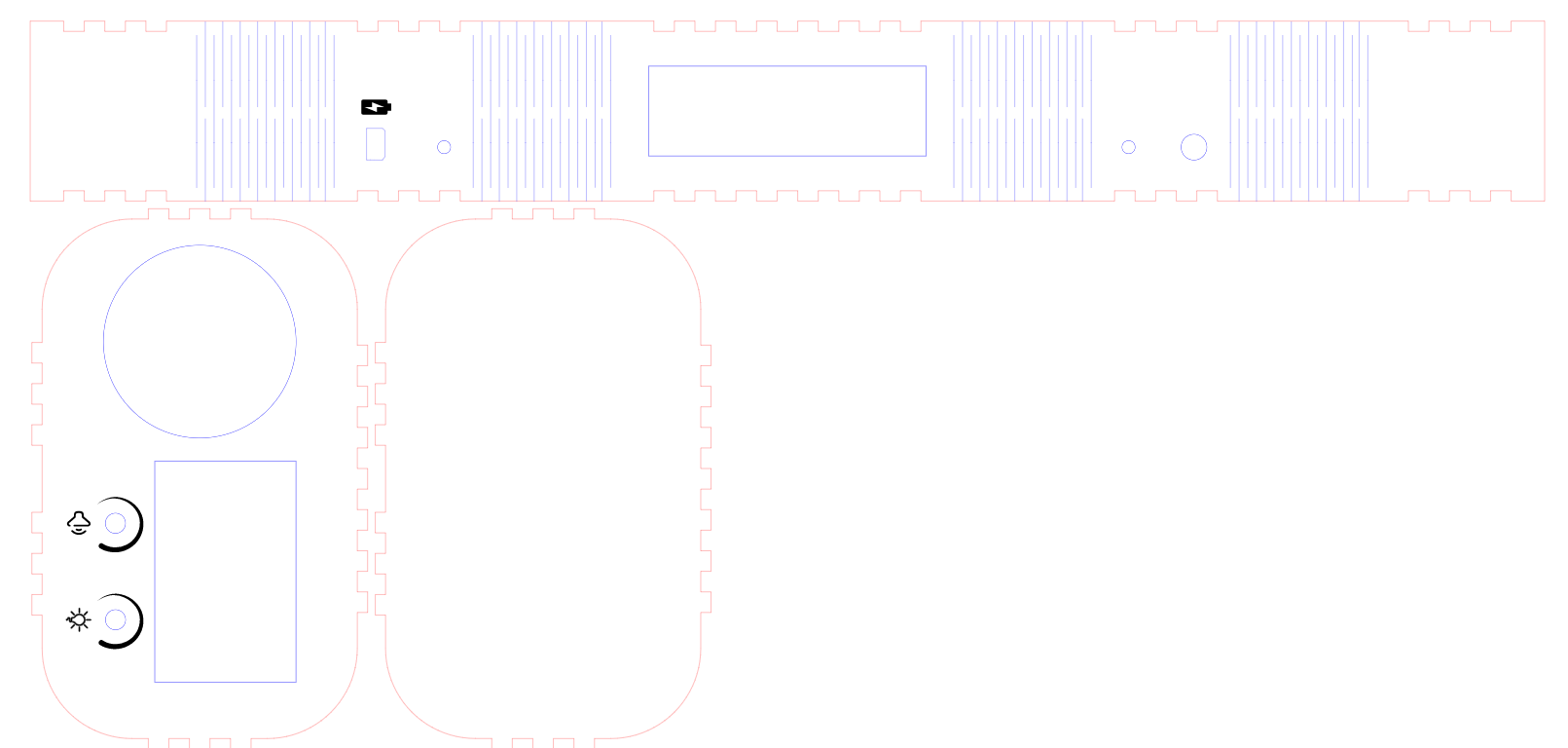
Fetch the SVG file in the Github repo and lasercut the main body of the radio, which consist of a front and back panel, and a bendable ribbon that forms the sides.
Lasercut the acrylic sheet to make the LED 'window' on the top of the radio. Do this by fetching the big rectangular shape from the SVG file of the casing. Be aware that the laser cutter might melt some of the sides more than the measurements, so this might take some trial and erroring before the window fits snuggly in the ribbon.
3D print
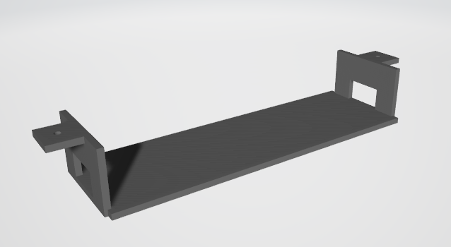
Fetch the STL files in the Github repo and print 2x turnknobs and the 'LED Bridge' that will be mounted inside the radio to support the LED strip.
Step 2: Assembling the Casing - Ribbon
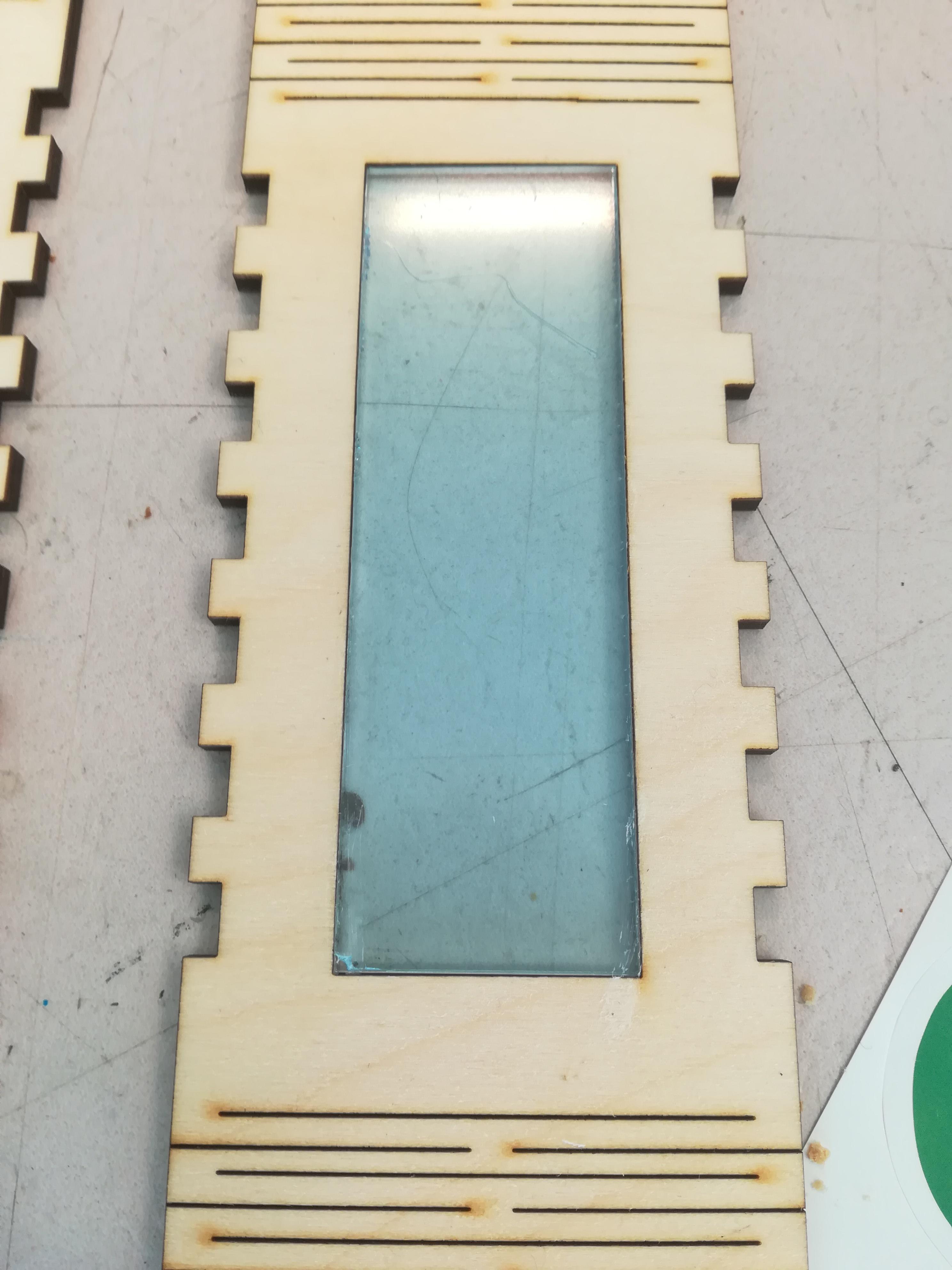
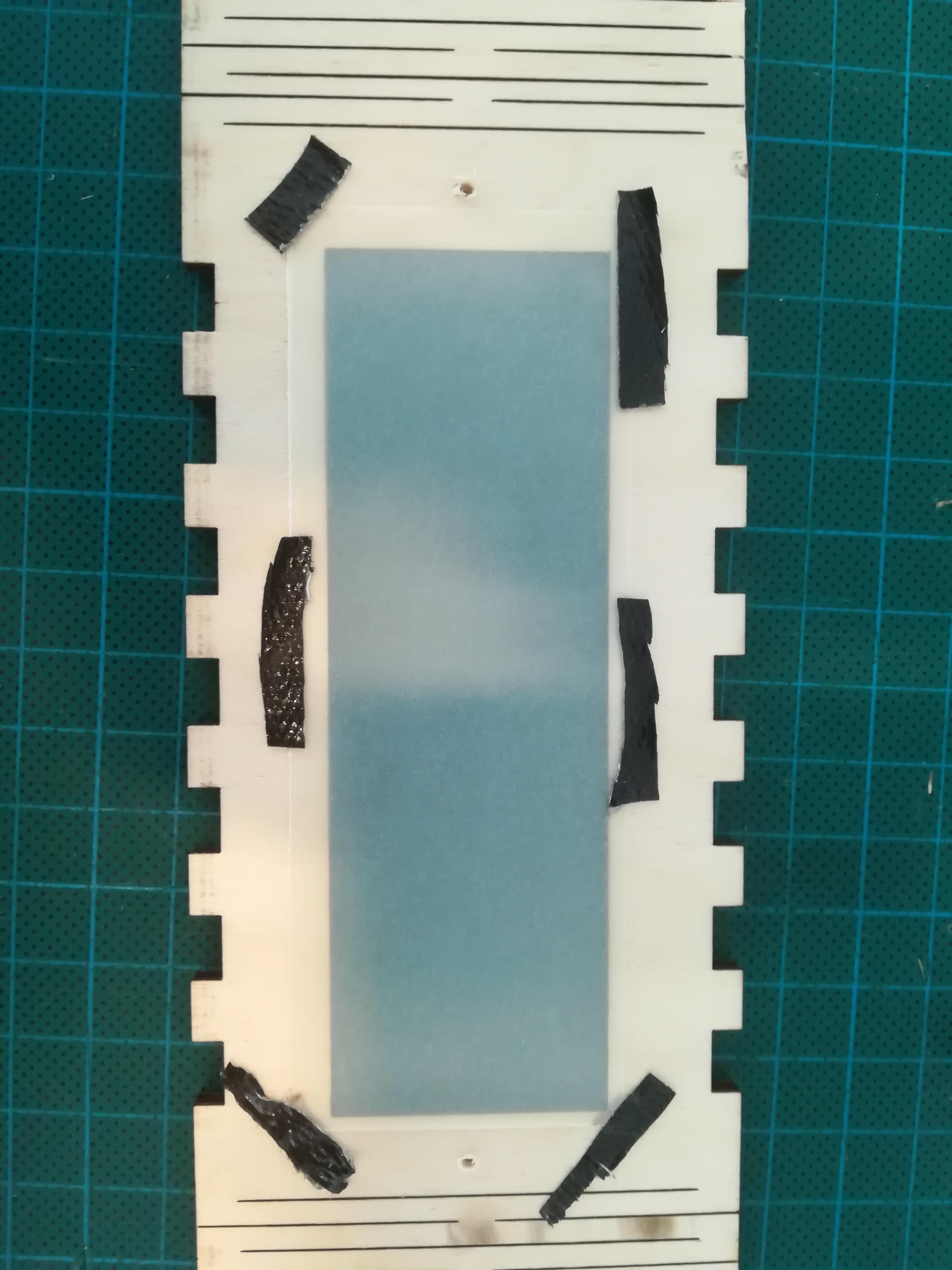
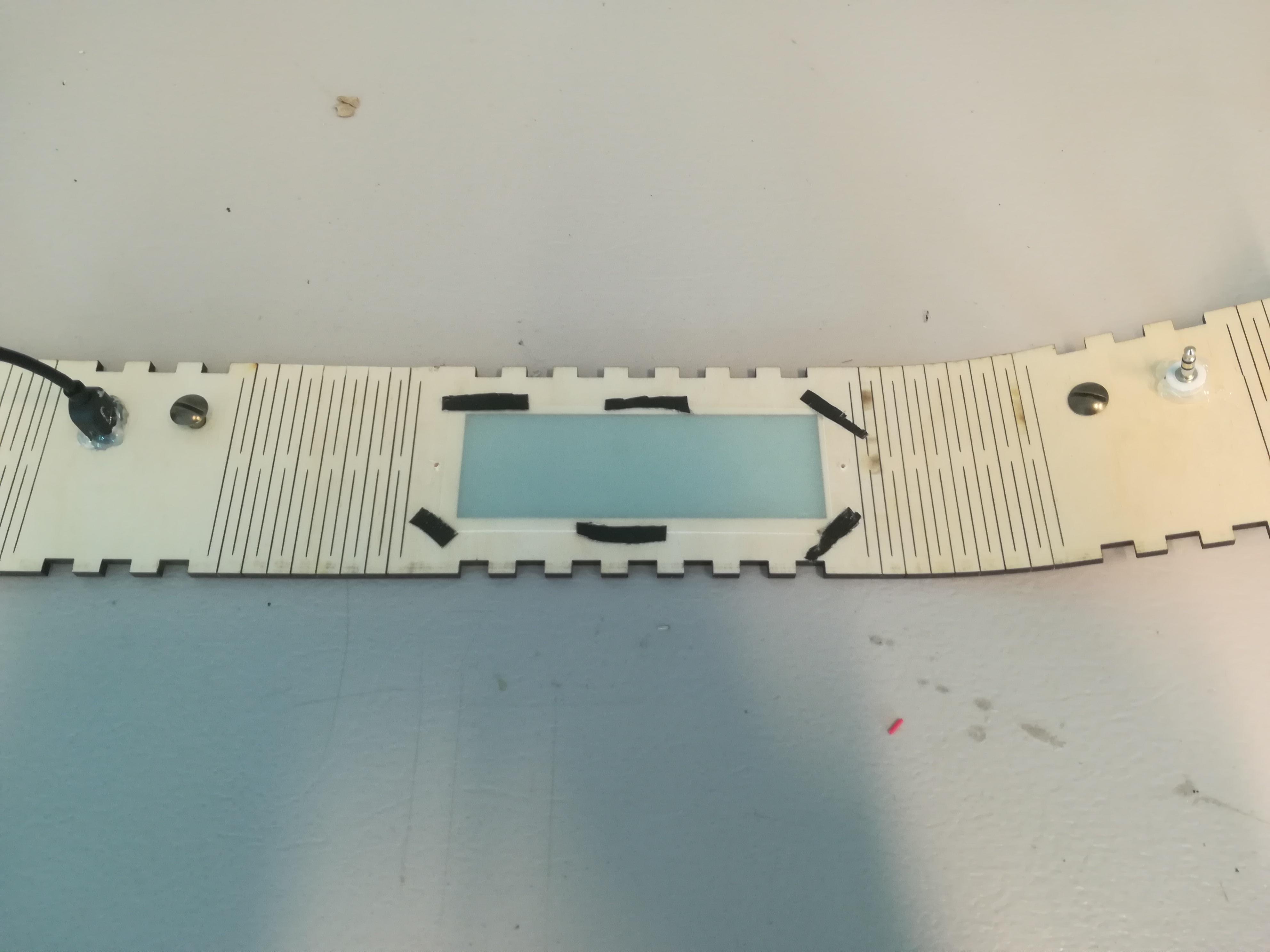
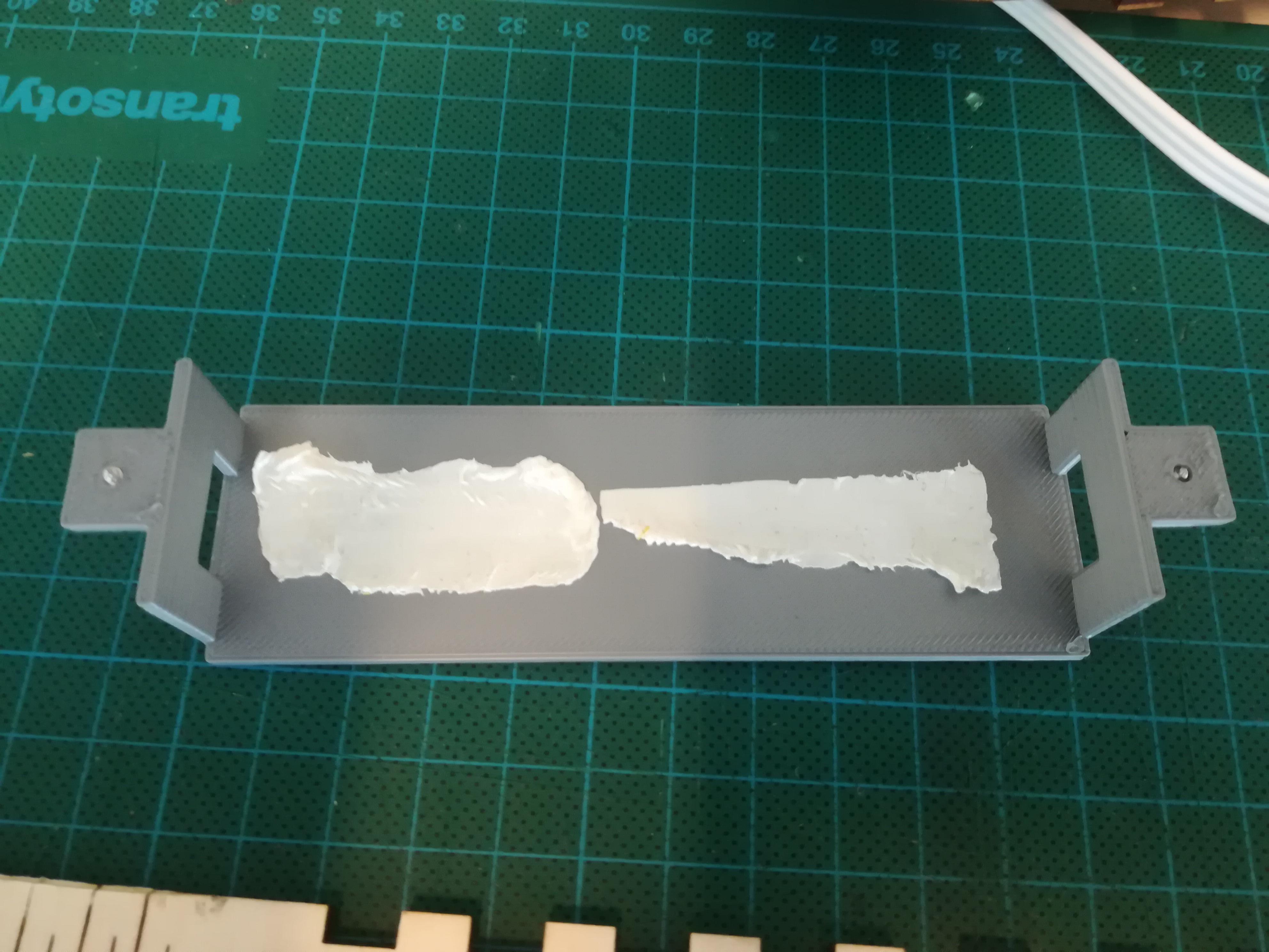
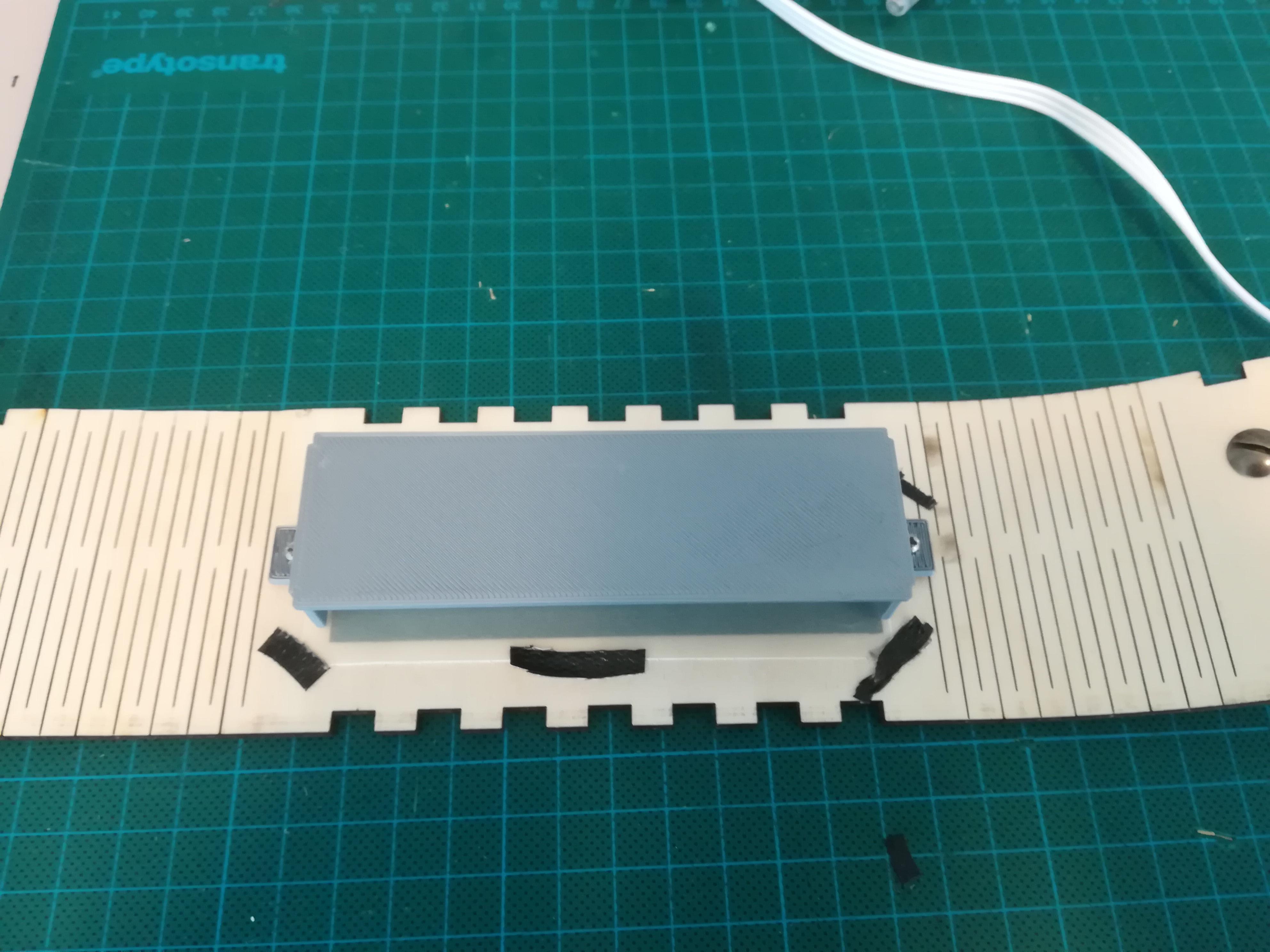
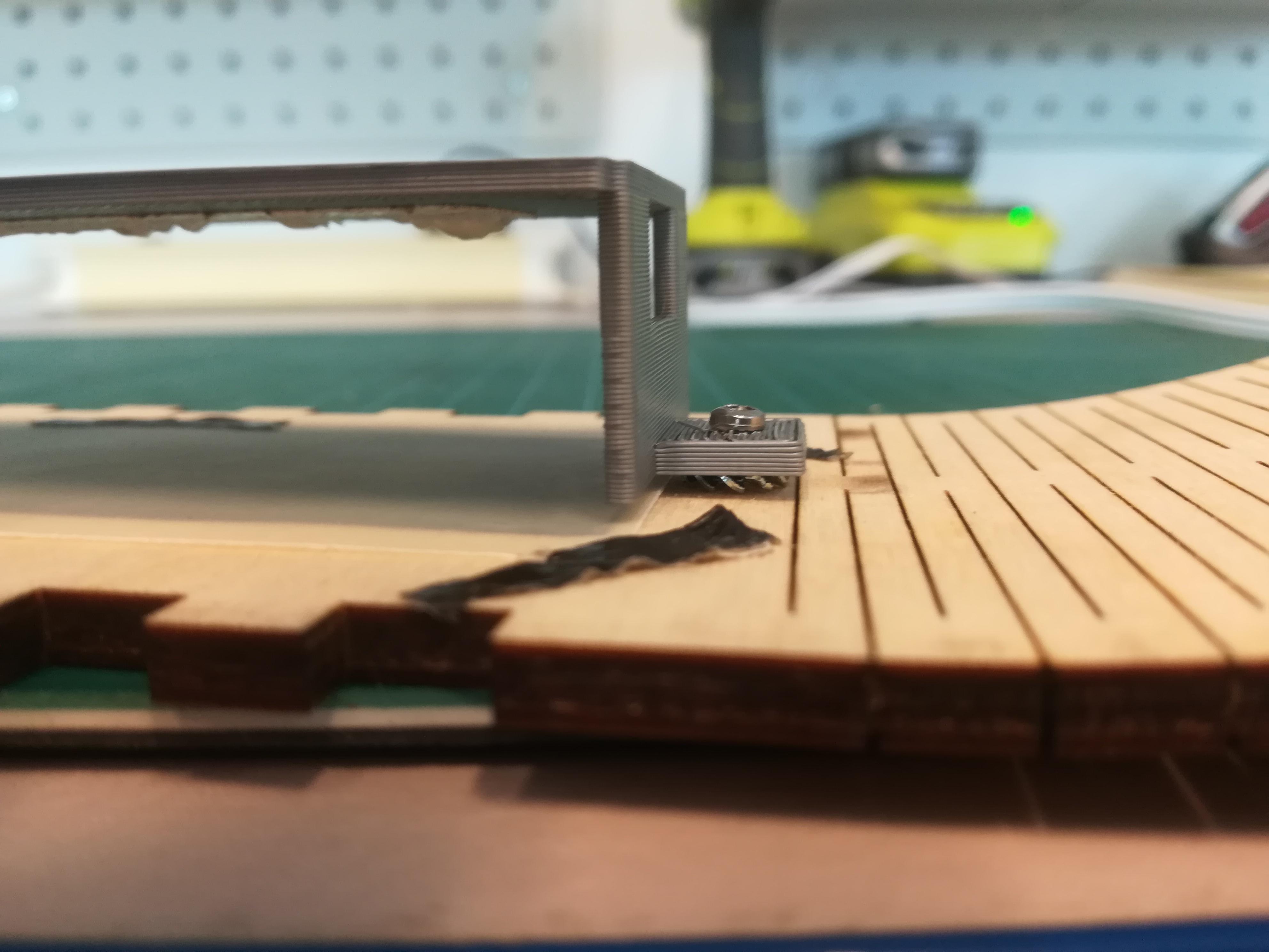
Glue the acrylic sheet to the ribbon as shown in the picture. If you want the light to be dimmed you can tape som parchment paper (or other matte material) onto the acrylic window, or alternatively use sandpaper to sand down the acrylic.
With a gluegun, glue the USB port for charging in the hole intended for this (the one with a battery engraved besides it). Then glue the EMG sensor 'jack' in the round hole, which is on the opposite side than the USB port.
Optional: if you want a leather strap attatched, now will be a good time to mount the buttons, as this will be challenging one the technology gets in the way.
Put dobbelsided tape on the 3D printed LED bridge, this is where the LED strip will be sticked onto later. With small screws and maybe some washers, mound the LED bridge onto the ribbon.
Step 3: Assembling the Casing - Front Panel
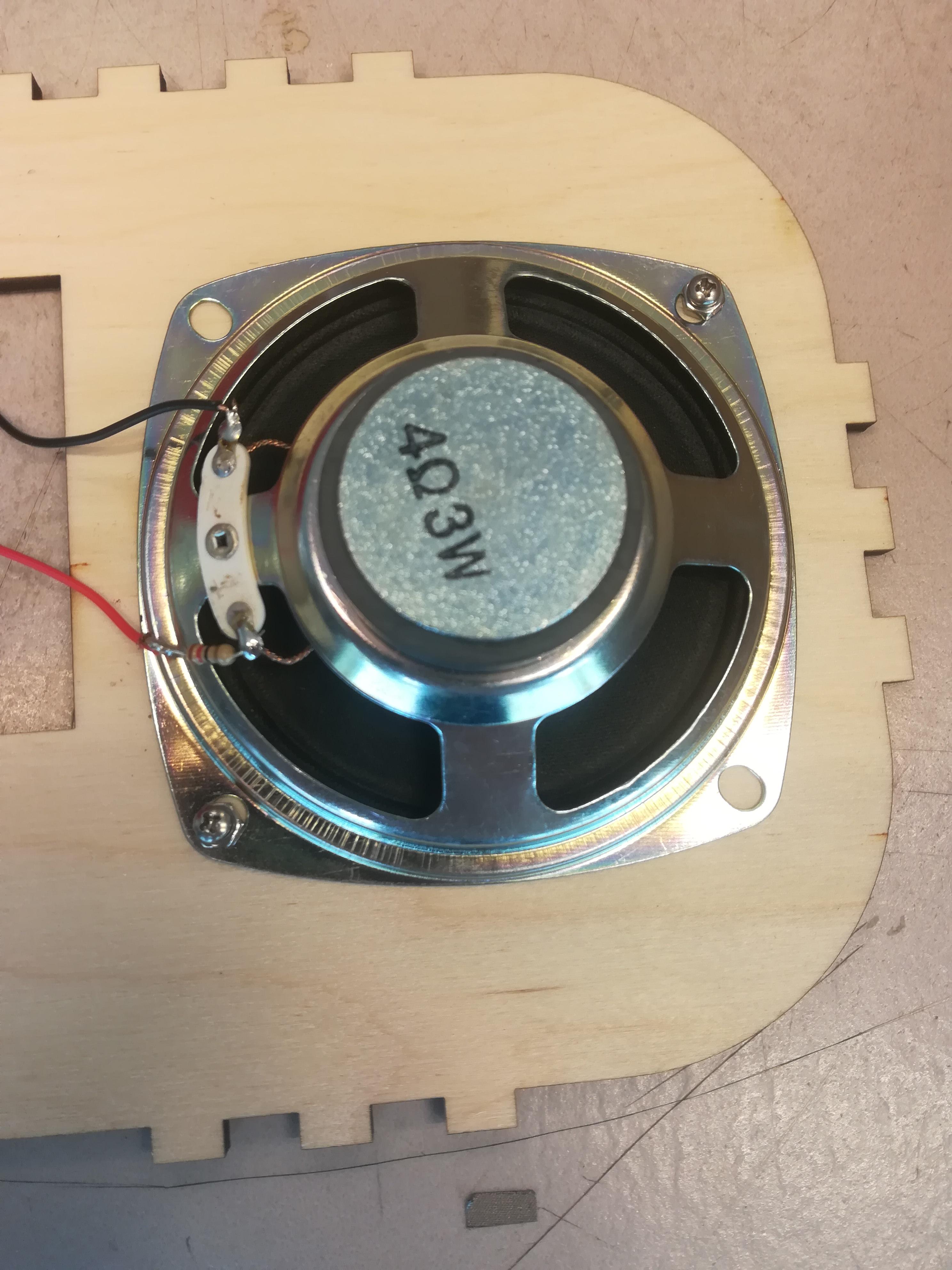
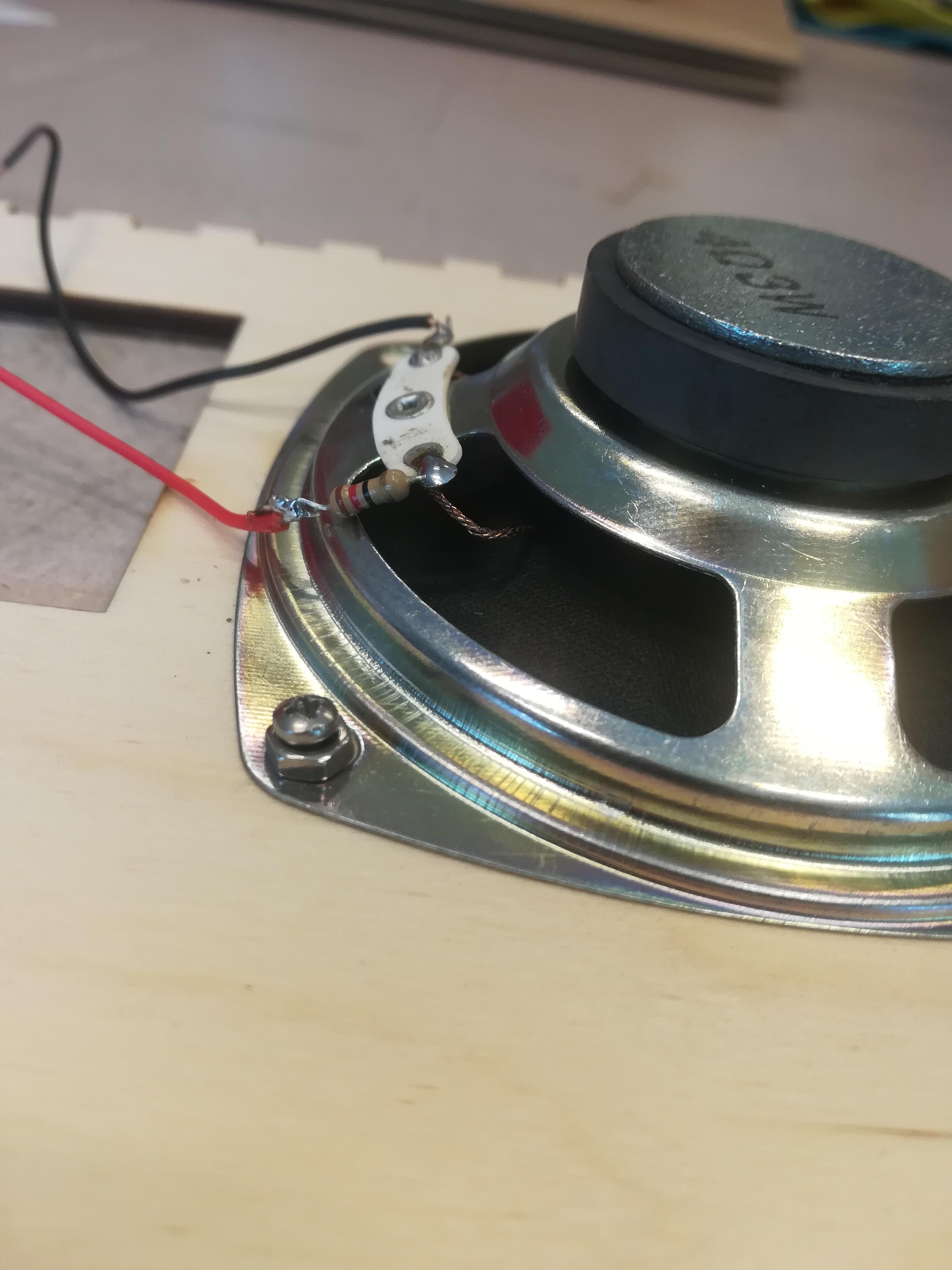
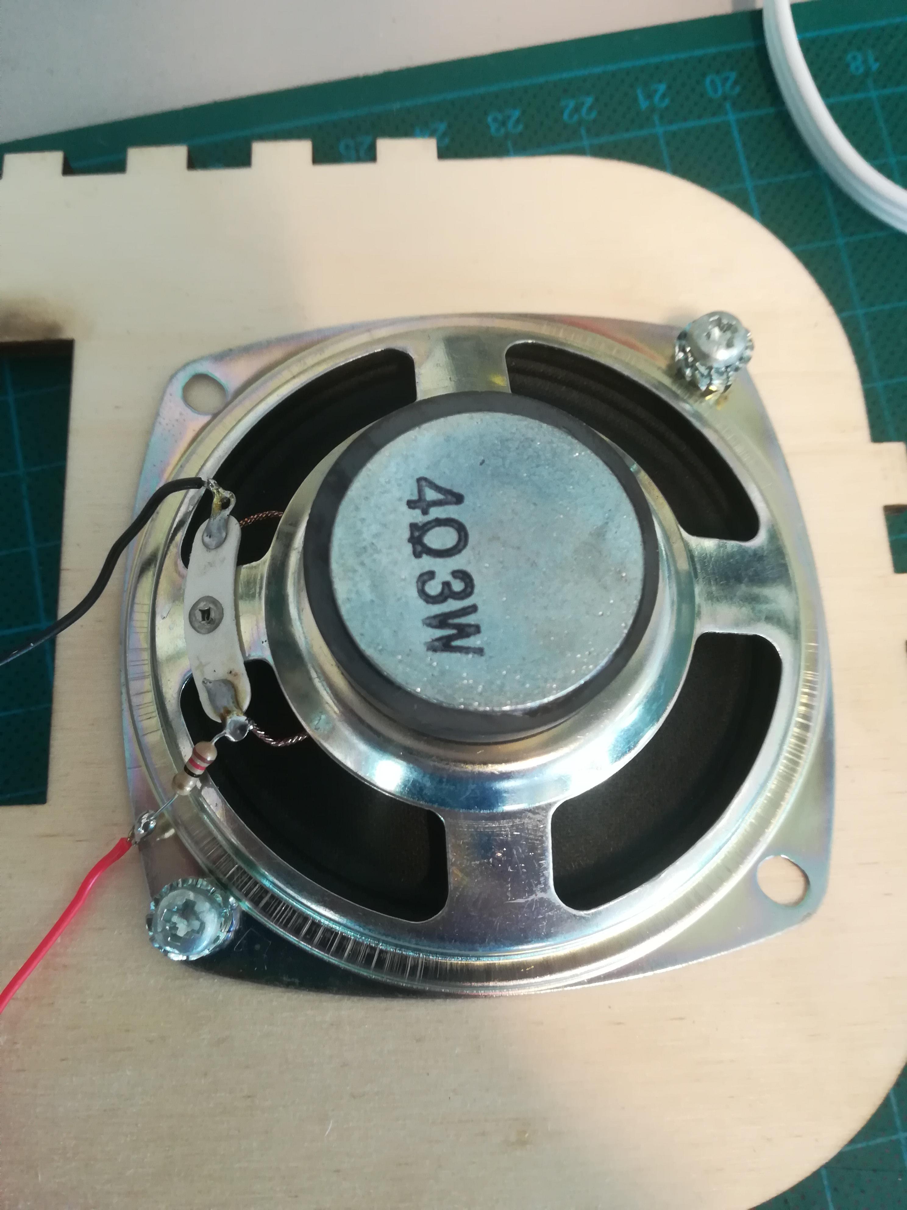
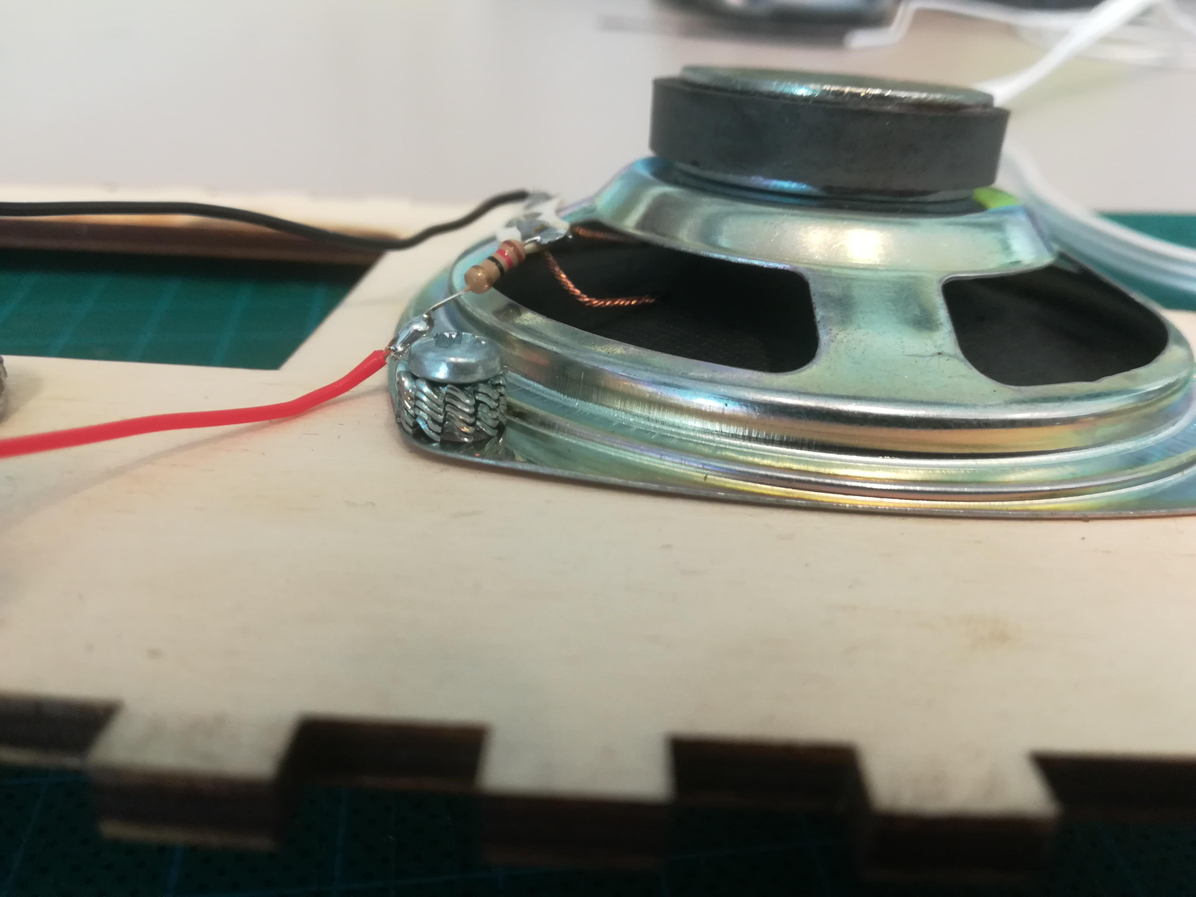
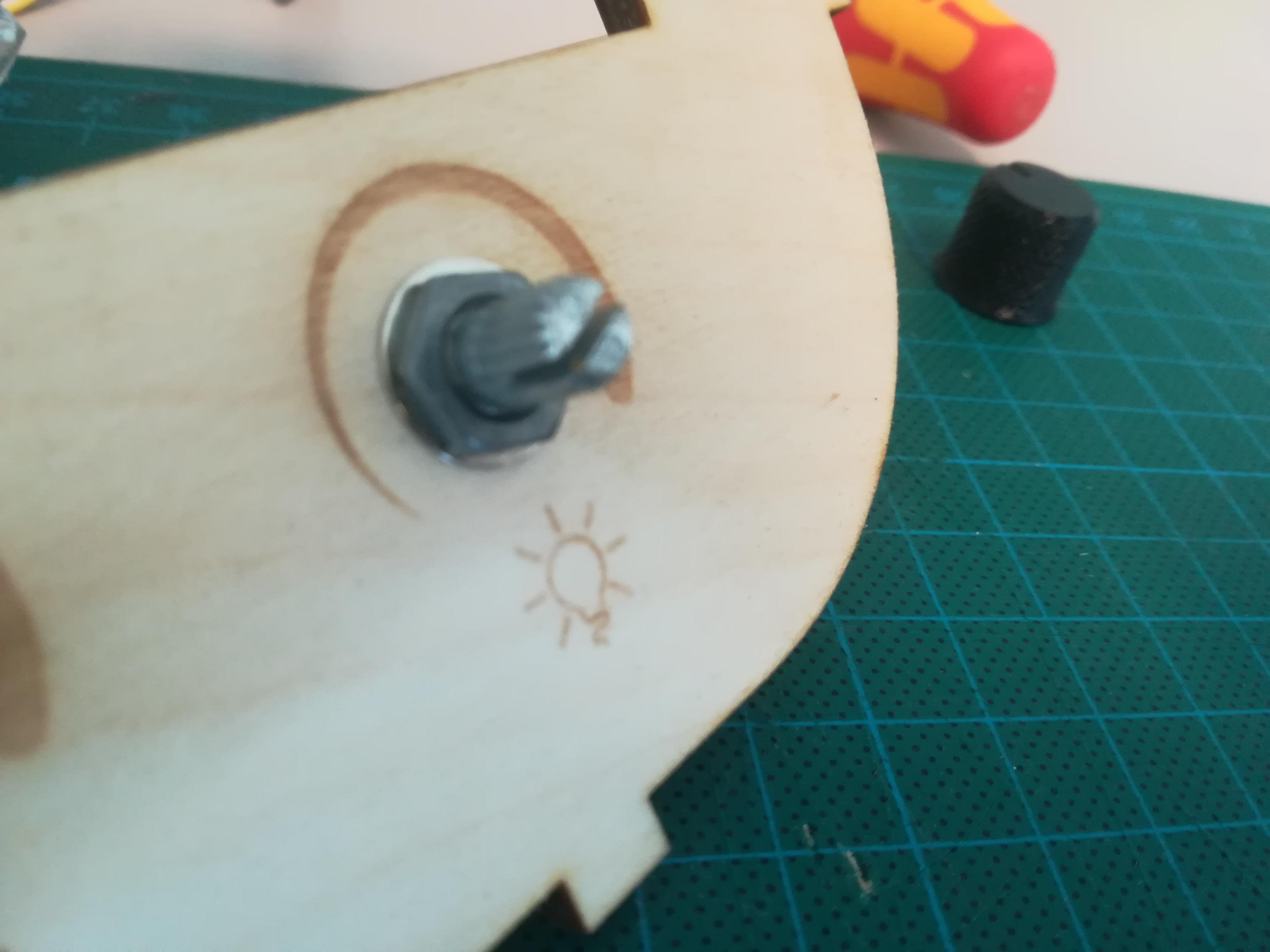
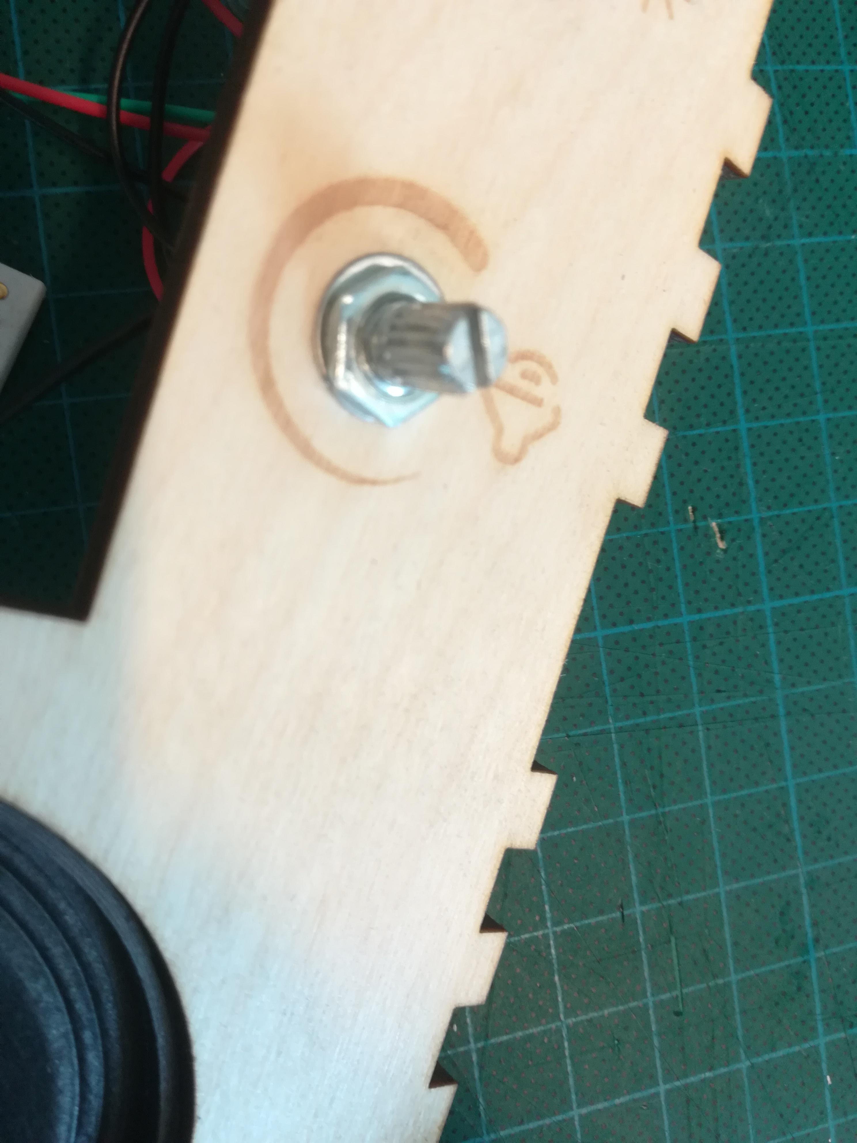
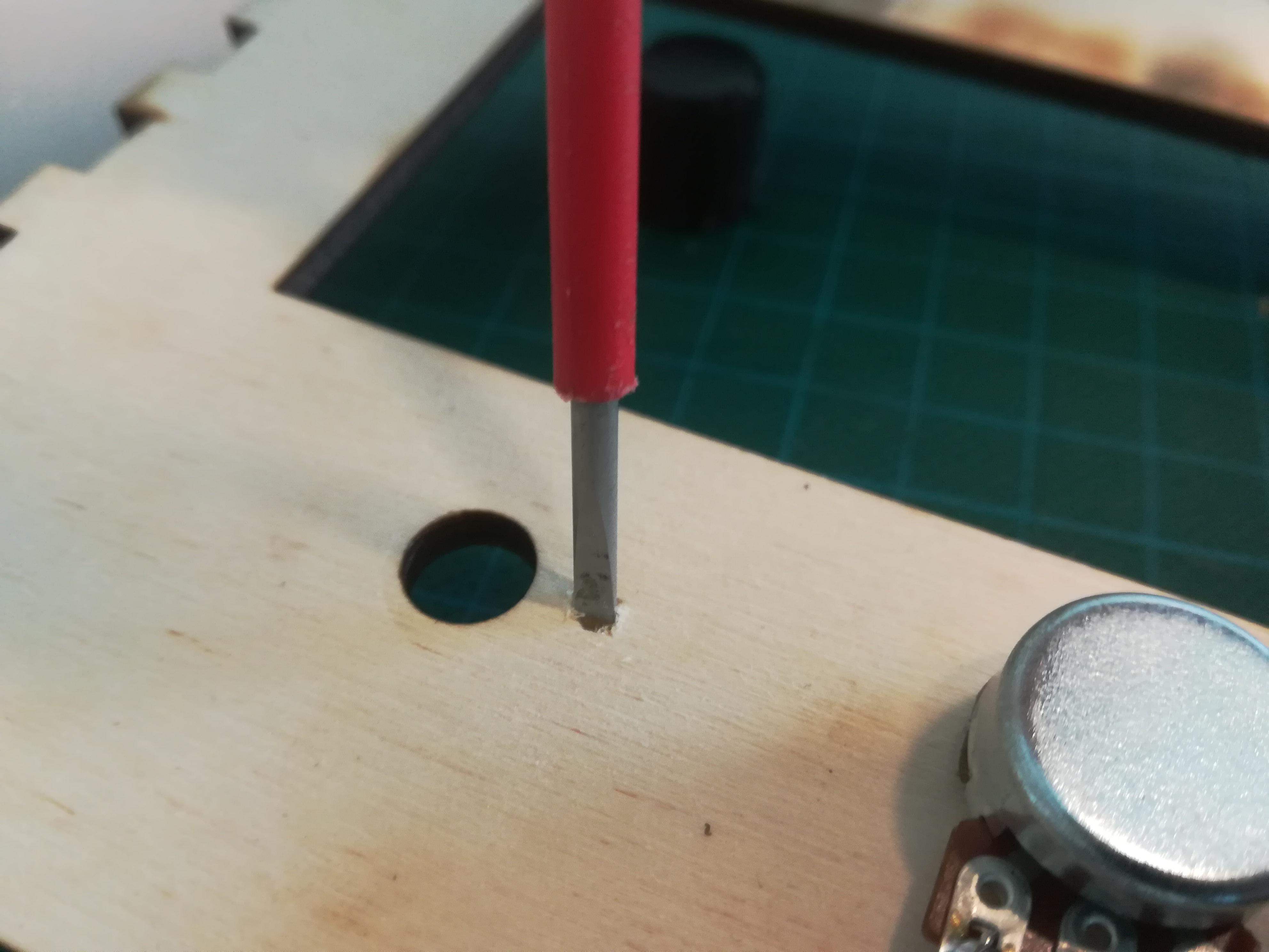
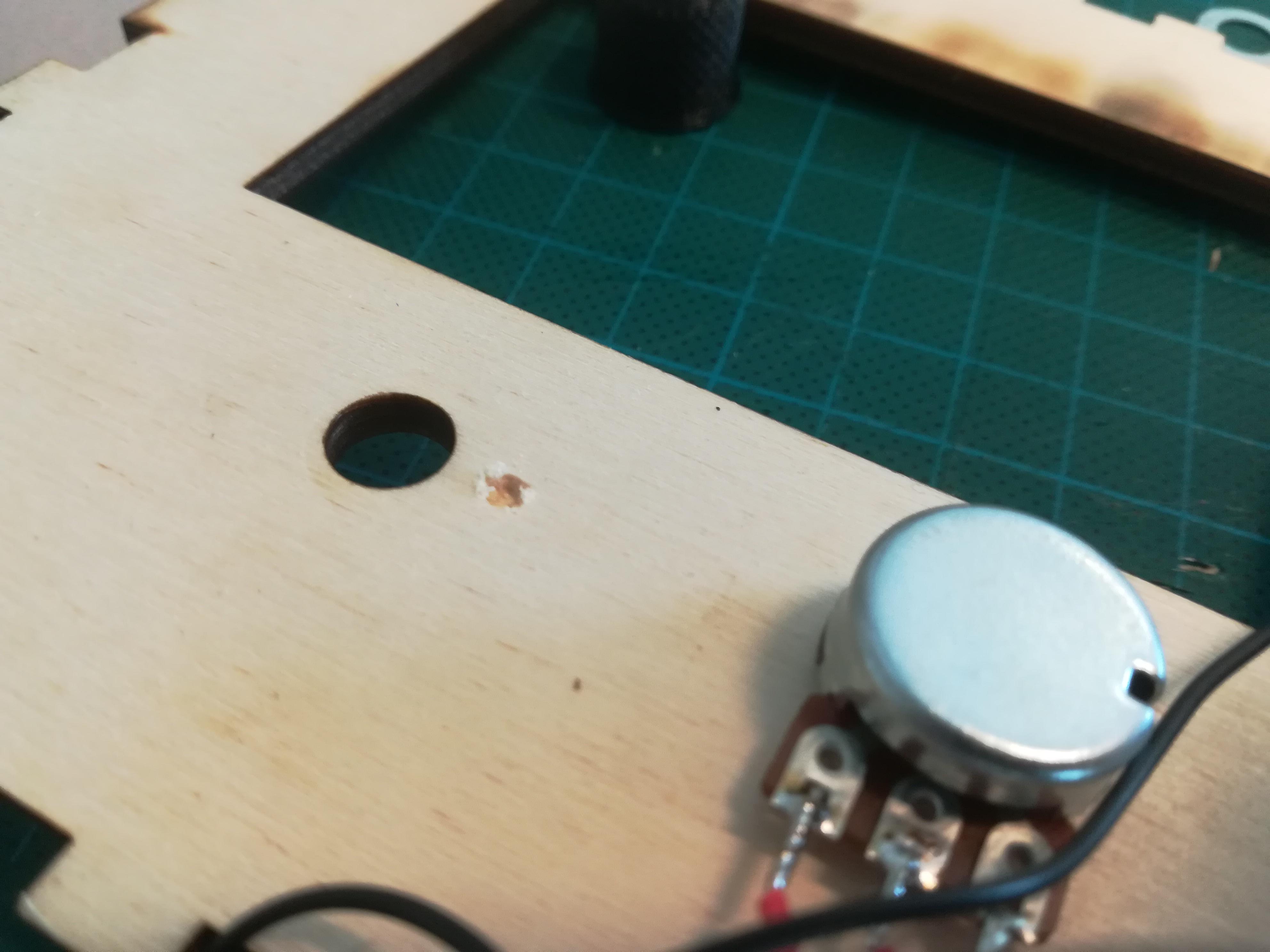
With small screws, mount the speaker onto the front panel. Solder wires and a resistance onto the speaker. Make sure the wires of the speaker point towards where the screen will be.
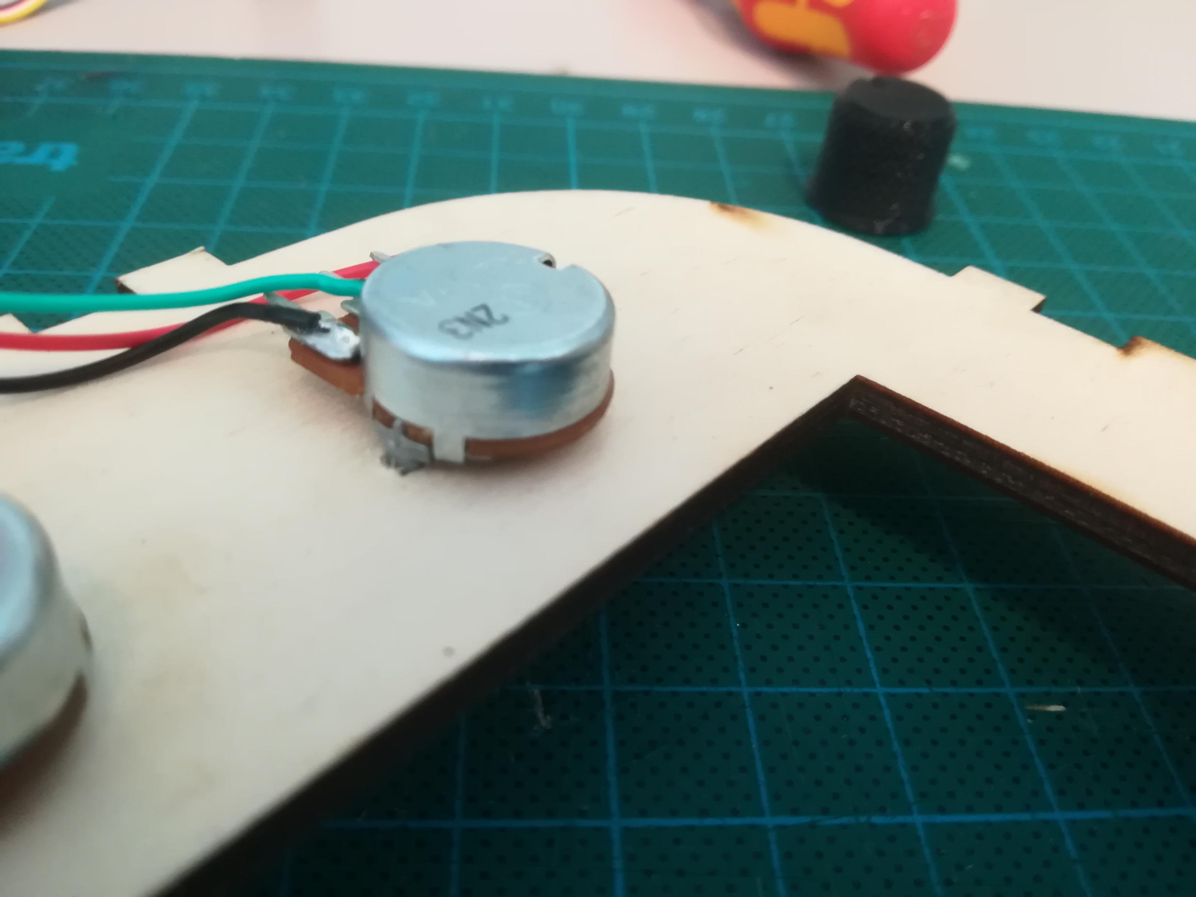
Mount the potentiometers. 1K for sound and 100K for light. Tighten with a wrench.
(with some potentiometers, there's a little tap that you might need to make room for in the wood, as shown in the pictures)
Step 4: Assembling the Casing - Glue Front and Ribbon
Now that the ribbon and front panel is prepared, you can glue them together with wood glue. Put some glue where the joints meet (Tip: use a paintbrush for this for less mess) but wait with the ribbon ends till the technology is put it
Use clamps to hold everything in place while letting the glue dry.
Step 5: Preparing the Technology - Raspberry Pi
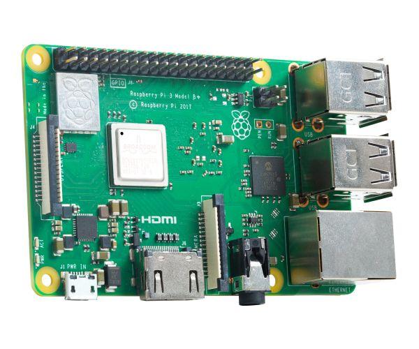
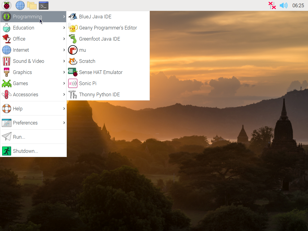
Flash a micro SD card with an operating system
Insert the SD card into your Raspberry Pi
Boot up the Pi, connect it to wifi, and download these software: Processing, Arduino IDE and OpenData
Libraries: [to be added]
Put the code onto the raspberry pi either through a git request in the terminal or by USB.
Step 6: Assembling the Technology - Trinket
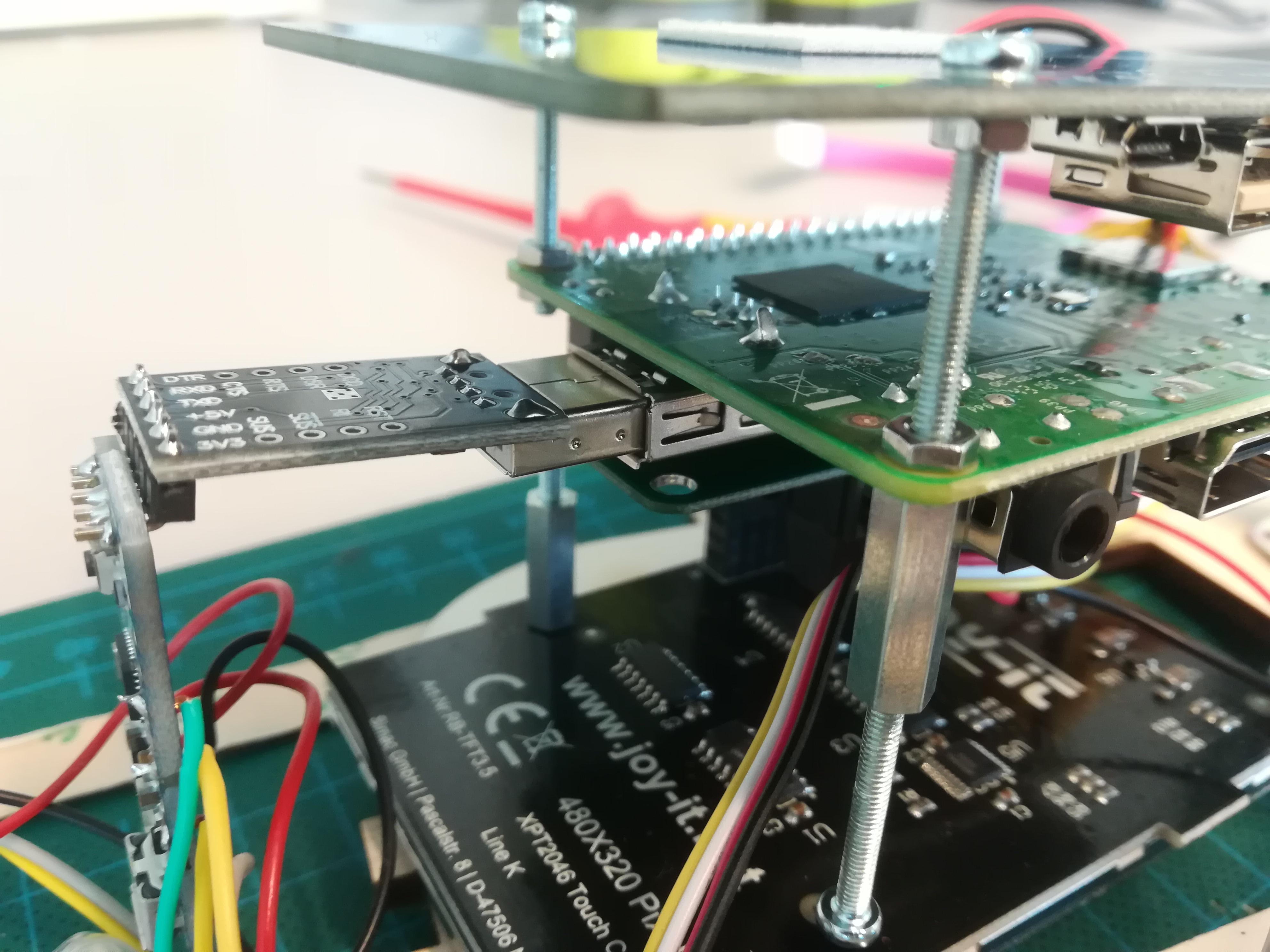
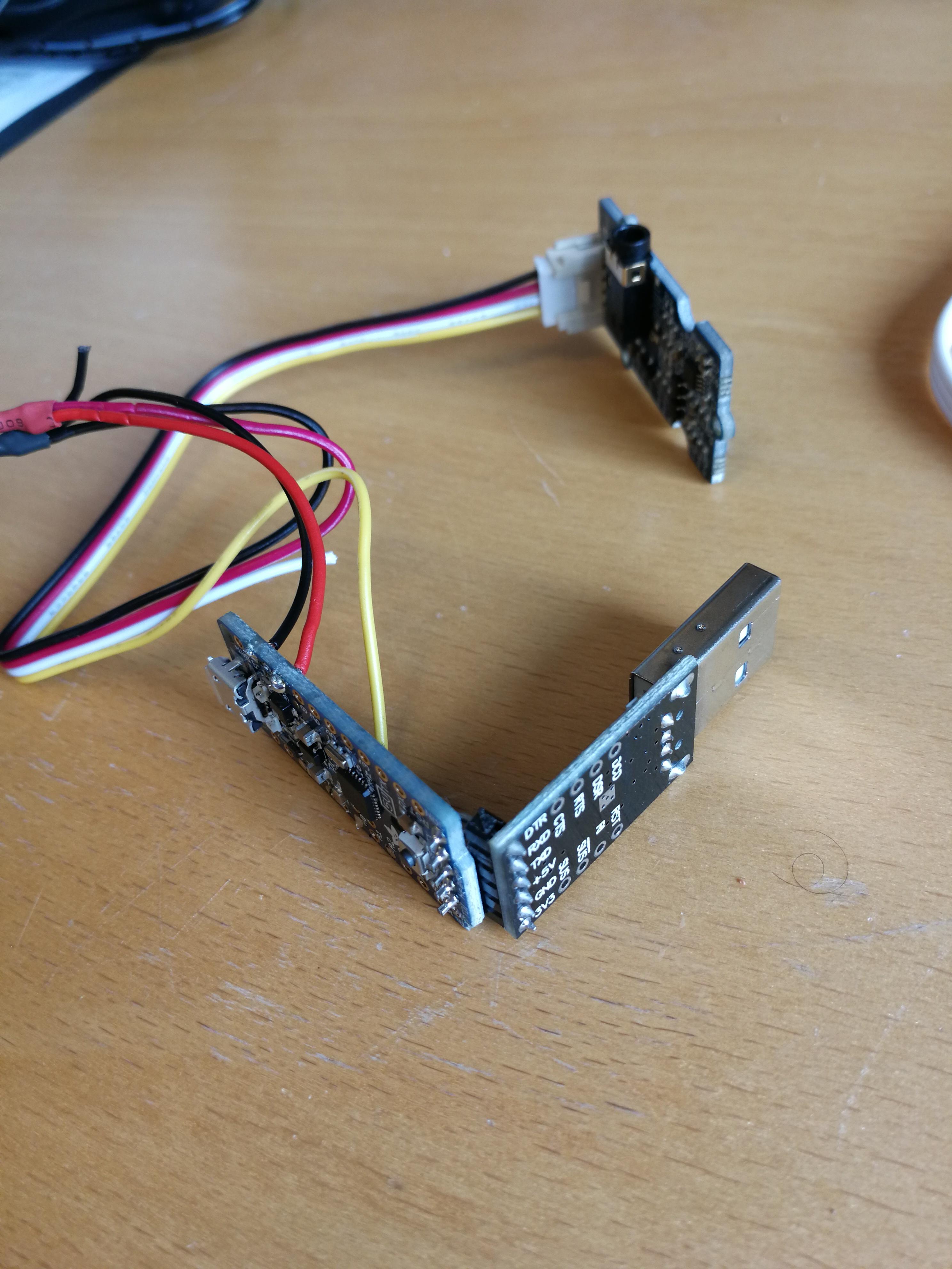
The Arduino pro trinket is receiving the data from the EMG sensor as well as controlling the LED lights. So we need to solder some wires between these things.
Other than that, because the raspberry pi doesn't come with a serial connection, we would have to do a workaround by soldering a serial USB onto the trinket.
Step 7: Assembling Technology - Stack of Boards
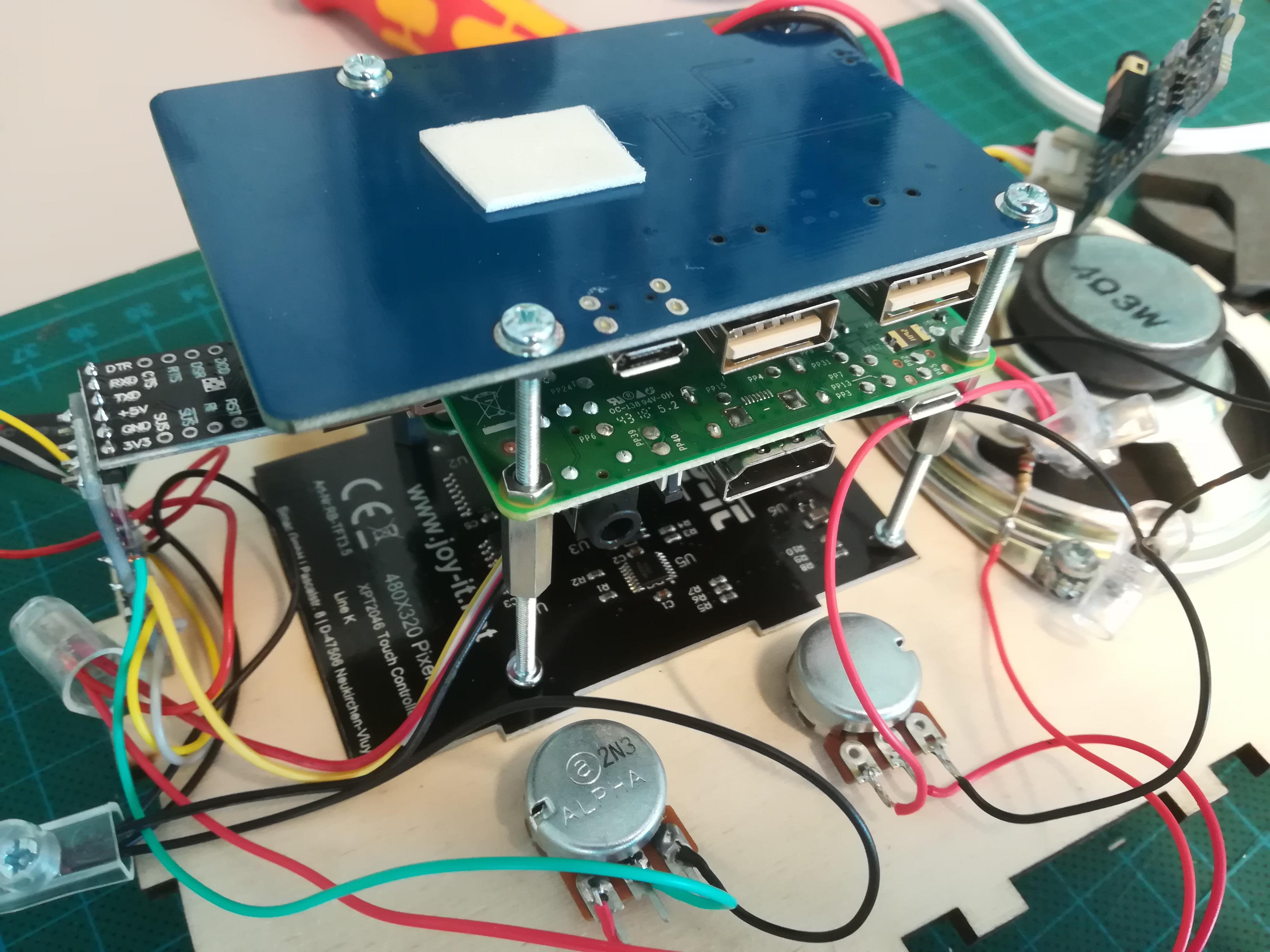
With bolts and nuts, create a stack of your boards in this sequence:
- Power supply board
- Raspberry Pi
- Sound board
- Screen
Insert the Serial USB and trinket from previous step into the raspberry pi's USB port.
Step 8: Assembling Technology - Connecting Everything
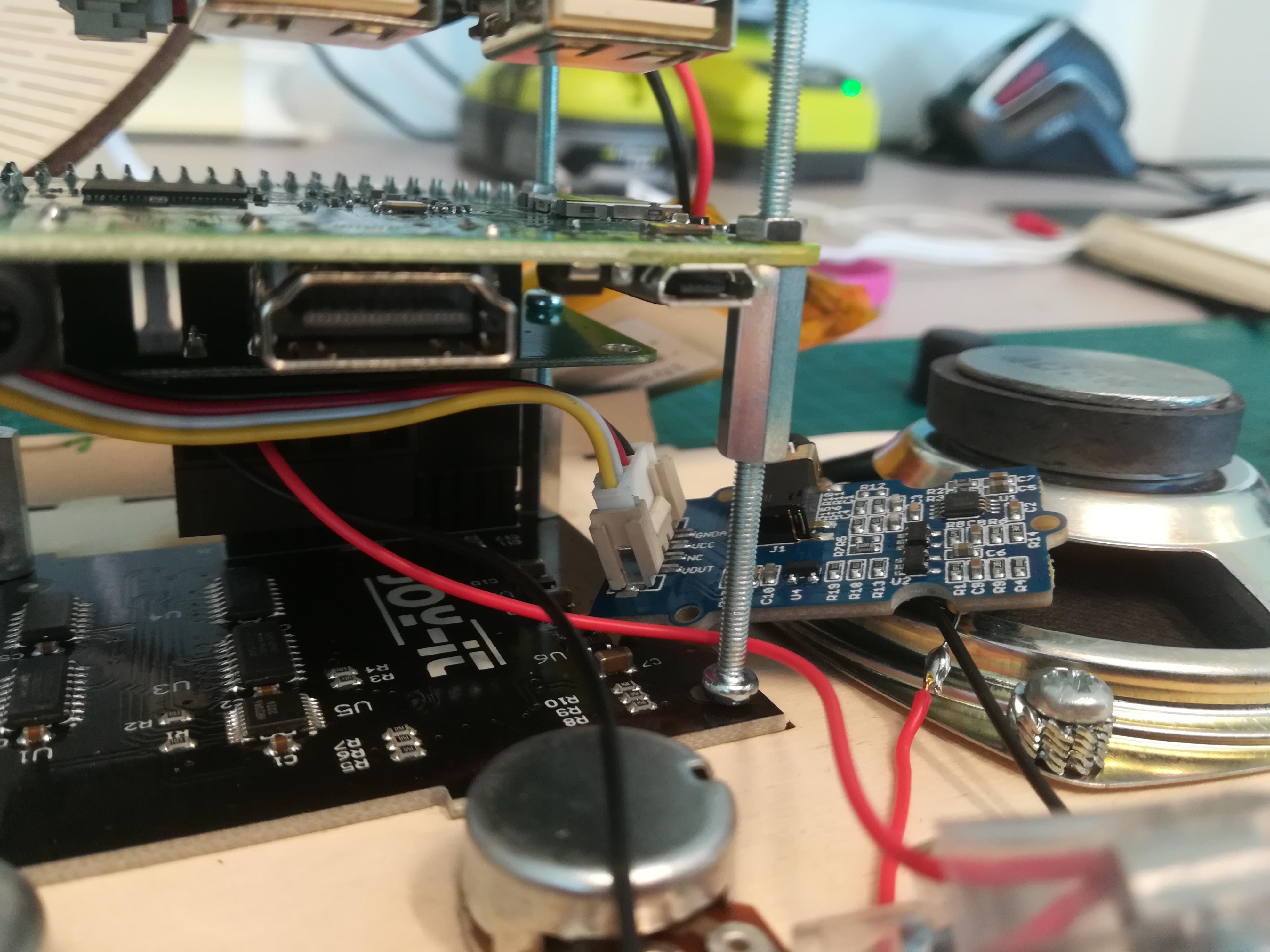
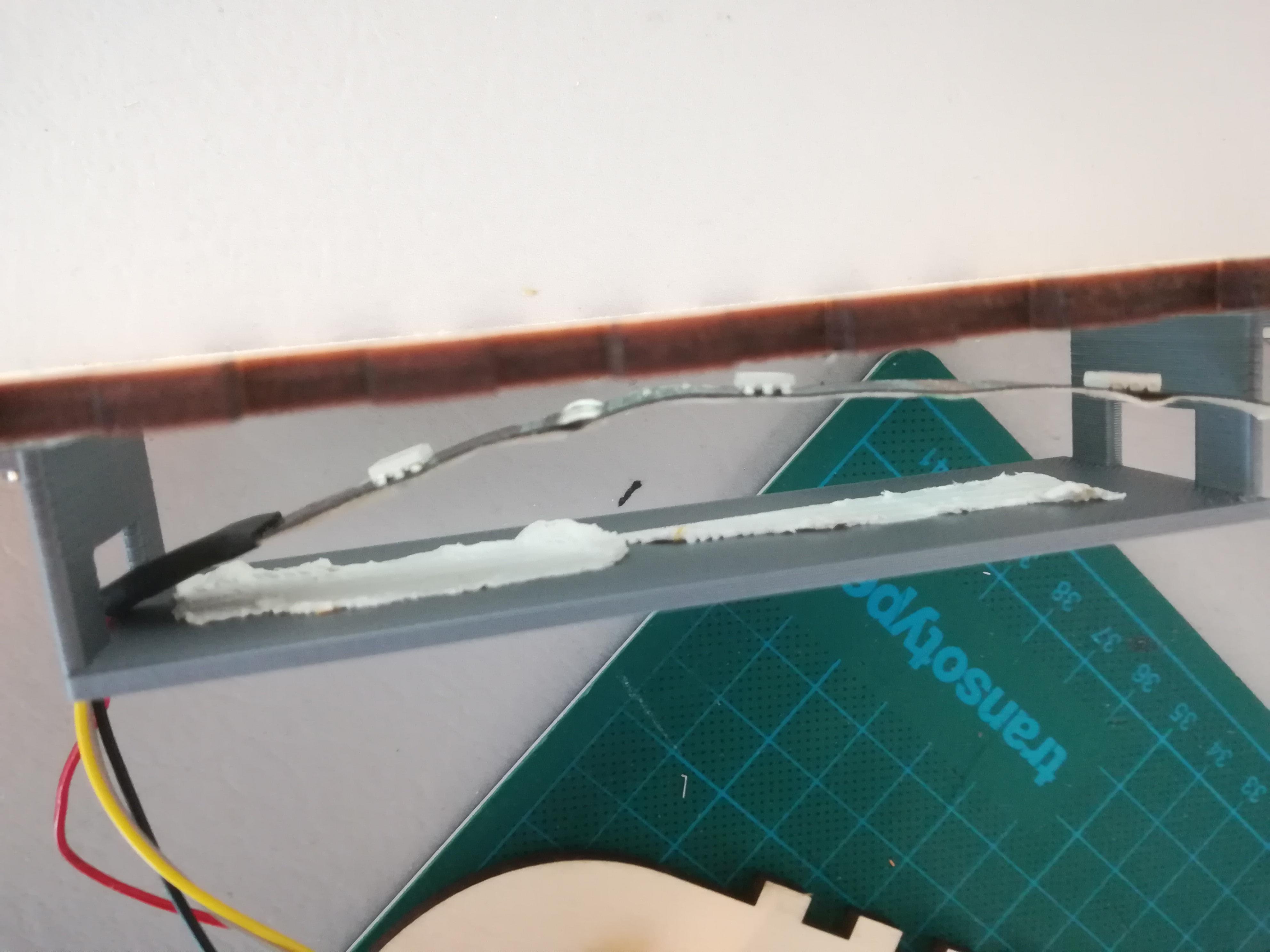
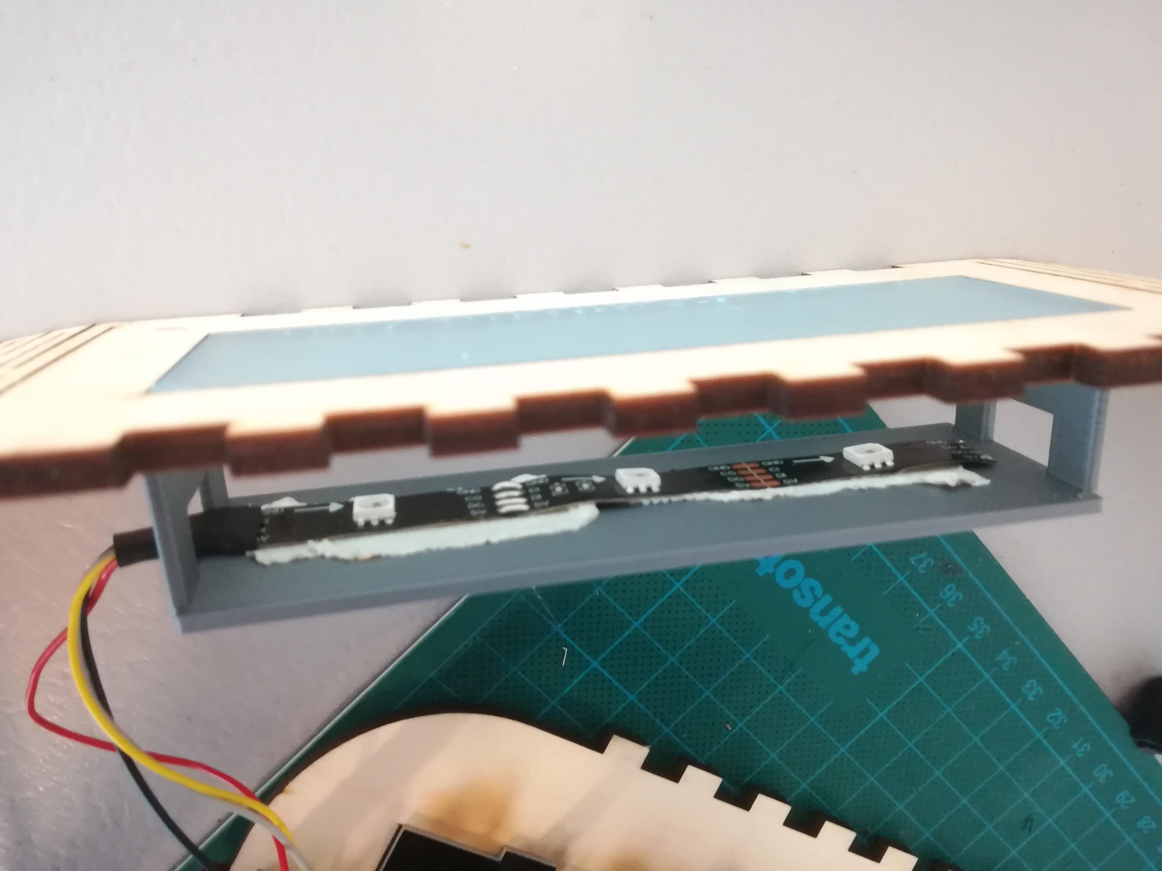
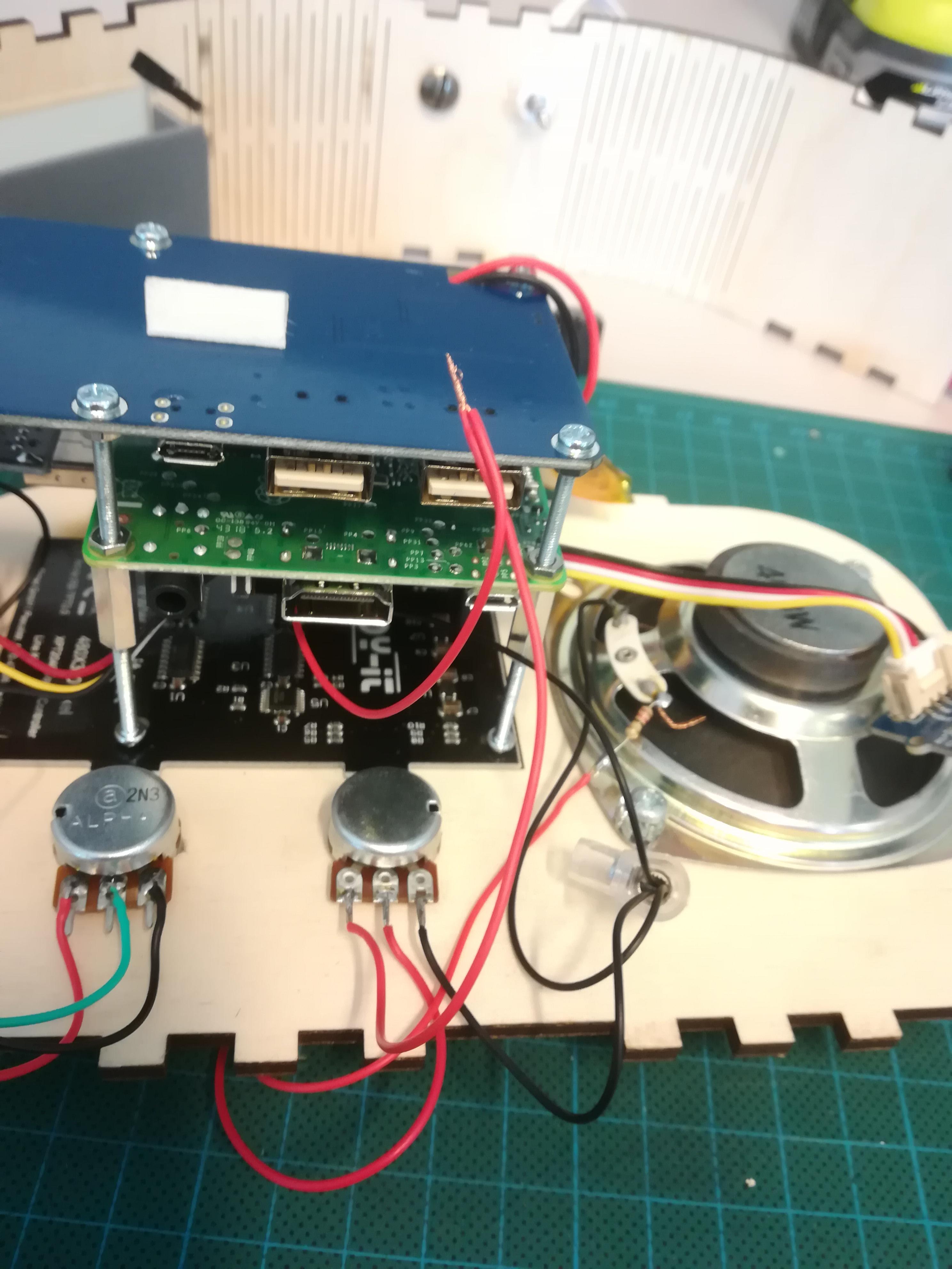
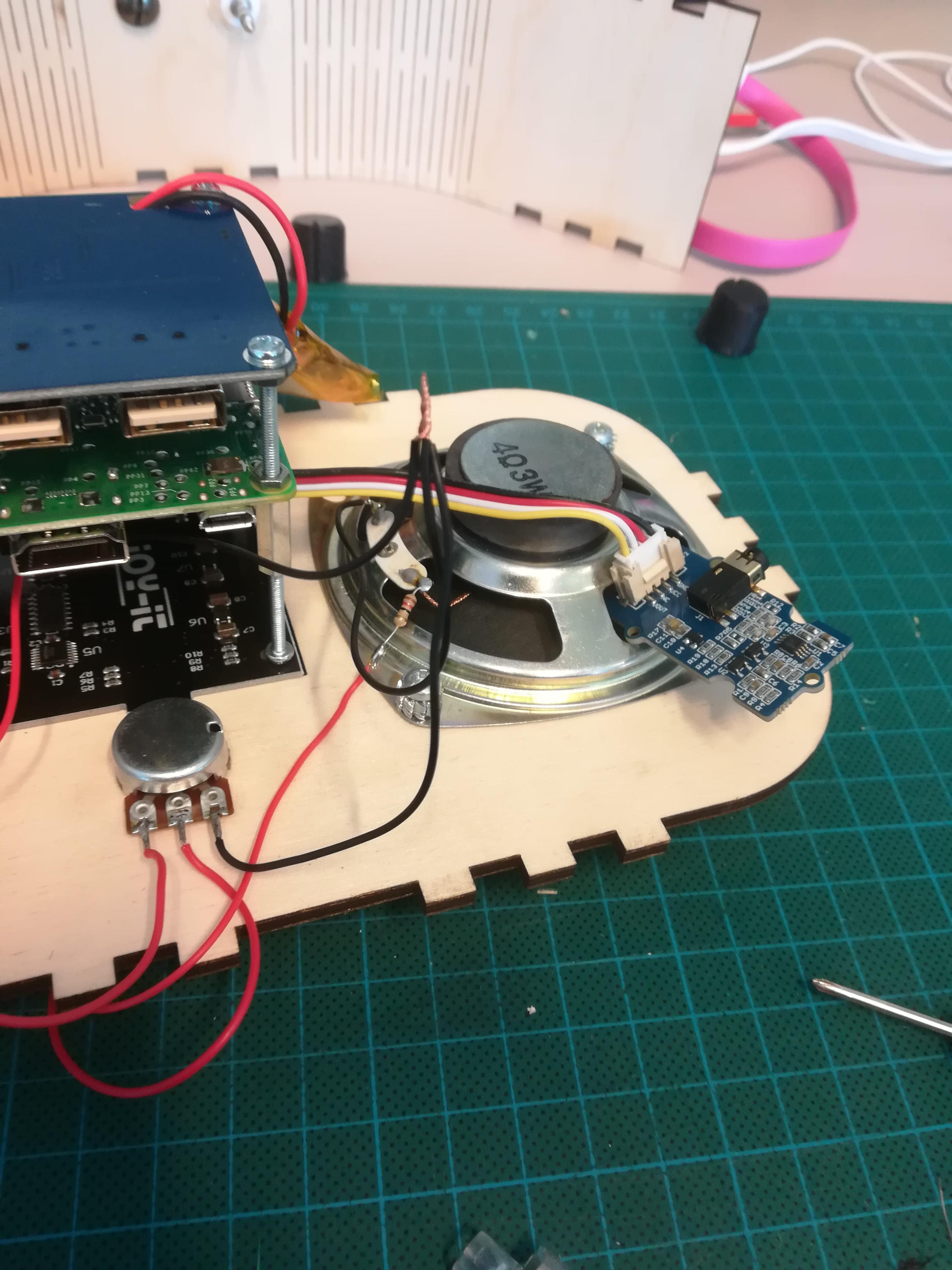
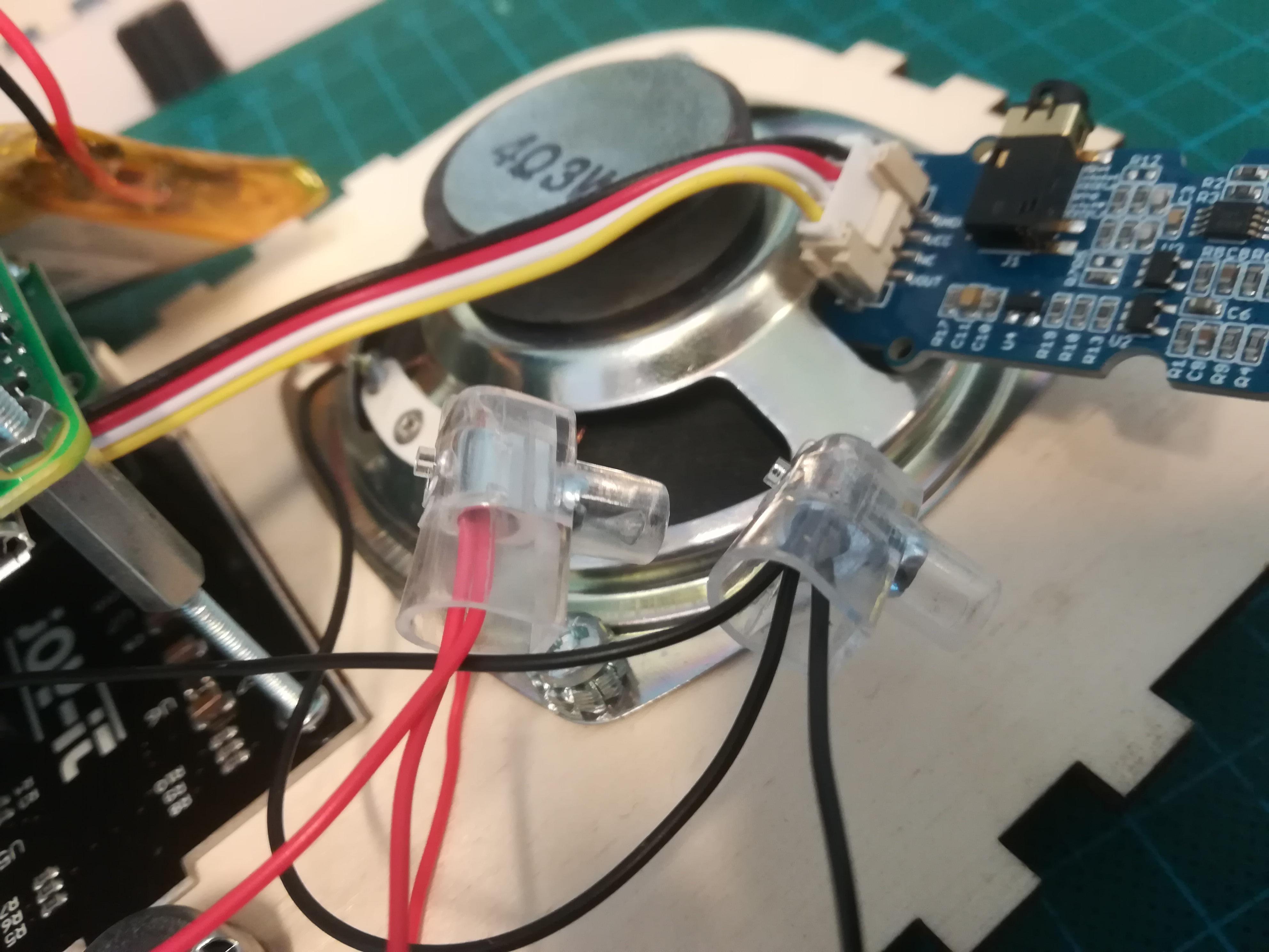
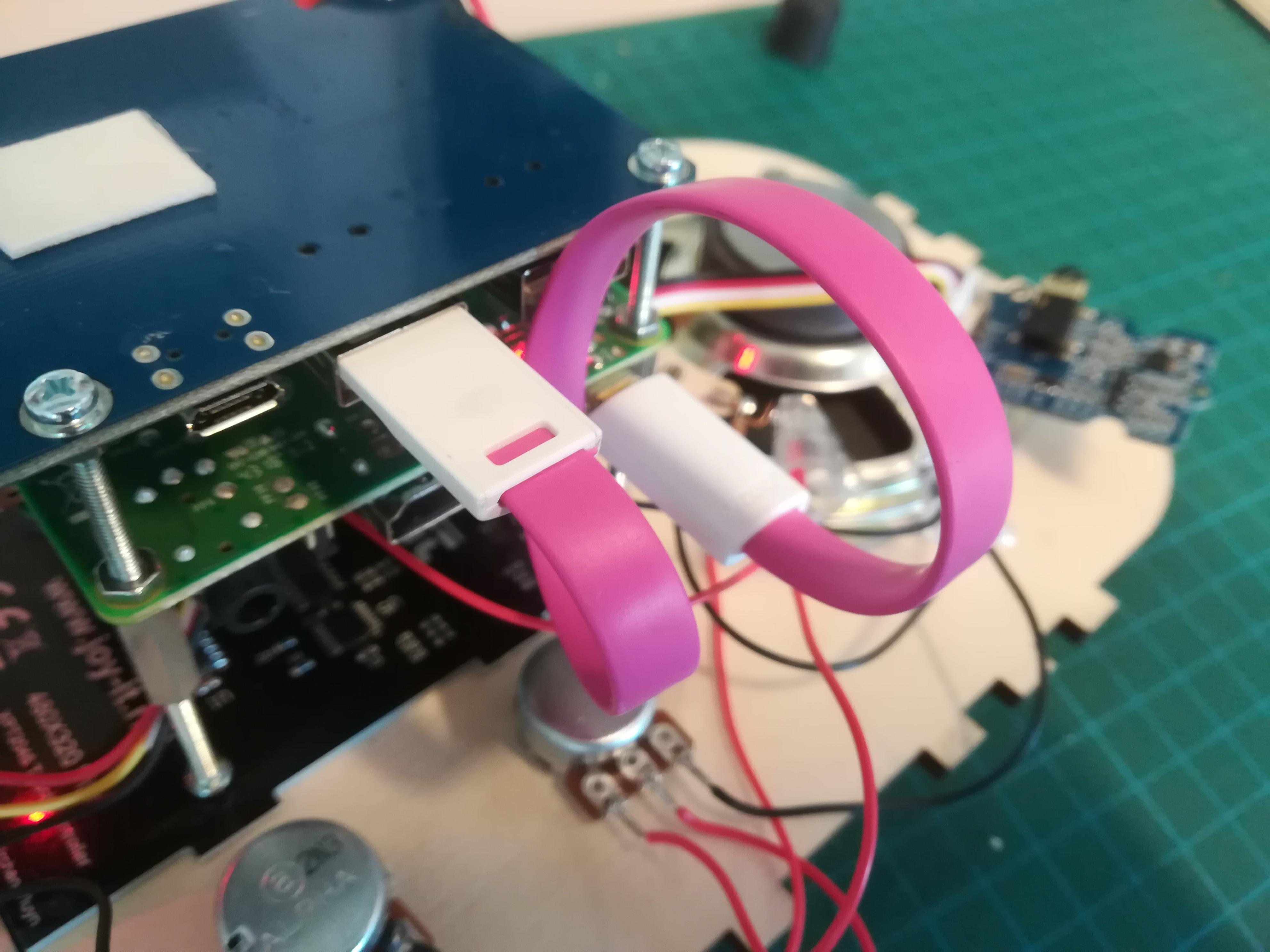
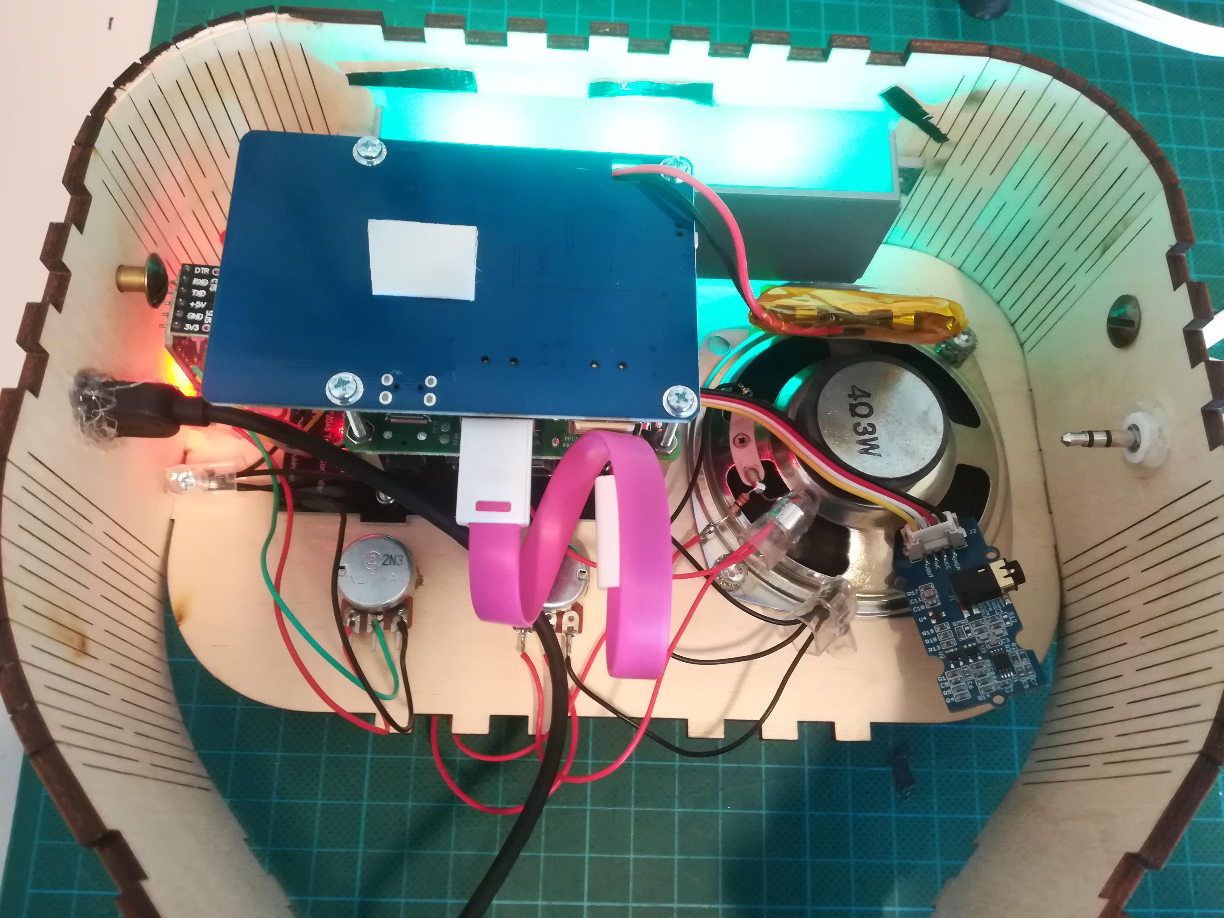
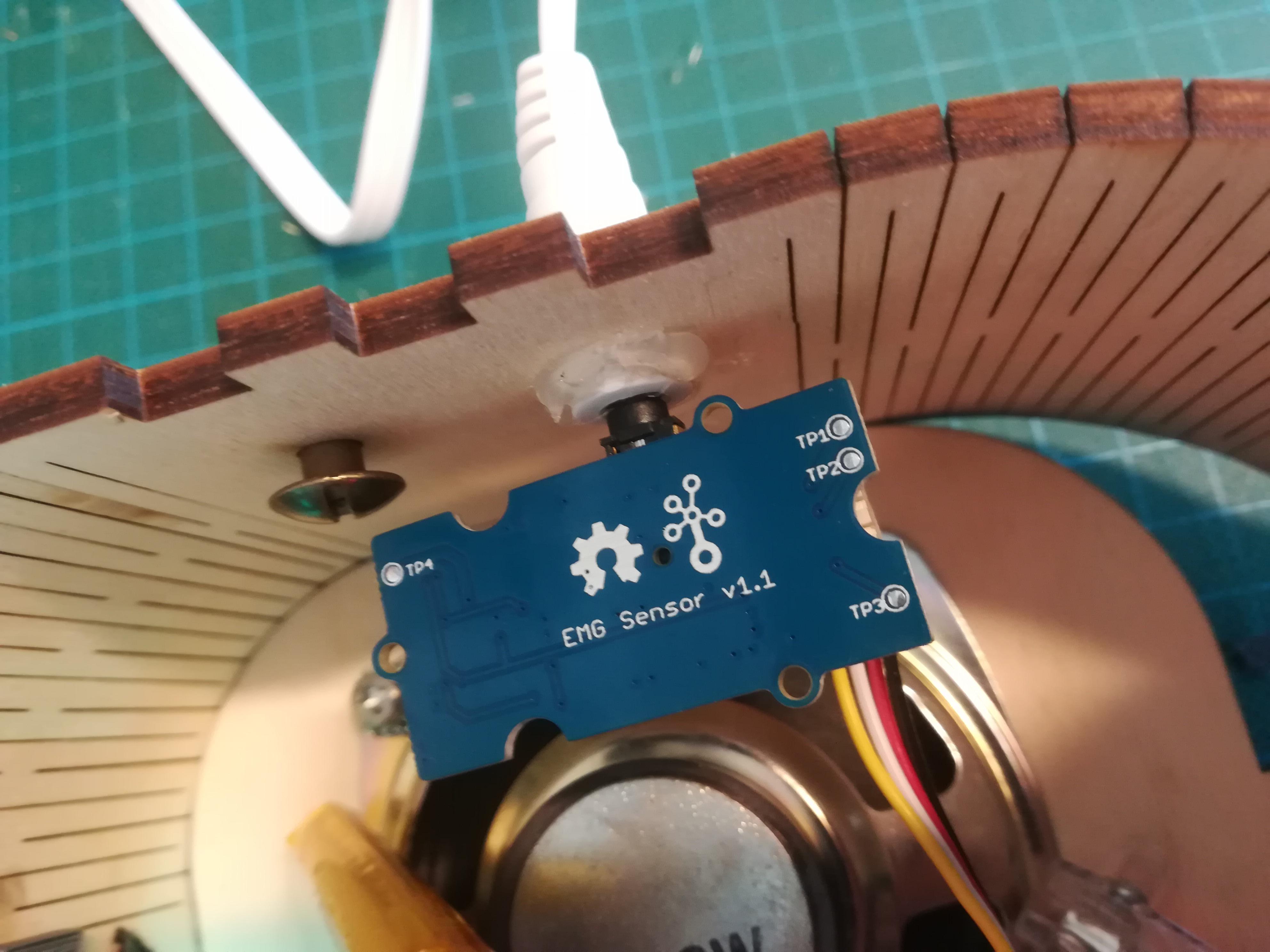
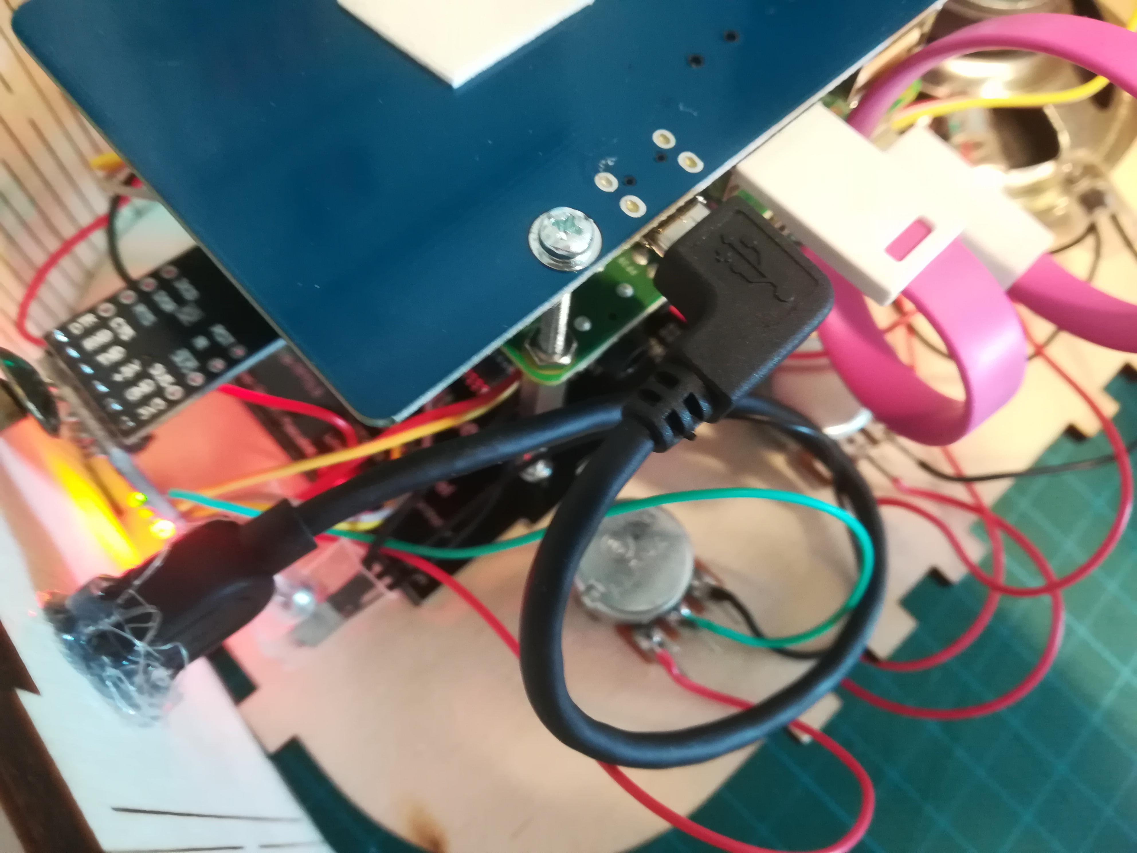
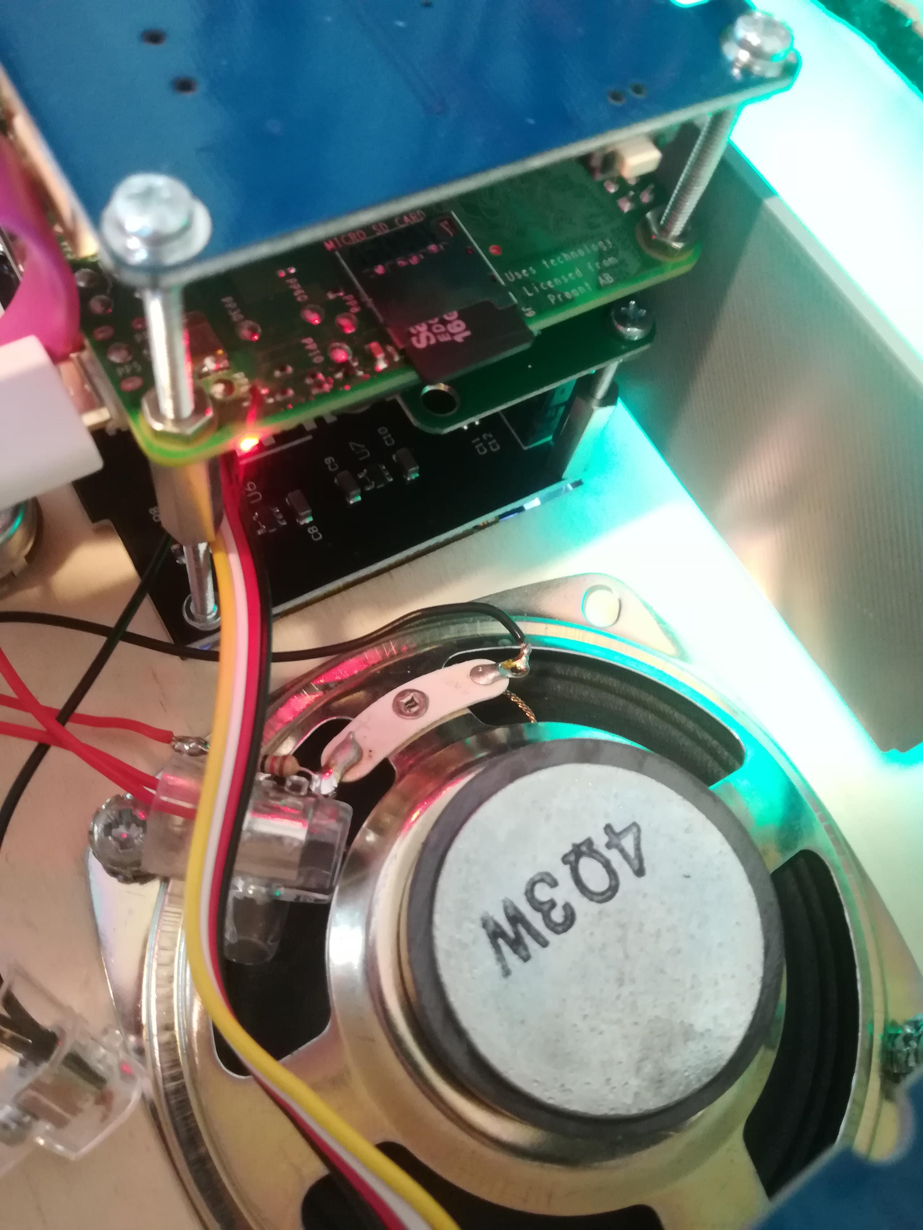
Now you can put your whole stack into the frame in the front panel where the screen should fit nice and snug.
A few things still needs to be connected and mounted.
Connect the EMG sensor board with the wires from the trinket (if you haven't already done this from step 6).
Mount the LED strip onto the bridge, where the double-sided tape is. To make it extra secure you can apply more tape onto the strip.
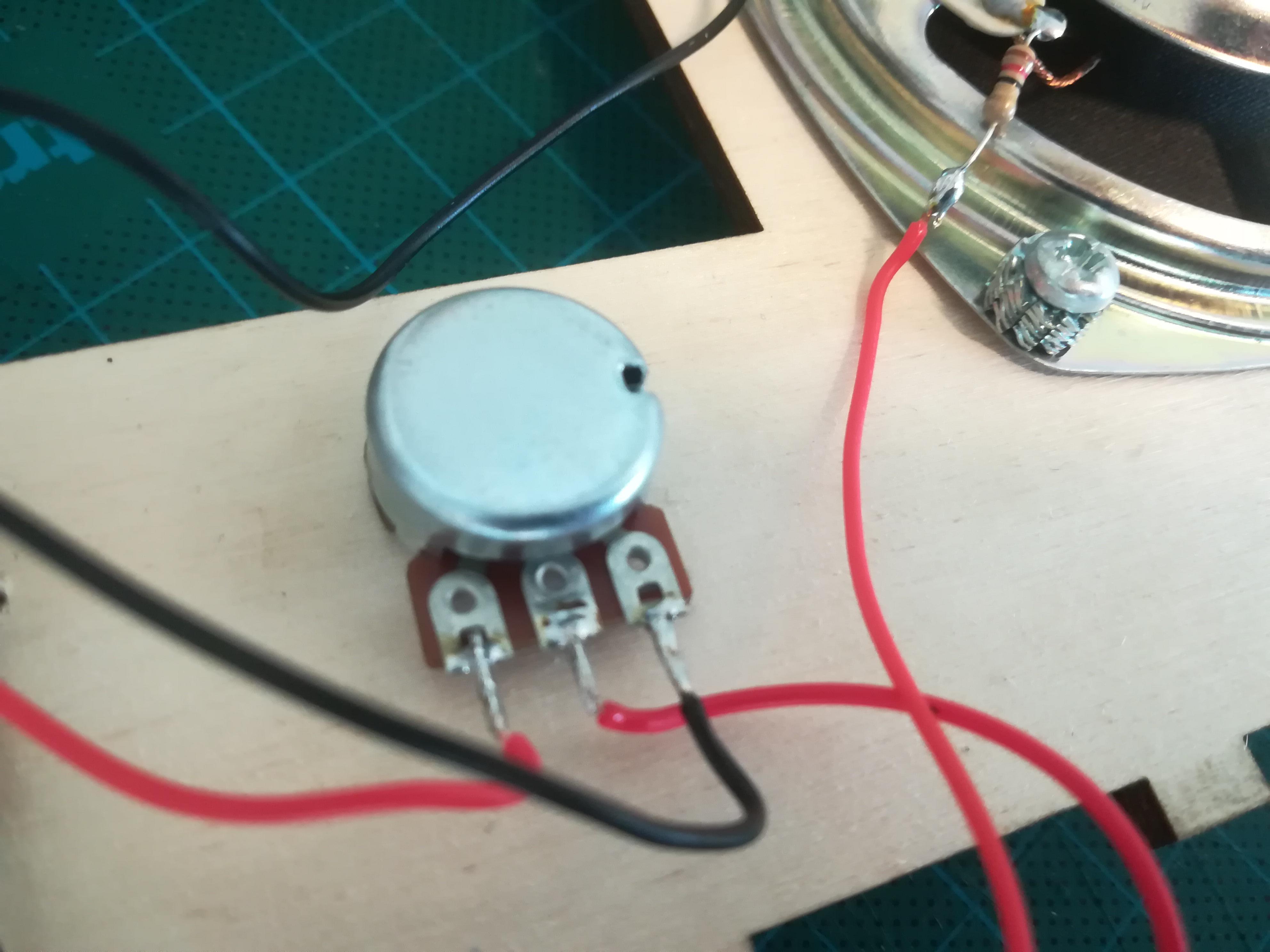
Connect the wires of the sound potentiometer (1K) directly to the speaker and power supply as so (either by soldering or using cable shoes):
- Left leg of potentiometer <---> Power supply (red wire)
- Middle leg of potentiometer <---> Voltage of speaker (red wire)
- Right leg of potentiometer <---> Ground of power supply and speaker (black wires)
Connect Raspberry Pi with power supply through a short USB C cable.
Insert the USB charging port (from step 2) to power supply board.
Connect The EMG sensor board to its jack (from step 2).
Close the radio by putting the back panel on.
How to Use + Other Remarks
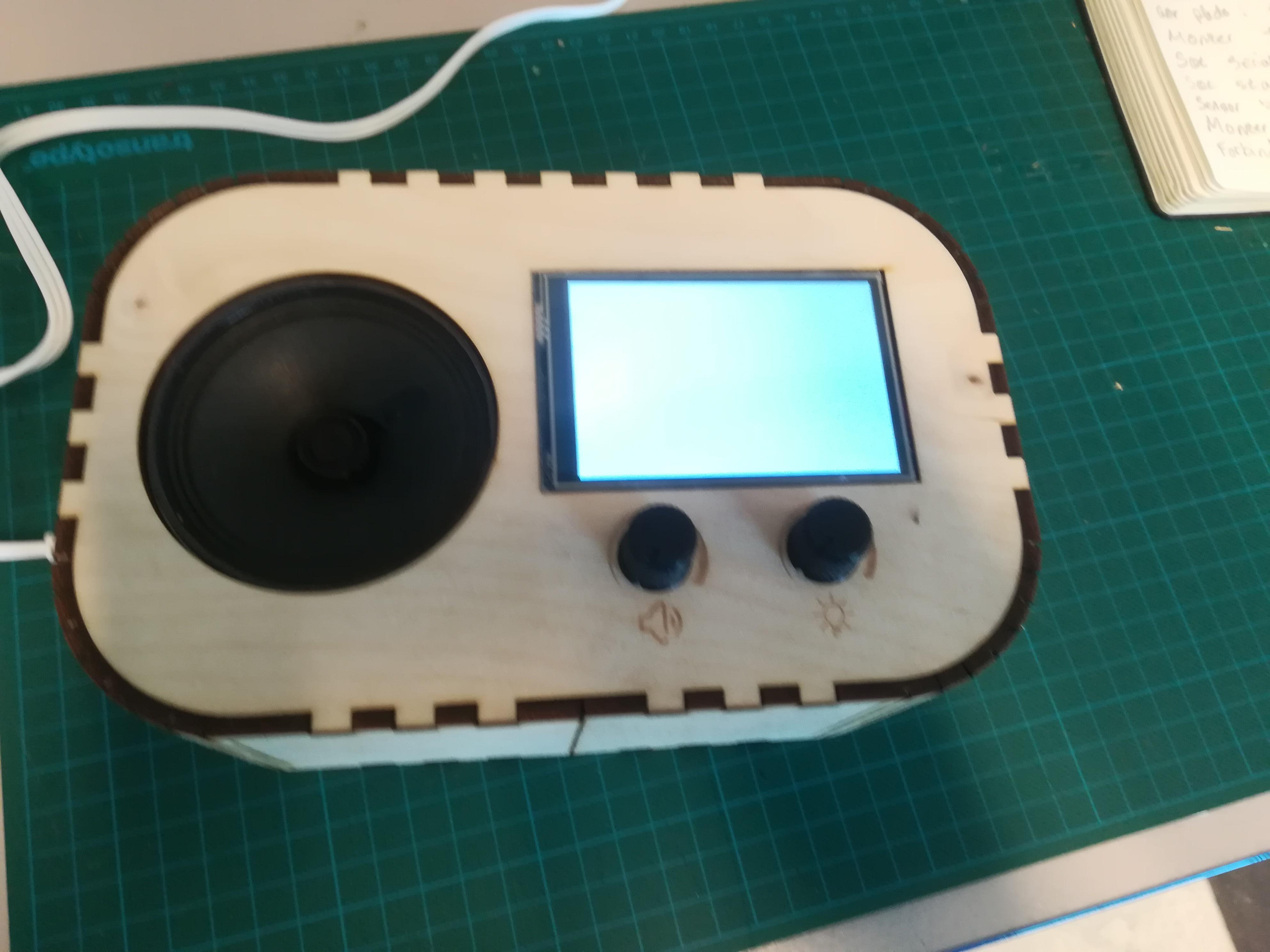
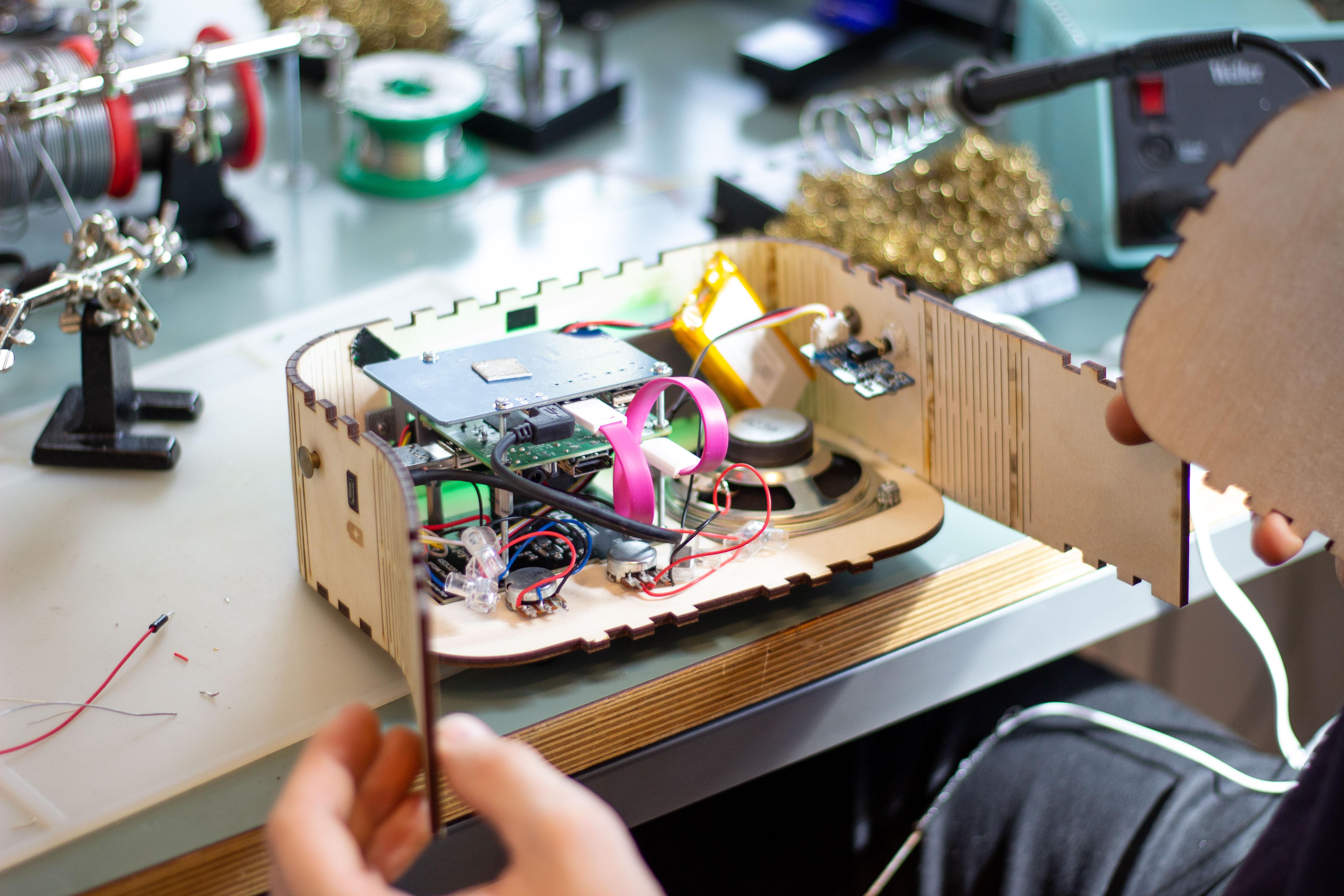
How to use:
- Put the two pads on two different places of the plant (e.g. leaf or stem)
- Stick the metal rod into the soil (GND)
- Make sure the radio has power - either through battery or USB-C cord
- Turn volume and light intensity to desired amount
Good to know:
The radio is not perfectly made, and there's room for a lot of improvement. Here are some notes on what you should be aware of:
- Change the sensor pads if needed (they become less sticky when used many times)
- Battery holds up to ~8 hours
- There is no ON/OFF button
- Volume might not be able to be turnt all the way down, depending on the plant
- Plugging in power supply adds noise to the sensor data
- When plugged to power supply, a warning about “low power supply” appears, this can be ignored
- Taking out the power supply reboots the radio, give it a minute to reboot
- While rebooting, different backend programs open up - do not touch the screen while rebooting