Plant Care System


Hi,
This instructable will show and explain how to build a plant care system, including:
- Plant species recommendation based on 24 hours weather (temperature and light) sensors sampling.
- An automatic plant irrigation system that considers weather conditions (rainy days).
I will show all the components, including electronics, coding, and automation.
Enjoy!
Supplies
- Microcontroller ( I used CPX- circuit playground express with WIFI component)
- Moisture sensor
- Water pump
- 12v battery (for the water pump)
- Relay
Wiring

- Connect the moisture sensor to the microcontroller (pin A1).
- Connect the relay to the microcontroller (pin A2).
- Connect the water pump VCC to the NC pin of the relay and the 12V battery VCC to the C pin of the relay.
- Connect the water pump ground to the battery ground directly.
- Connect the water pump to a hose and pull it to your plant.
Coding Your CPX Sketches

As I introduced, we chose to use Arduino app in order to code and upload the sketches to the CPX.
The next two steps are microcontroller steps, in which I will describe and show an example of my two sketches that perform the following:
- A climate status check.
- Automatic smart irrigation.
Writing the Climate Status Check Sketch

This sketch will take care of the environmental data collection in order to inform the user about the type of plants that can grow up in his specific environmental conditions by measuring the amount of light and temperature of the surrounding.
First, the microcontroller will have to connect to your WiFi network and your MQTT broker (which can be easily launched locally by Eclipse Mosquitto).
Then the microcontroller will push the current light and temperature values to the “light” and “temperature” topics of the MQTT broker every 10 minutes for the next 24 hours - reaching 144 light and temperature pushes in total.
During that state, the microcontroller will show the user a nice carousel loading LED lightings.
After 24 hours have passed, the microcontroller will beep and show the user colorful lights on the microcontroller’s LEDs, to sign that the measurements have completed successfully and that a mail with the results is waiting for him on his own mailbox.
The sketch is implemented as a state machine with two states (see figure attached to this step).
Dependencies (libraries):
- Adafruit_CircuitPlayground
- FiniteStateMachine
- TinyGsmClient
- PubSubClient
Code components (attached below):
- Climate_Status_Checker.ino - Arduino sketch
- Connection.h - Helper functions related to the microcontroller connectivity to WiFi and MQTT broker.
- Flasher.h - A class responsible for the carousel loading LED lightings.
Writing the Smart Irrigation Sketch

This sketch will focus on the smart irrigation system, which waters the plant only when the plant’s soil is completely dry.
The microcontroller will check the moisture sensor value in order to determine the soil’s dryness. If the soil is dry, the microcontroller will open a relay that will activate a small water pump for a certain amount of time (1 second in the current example) and will wait 10 more seconds for the water to percolate before checking the moisture sensor value again. The process will repeat until the soil near the plant is moist enough. After the plant has been irrigated, the microcontroller will activate a Blynk webhook that activates an Integromat scenario to send a notification to the user’s phone, telling him that the plant has been watered. Lastly, the microcontroller will be announced once a day at midnight if the upcoming day will be rainy or not (by an Integromat scenario and Blynk virtual pin update). If the upcoming day is rainy, the pump will not be activated on this day.
First, the microcontroller will have to connect to your WiFi network and your Blynk server..
Then the microcontroller will repeatedly check the moisture sensor value (that is placed inside the soil near the plant) until the value is greater than the dryness threshold (1023 is completely dry).
If the soil is dry, the microcontroller will write the relay pin to LOW, in order to activate the water pump for a certain amount of time. Then the microcontroller will wait 10 seconds and go back to the checking (first) state.
If the soil is dry and the pump has been activated, the microcontroller will write to the virtual pin V1 of Blynk, which is connected to a webhook widget on the app. The webhook activates an Integromat webhook scenario that sends a notification to the user’s phone.
Every day at midnight, an Integromat scenario is triggered and changes the value of the virtual pin V0 to a relevant value: 1 if there will be rain today, 0 otherwise. The microcontroller will update its state according to the rain chance for today, and will ignore the moisture value if there is an expected rain today.
The sketch is implemented as a state machine with four states (see figure attached to this step).
Dependencies (libraries):
- Adafruit_CircuitPlayground
- FiniteStateMachine
- BlynkSimpleShieldEsp8266
- ESP8266_Lib
- TinyGsmClient
Code components:
- Smart_Irrigation.ino - Arduino sketch
- Flasher.h - A class responsible for the carousel loading LEDs lighting (same as the one in the previous step).
- Connection.h - Helper functions related to the microcontroller connectivity to WiFi (very similar to the one in the previous step, omitting the MQTT logic).
Building a Simple Blynk App on Your Smartphone


Blynk is an application that lets you connect your CPX to your mobile. It contains widgets (kind of features) that allow you to perform actions and transform data to and from your CPX.
- Download Blynk app and login (possible via your Facebook account).
- Create a project and go to its settings (clicking on the hexagon symbol).
- Add your CPX as a device (Use “Arduino MKR1000 WIFI”).
- Copy the “AUTH TOKEN”, you need it both for the HTTP request module in integromat and for your Arduino code.
- In your project, create a “WEBHOOK” widget, fill its OUTPUT field with V1 (a virtual pin that will be used later in your arduino code to read from), it’s URL field with the URL of the Webhooks trigger of the integromat “Smartphone notification” that we made earlier. Choose “GET” as a method.
Creating Integromat Scenarios

Integromat is a web platform that allows you to create automation scenarios that connect a variety of web applications, using their APIs in a graphical comfortable way.
The next three steps will show you how to create the scenarios needed to preform those actions:
- Get a daily weather forecast and tell Blynk if a rainy day is expected.
- Send a Gmail message by request.
- Send a push notification to your smartphone every time there occurs successful irrigation.
Integromat Scenario- Weather Forecast to Blynk

Get a daily weather forecast and tell Blynk if a rainy day is expected. The answer will be used in order to prevent the CPX from irrigating when there is natural irrigation by the rain.
- Use the weather API “Get daily weather forecast” (of tomorrow) module as the scenario’s trigger.
- Extract the value of the key named “Status”. This value will equal “Rain” in case it is a rainy day. If you want to be more precise, combine it with the value of the key named “Rain”, which will contain a numerical value of rain precipitation (by millimeters). In my implementation, it is stored in the TOOLS “Set variable” module as a parameter, but it is not mandatory.
- Finally, use the HTTP “Make a request” module to make a GET request to Blynk with the “isRainy” value (1/0) as a Query String parameter. For the URL address, use this form: “http://<blynk-cloud.com IP>/<Authentication token>/update/v0”, where the IP can be found by pinging “blynk-cloud.com” in your cmd, the token is brought from Blynk app (described in step 5), and “v0” represents the virtual pin that you will read from in your arduino code.
Integromat Scenario- Sending a Gmail Message by Request


Send a Gmail message by request. This scenario will receive a request with details from the Node-Red server (detailed in further steps) when the CPX’s light and temperature sampling is done and will send the user the matching plant details via Gmail.
- Use WEBHOOKS “Custom webhook” module as the scenario’s trigger. Copy the hook URL address to use it later on your server. We expect to get a JSON string as the request’s body. I will show a template example of how it can be designed, but it can be performed otherwise as long you match it to your needs (you can send a request one and receive it in integromat in order to see its structure).
- Use Gmail “Send an email” module in order to send the email message containing all the plant details. For this module use, you will need to create a “connection” to your Google account. Click the “online help” link in order to complete this procedure- there are some useful explanations and video guides there. For the message’s content, use HTML “img” tags to implant pictures by their URLs.
Integromat Scenario- Sending Push Notification to Your Smartphone

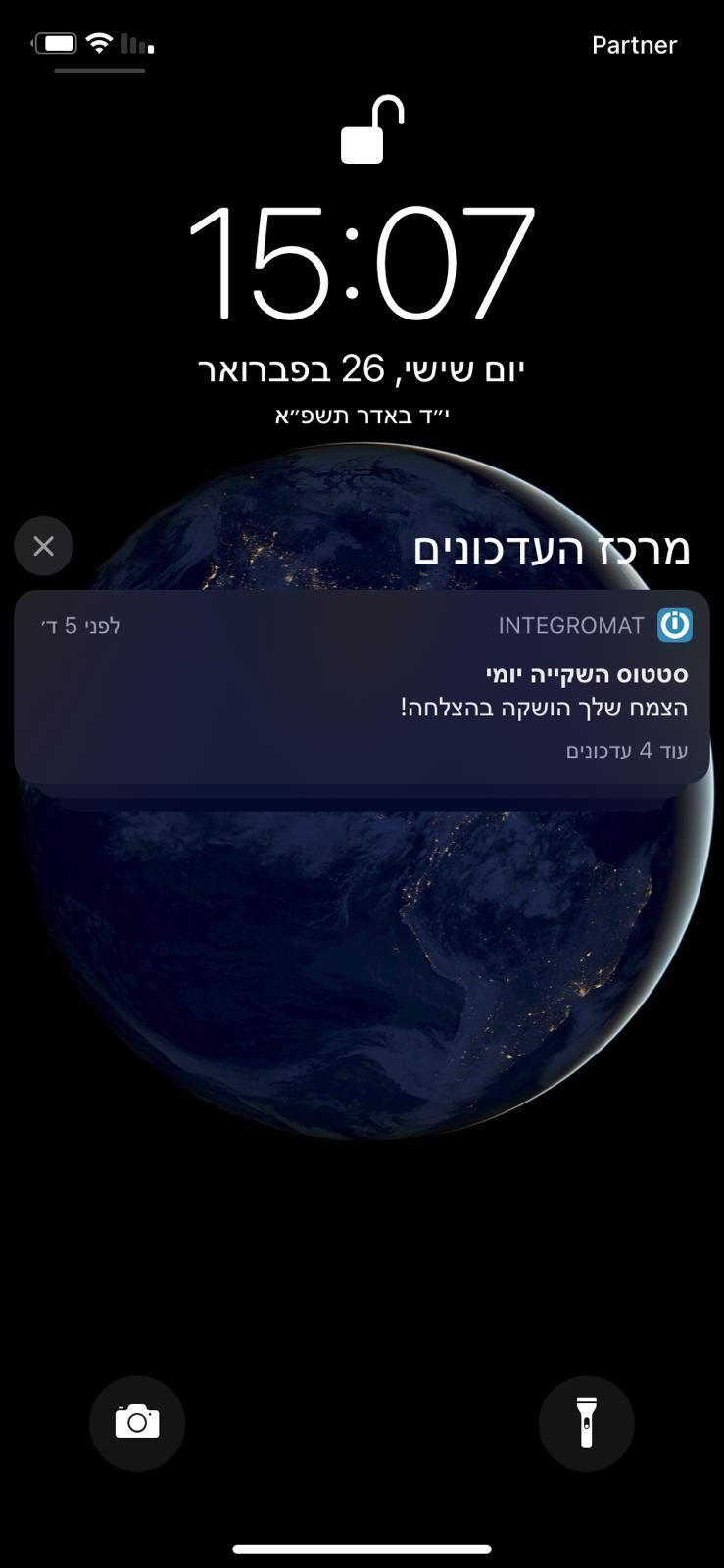
Send a push notification to your smartphone every time there occurs successful irrigation. Here I will Use Apple IOS notification, but you can do the same with Android instead.
- Use WEBHOOKS “Custom webhook” module as the scenario’s trigger. Copy the hook URL address to use it later (this time on your Blynk app). This hook will receive a GET request with no parameters or body content at all because I chose only to notify about irrigation success. But, of course, you can add multiple states using Query String parameters.
- Use Apple iOS “Send a push notification” module. This will require you to download the “integromat” application on your smartphone. After that, you just need to select your device in the Dropdown menu in the “Device” field. The other fields are simple and intuitive.
Setting Up Your Node Red Server

We use Node-Red to perform all of the backend procedures of our project.
The next 5 steps will explain and demonstrate how the logic works. In addition, I will provide the complete flow for your own usage.
Building a Node Red Server and Fetching Data

- Create a Node-Red server and start a new flow.
- Initialize Flow Variables - start a new base path for the future data file.
- Start Fetching Logic- start fetching data to the file after the first message with the “START” payload and collecting samples of data from both MQTT brokers, including messages with the light and messages with the temperature values.
Manipulating the Data
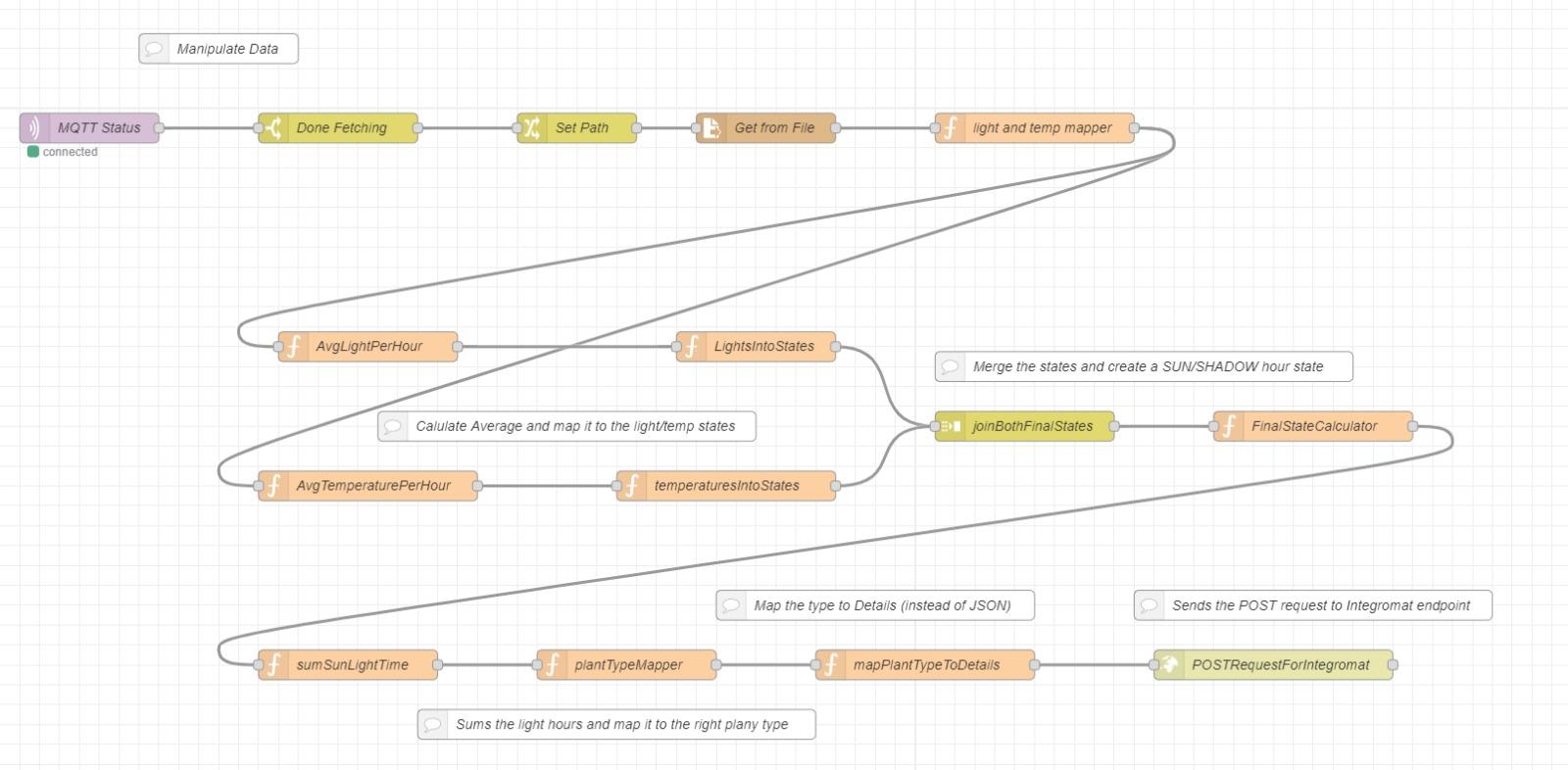
- After collecting the data to the CSV file (at the end of 24 hours), a “DONE” payload is being sent from the MQTT broker. We want to calculate the number of sunlight hours in the spot over the last 24 hours.
- Fetching the Temperatures and Lights data from the CSV file (6 samples per hour X 24 hours = 144 samples of data).
- Temperatures and Lights data are being calculated separately. We are calculating each hour’s average value (The average light & the average temperature, per hour).
- Mapping the values into dedicated light and temperature states as the following:
- The light states (Light value, State):
- 0-299 : Shadow (state 0)
- 300-999 : Indirect Light (state 1)
- 1000-1024 : Direct Light (state 2)
- The temperature states (Temperature value, State):
Under 16 degrees: Cold (state 0)
16- 26 : Comfort (state 1)
Above 26 degrees : Warm (state 2)
- The light states (Light value, State):
Calculating Sunlight Hours

- Now that we have the temperature and light data mapped into their states, we can easily calculate the number of sunlight hours
- Let’s begin mapping all 24 hours while deciding the state of the particular hour - (whether it was a SUN or a SHADOW hour), following the logic above (which also handles edge cases where the state wasn’t clear enough):
- If the light value was Direct Light(2) =clearly a Sun hour
- If the light value was Shadow(0) =clearly a Shadow hour
- If the light was Indirect Light(1) we decided to classify the temperature :
- If the temperature was Cold (0) = A Shadow hour
- If the temperature was Comfort/Warm (1/2) = Sun hour
- Summing up the sunlight hours in the particular day.
Mapping Sunlight Hours to Plant Types

- Mapping logic (Sunlight hours, Plant Type):
- 0 hours: Shadow lover plants (state 0)
- 1-2 hours: Indirect sun lover plants (state 1)
- 3-5 hours: Partial sun lover plants (state 2)
- 6+ hours: Direct sun lover plants (state 3)
Sending POST Request to the Integromat Scenario

Fetching the plant's type details from the JSON file and sending them to the Integromat scenario with an HTTP POST request in order to use it to send an email message (detailed in step 8).
A template of the JSON file is attached below: