Pimp My Wreck

Introduction
Hello all!
We are two computer science students from IDC, and as students, we settle for mediocre vehicles (at least until we get a job). By then, we have the passion to upgrade our wrecks to at least feel cool with what we have.
Fortunately, we take an IoT course led by Zvika Markfeld from the ForRealTeam, and we gained the necessary tools in order to "pimp our wreck".
We will guide you through the construction of our "pimping kit" if you too have a wreck and wish to pimp it.
You are more than welcome to change, adjust and add new elements and features of your desire (and share of course).
This project is dedicated to all "Pimp My Ride" viewers and Zvika our awesome instructor! Thank you!
Our Kit
We constructed our kit for the needs we needed for our wreck:
- Speed dial via an infra-red remote control attached to the steering wheel. This allows the driver to focus on the road and not to deal with their phone while driving.
- Parking Location via a reed switch attached to the gear. When you shift to parking, you will receive an email with the coordinates of where your car is.
- Note-to-self, also via the reed switch. You can write yourself a note when you enter the car, and you'll get it by email as soon as you park so you don't forget whatever it is that you may need.
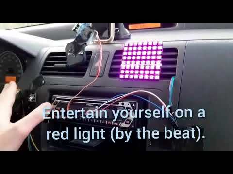
- Glamorous Interior Lighting via a led matrix. This comes to assist us when the interior lighting is broke or to upgrade it. You open the lights of the matrix via the infra-red remote controller and change its colors by a piezo sensor. The piezo sensor receives its signal through vibrations. This lets you drum on your dashboard and enjoy a dazzling light show - like a Rainbow in the Dark!
- Adafruit IO Dashboard displaying an indication of whether the car is currently parked and its last parking location on a map.
Supplies
- 1 x ESP8266 Board (We used Wemos D1 mini)
- 1 x Micro-USB Cable
- 1 x IR Remote
- 1 x IR Reciever
- 2 x Led Bulbs (of different colors, if possible)
- 1 x Reed Switch
- 1 x Piezo Sensor
- 1 x Adafruit NeoPixel (8x8)
- 1 x Micro Servo (We used SG90)
- 1 x Stylus pen, or any other such object that's touch-responsive with your smartphone
- 10 x Jumper Cables (that is the very minimum amount, you'll most likely need more - as well as extension cords. The exact amount depends on the size of your car and the way you want to set up the kit inside it)
- 1 x Hopeless Wreck of a Car
The General Flow
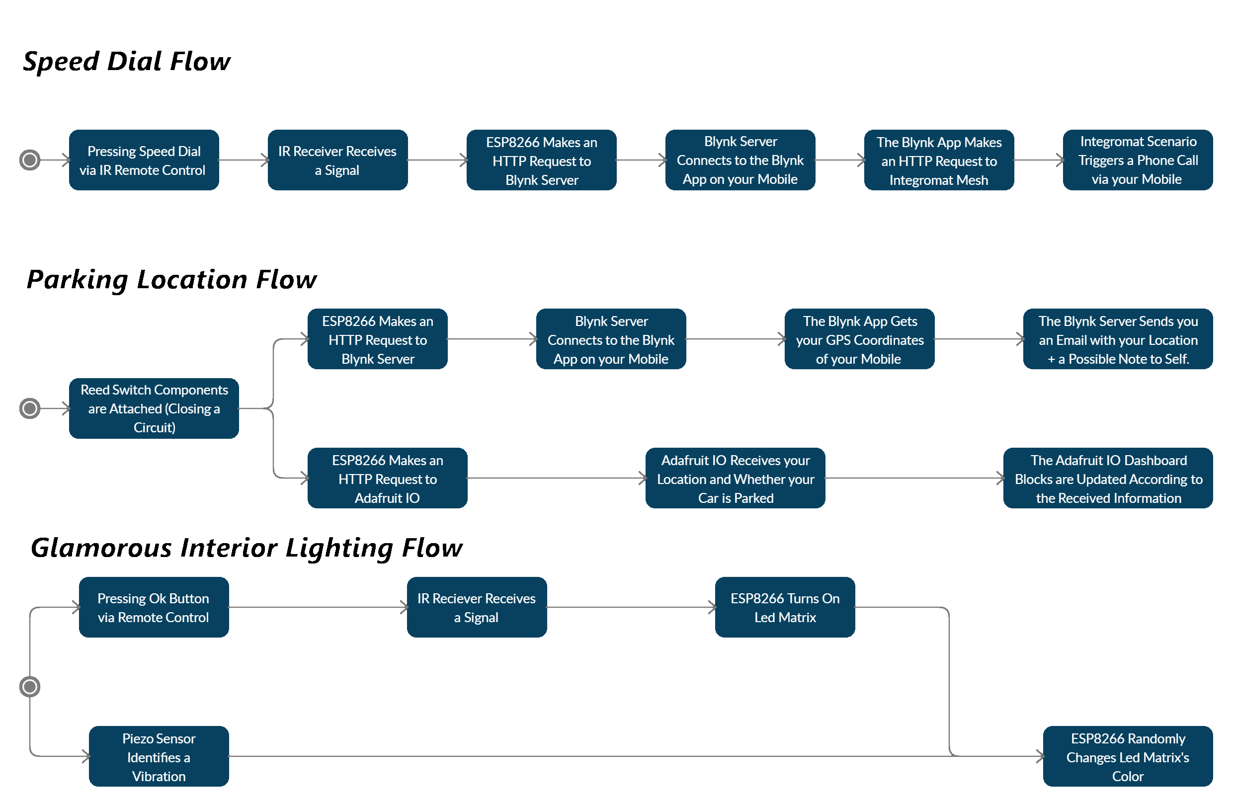
The kit is designed to reside in your car. The ESP8266 is connected to the car charger to get power (you can also use a power-bank if you want).
It is also connected to your mobile device's Hot-Spot to get an internet connection via WiFi.
Our kit is designed for Android users - iPhone users can use it as well, however speed dial would not be possible with an iPhone.
Setting the Environment

Setting the Integromat Scenarios for Speed Dial
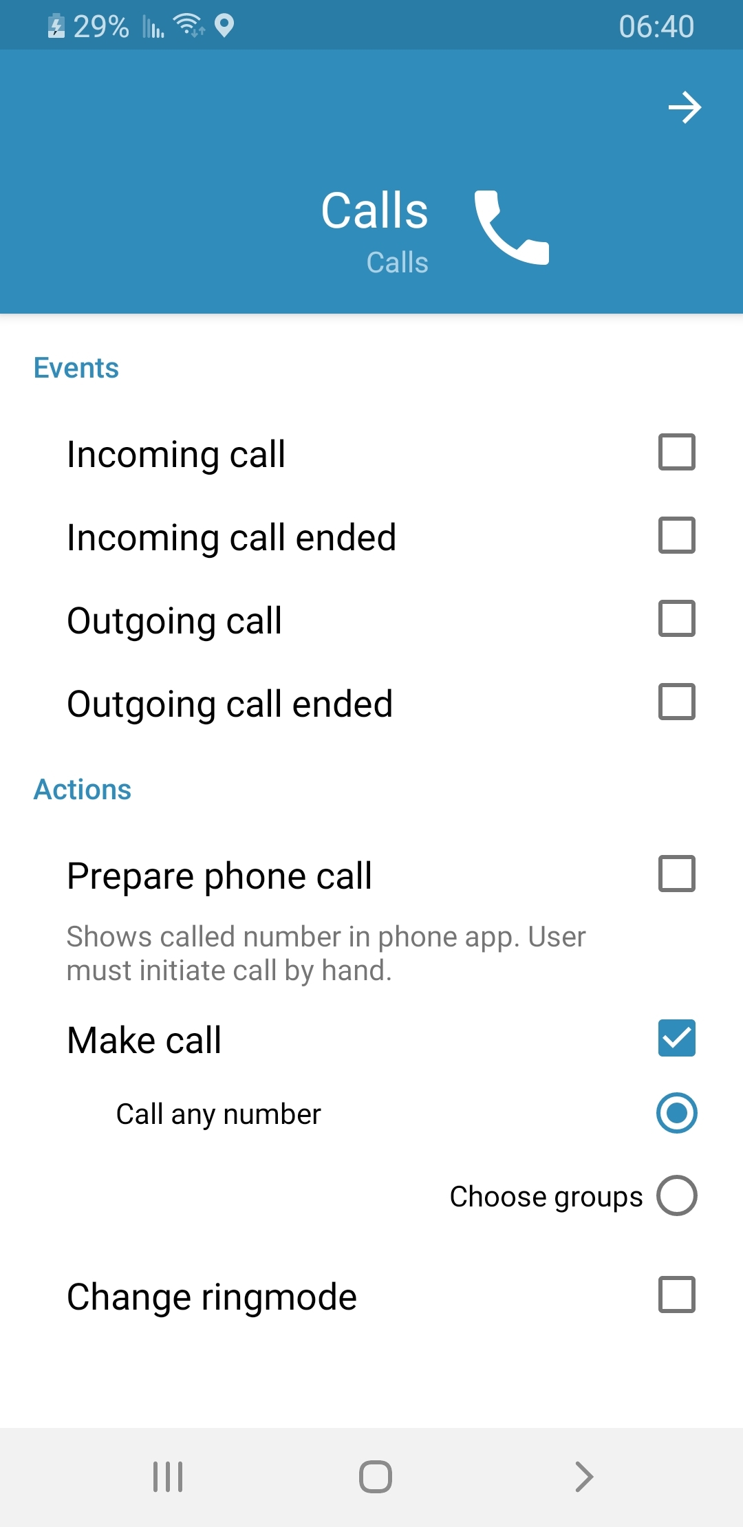
First of all, in your Integromat app, go to Settings → Calls and allow the actions:
- Prepare Phone Call
- Make Call (call any number), as seen in the image.
Next, go to the Integromat website and follow these easy steps:
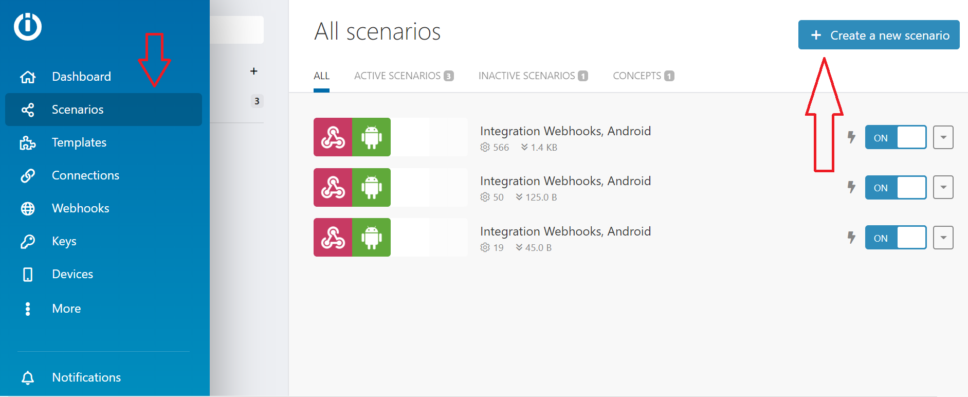
- Go to "Scenarios" on the left-hand menu, and click the "Create new scenario" at the top right of the screen (see image).
- Choose the "Webhooks" and the "Android" services, and click "Continue".
- You'll be transferred to the creation screen. Click on the empty module and choose the Webhooks service.
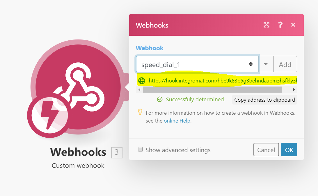
- Choose the "Custom Webhook" trigger and click "Add". Give your Webhook an indicative name, such as, say, "speed_dial_1" (IP restrictions aren't needed).
- Click "Save", and a URL will appear in blue right under the name of your new Webhook (see image). Copy and paste it somewhere you'll remember and click "OK".
- Click "Add Another Module" (the small semicircle on the right side of your Webhooks module).
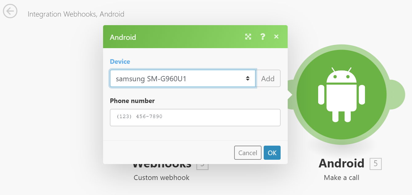
- Choose the Android service and the "Make a call" action.
- In the "Device" field, add in your device (should appear in the drop-down menu, provided you've successfully downloaded the mobile Integromat app to your device and signed into your account), and insert a phone number of your choosing in the "Phone Number" field. Finally, click "OK".
- Repeat steps 1-8 once more. Remember to give your new Webhook a different name (such as "speed_dial_2"), and insert some different phone number (unless you want to call the same person with 2 different buttons... We all have someone we love that much!)
The Blynk Dashboard
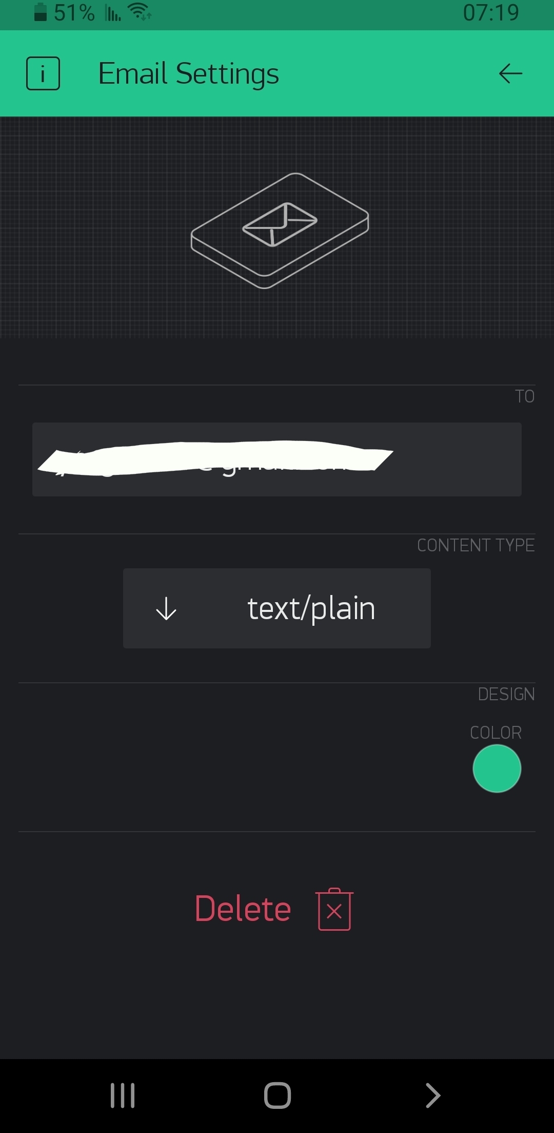
Go to the Blynk app.
Create a new project.
An authentication key will be sent to your email address - keep that key, it's important!
Now, follow these easy steps:
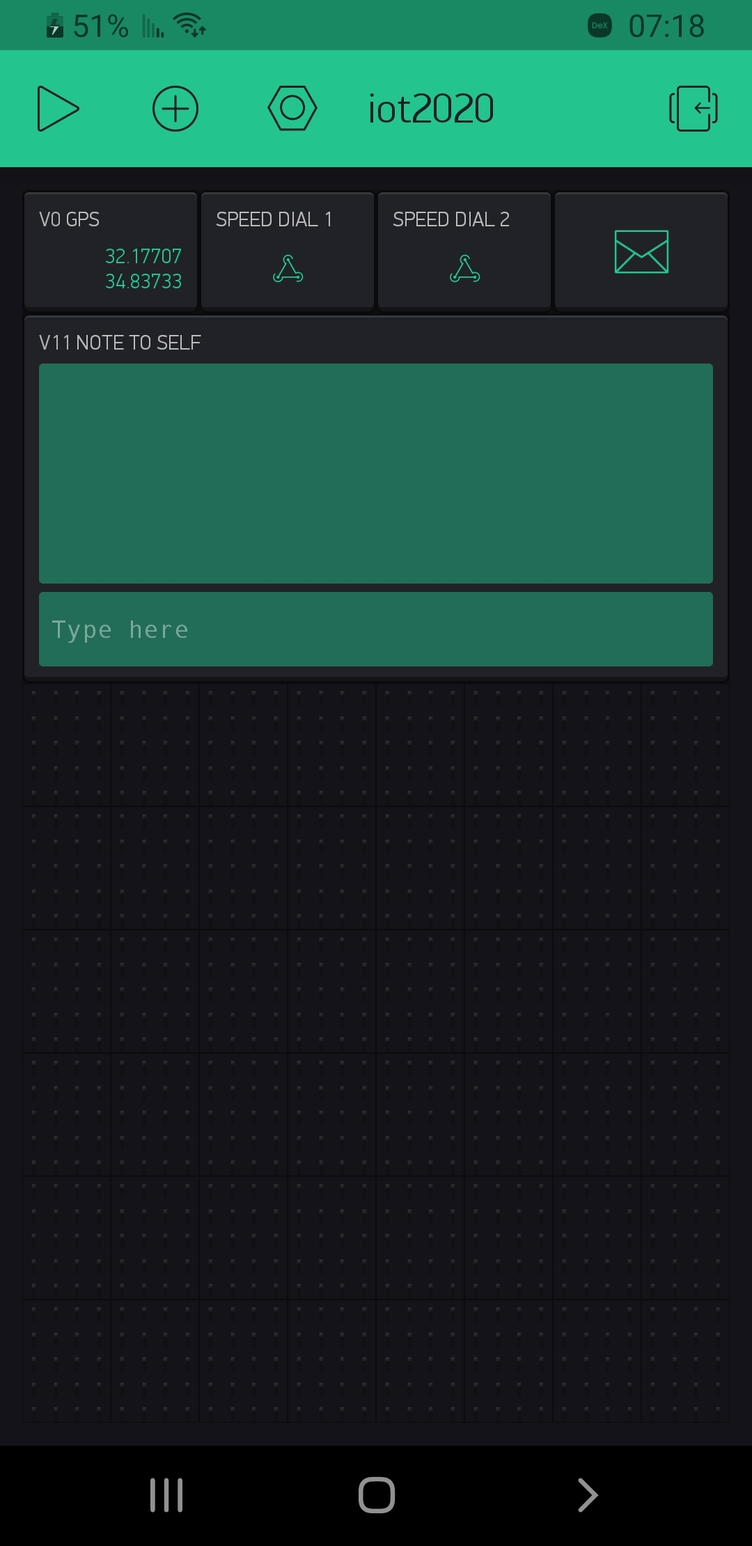
- Click the small (+) button, and add the following widgets to your dashboard:
- 2 x Webhooks.
- 1 x Email widget.
- 1 x GPS Stream.
- 1 x Terminal.
- Set the following:
- The GPS Stream to virtual pin V0.
- The Webhooks to virtual pins V1 and V2 respectively.
- The Email widget to virtual pin V10.
- The Terminal to virtual pin V11.
- Now:
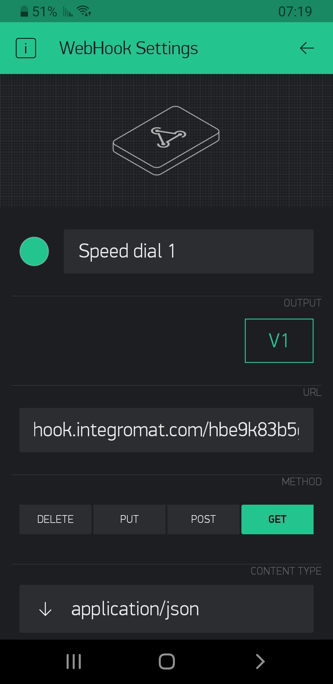
- Tap each Webhook widget, and in the URL field, insert the Webhook URLs that you got from Integromat (see image).
- Make sure that the email address in the Email widget is your correct email address (it is set by default to the address you used to sign up to Blynk), and change the "Content Type" field to "text/plain".
Notes:
- You start with 2,000 energy units and each Blynk widget costs a certain amount of energy. You can purchase more energy and add additional Webhook widgets to allow additional speed-dials!
- We skipped V3-V9 in step 2 in case you want to add more Webhooks.
- Other adjustments to your dashboard, such as tweaking the color of your Terminal (like we did, as you can see in the picture) are up to you!
- For additional info on Blynk, its diverse selection of widgets and some very comprehensive documentation and usage examples, check out this link.
Adafruit IO Dashboard

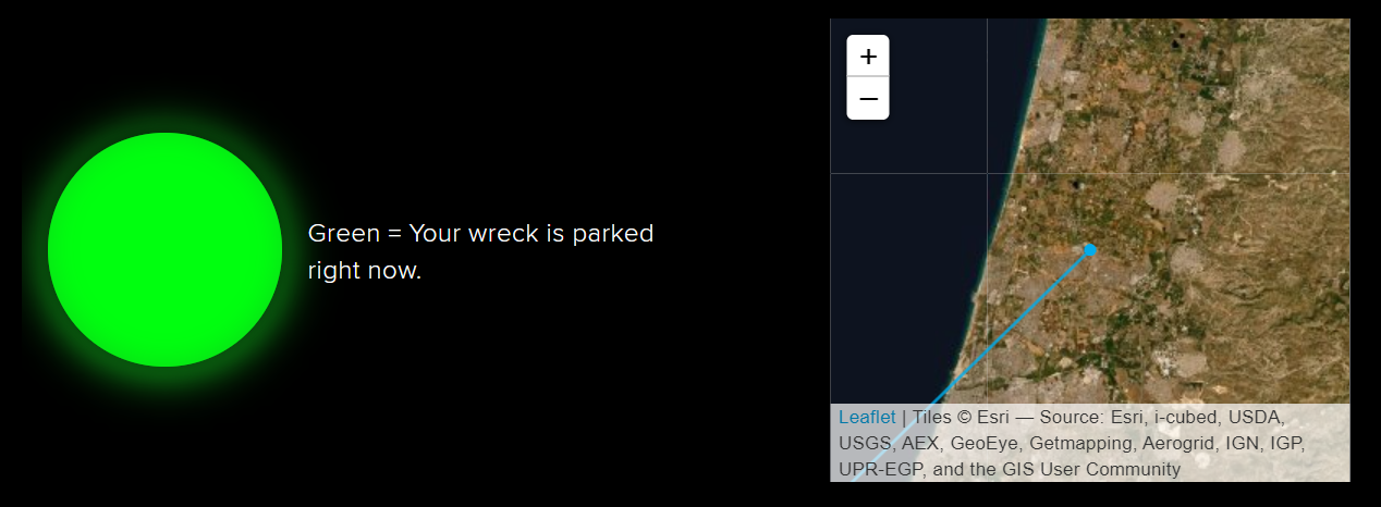
In the Adafruit IO dashboard, we can see 2 important details:
- Whether the car is parked or not
- Most recent parking location
This is how we set it up:
- In the Adafruit IO website, go to "Feeds" tab and create 2 new feeds: "location" and "parked".
- Go to the "Dashboards" tab, open the "Actions" drop-down menu and create a new dashboard. Name it however you want, and add a description if you want. Click "Create", and press the new link that's bee created.
- In the dashboard you've just created, you will see 7 small square buttons (see image). Press the yellow key button, and a pop-up window will open. Copy the string you see in the "Active Key" field and paste it somewhere you'll remember.
- Now click the blue "+" button, and add an "Indicator" block. Choose the "parked" feed and continue to the next step. Type in some indicative title, change the on and off colors if you want, and in the "Conditions" drop-down menu choose "=", and set the value below it to "1". Finally, click "Create Block".
- Click the blue "+" button again, and add a "Map" block. Choose the "location" feed and continue to the next step. Type in some indicative title, choose however many hours of history you want, and whichever type of map you want (in the image above we used "Satellite Imagery", but all types work just the same). Finally, click "Create Block".
- Click the green gear button. Resize and re-position the Indicator and Map blocks any way you like, and click "Save" (the "Save" button will appear right by the original 7 buttons).
You can leave your Adafruit IO details with someone you trust, or even create the dashboard through a friend's account, and they'll be able to use the dashboard and see when your car is parked and where.
Hardware (the Fun Part!)

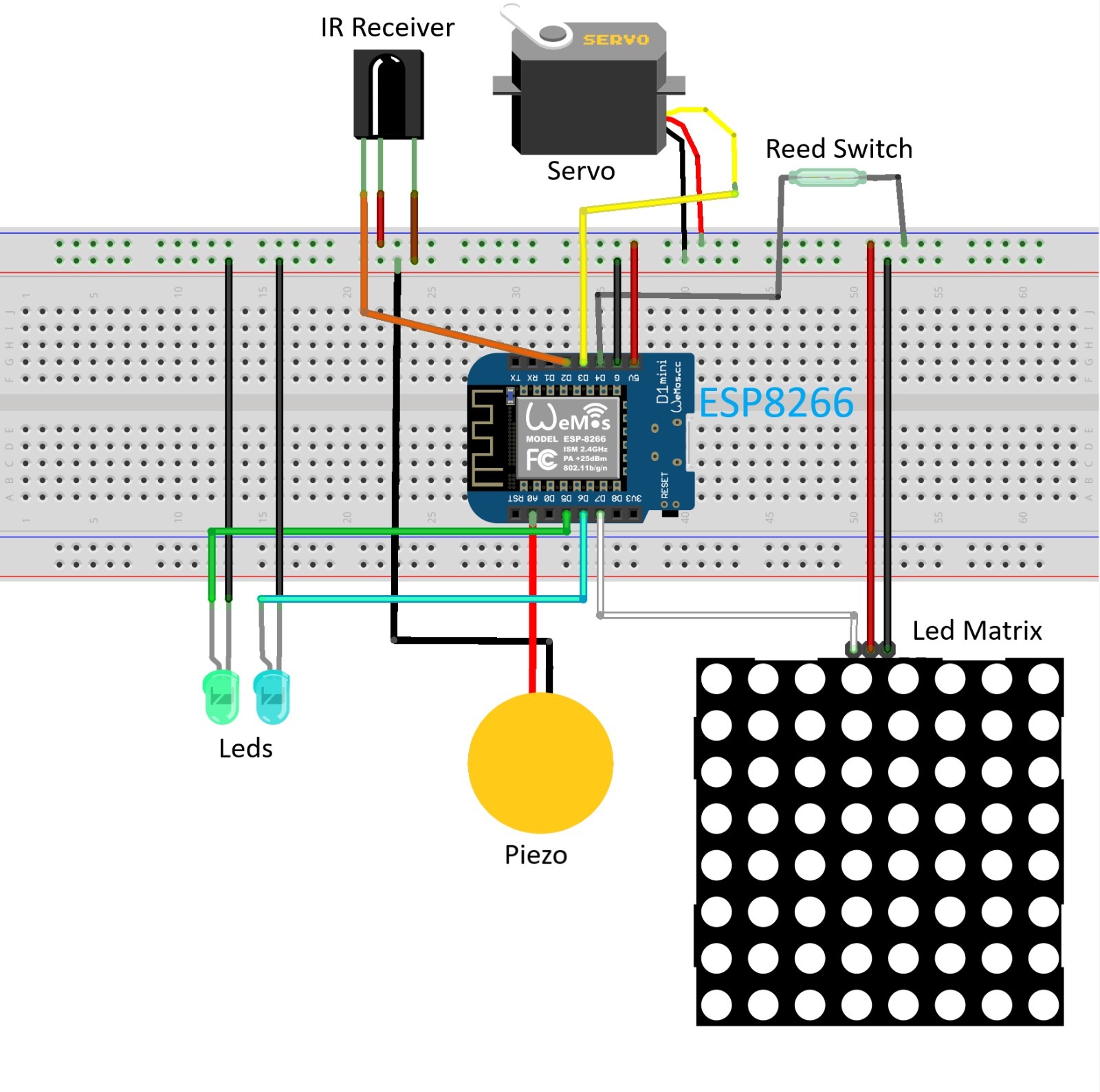
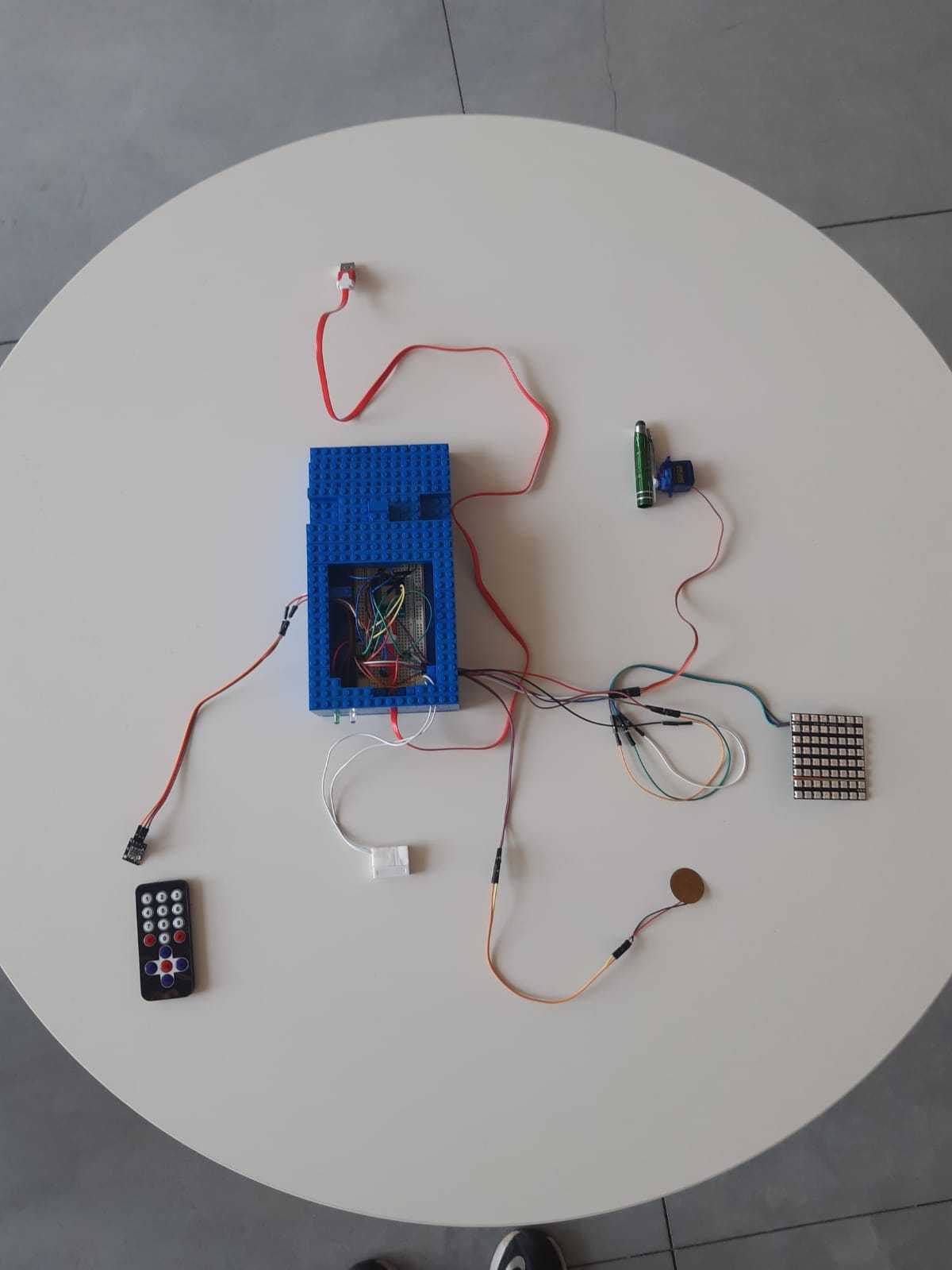
We will connect the hardware in the following manner:
- Infra-Red Receiver:
- Connect VCC to (+) on the breadboard.
- Connect GND to (-) on the breadboard.
- Connect the signal pin to D2 on your ESP8266 board.
- Servo motor:
- Connect VCC (red wire of the Servo) to (+) on the breadboard.
- Connect GND (brown wire of the Servo) to (-) on the breadboard.
- Connect the signal pin (orange wire of the Servo) to D3 on your ESP8266 board.
- Reed switch:
- Connect one of the pins of the Reed-Switch to (-) on the breadboard.
- Connect the other pin to D4 on your ESP8266 board.
- LED bulbs:
- Connect the short leg of the 1st LED bulb (we used a green one) to (-) on the breadboard and the long leg to D5 on your ESP8266 board. That LED serves as an indicator that an IR signal has been successfully received by the infra-red sensor.
- Connect the short leg of the 2nd LED bulb (we used a white one) to (-) on the breadboard and the long leg to D6 on your ESP8266 board. That LED serves as a parking light - it will be lit while you're in parking mode (controlled via the reed switch).
- LED matrix:
- Connect VCC (or +5V) to (+) on the breadboard.
- Connect GND to (-) on the breadboard.
- Connect DIN to D7 on your ESP8266 board.
- Piezo sensor:
- Connect one of the pins of the sensor to (-) on the breadboard.
- Connect the other pin to A0 on your ESP8266 board (that is your analog input pin!)
Tips and Recommendations:
- Use as many jumper cables and extension cords as you need. We recommend using quite a lot to allow yourselves as much flexibility as you can when setting up the system in your car.
- Be careful not to get all tangled up in the process though!
- That's quite a bit of hardware, so you can use the images above for reference.
- Finally, we recommend encasing your breadboard and ESP8266 in something that would make it easier to carry to your car, and also protect it in bumpy rides. As you can see, we personally built a LEGO box that held it quite firmly, but many other solutions could work as well!
- Make sure that any case you use has openings for all the necessary cables and wires to go through (there are quite a few of those).
- Also, make sure and that the 2 small LED bulbs are peeking out so you can see them (you should use extension cords for that).
The Code

You can download the full sketch below. We made sure to document it as much as we could, and we think it's pretty easy to understand; however, if you have any issues understanding it, do ask us in the comments below!
Some things to take care of before running the sketch:
- Go to Tools → Board and make sure you're running the right type of board. If you don't see any ESP8266 boards in the drop-down menu, go to the Board Manager and install ESP8266 from there. When you finish installing it, go to Tools → Board once again and choose your type of board.
- Make sure that you put in your WiFi network name and password (you'll be using your smartphone's mobile Hot-Spot), as well as your Blynk authorization token and the Adafruit IO username and key in their appropriate places.
- Run the sketch once, open the serial monitor (Tools → Serial Monitor), and click the "1", "2" and "OK" buttons in your IR remote. Check the numbers you're seeing on the serial monitor and make sure they're identical to the ones defined in the sketch for their respective buttons. If they're different (and they could be), just change them.
- We programmed our Servo Motor to tap the smartphone every 6 seconds. If you feel more comfortable with some other interval, do feel free to make the necessary changes.
- You can also change the force threshold we defined for the Piezo Sensor.
Downloads
Setting the System in Your Car
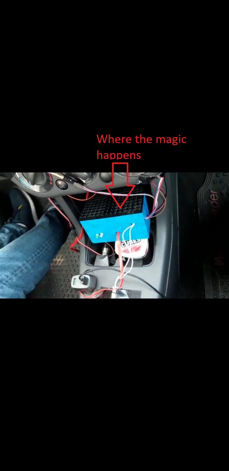
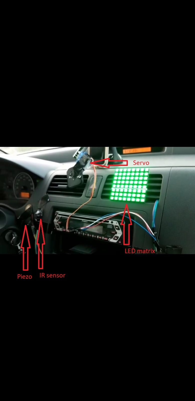
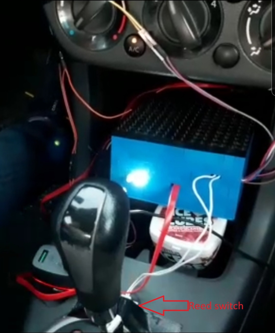
Now that we have everything ready and set, all we need to do is place the system in our car (OMG!!!).
We recommend bringing a bunch of extra jumper cables and extension cords along with you so you can make some adjustments if you want when setting everything up:
- Attach the IR remote to your steering wheel. You can use rubber bands if you want, but we recommend using duct tape to make it sturdier and less prone to fall off. Now, attach the IR receiver somewhere on your dashboard where it could easily receive a signal from your remote.
- Set the LED matrix. Remember, safety first - set it somewhere that isn't directed right at your eyes so it wouldn't blind you when you're driving! We, for example, tied it to the AC vent with a rubber band.
- Attach the independent (wireless) part of the reed switch to your gear stick, and attach the wired part right in front of the gear stick - in such a way that the switch will be closed when you shift to parking.
- Attach the piezo sensor anywhere you like - the location is up to you. You can set it on the dashboard close to your hand so you can drum along to the beat of your music when in red light (like we did), you can set it close to the floor so your matrix changes colors every time you hit a speed bump, or anywhere else you like!
- Set the servo. You have to make sure that you put it carefully somewhere it will be able to tap your smartphone (took us lots of trial and error here), and firmly enough so it won't fall off.
Remember to make sure that no stray jumper cable or extension cord gets tangled up with your gear stick, or anything else that may come in your way while driving!!!
We recommend using rubber bands and duct tape to gather all the cords and cables up in braids and attach them somewhere safe.
Enjoy the Ride!
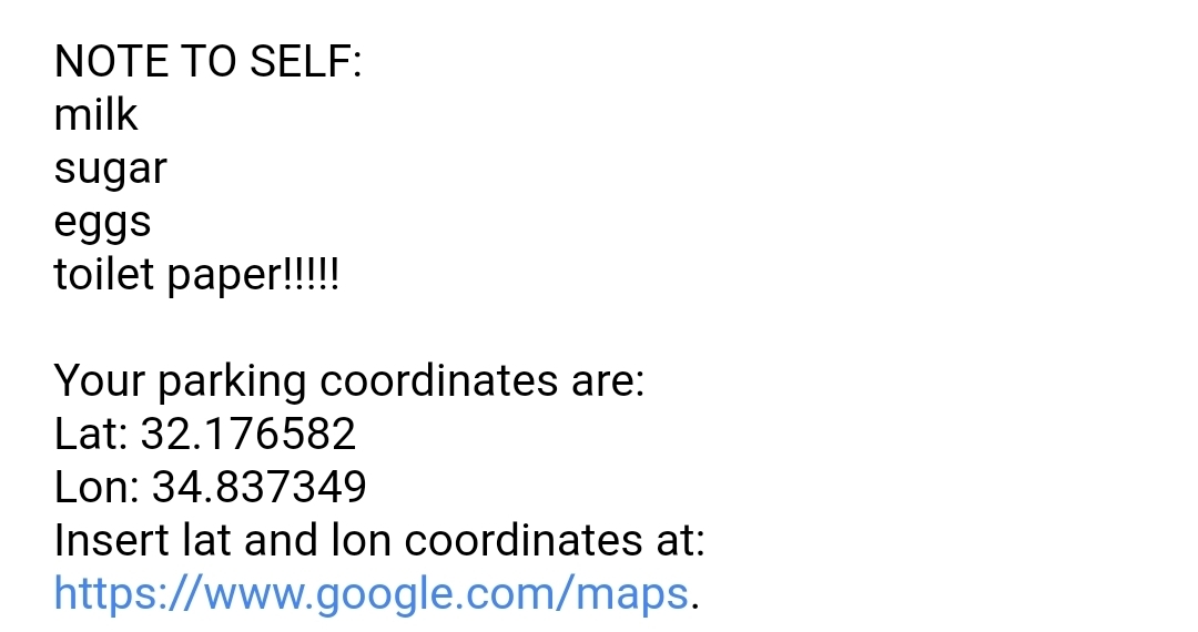
That's it, you're all set!
Take notes of the following things before you drive away:
- Make sure that Blynk is running in the background before you head off. The system won't work otherwise! It's best if you activate Blynk before you start your vehicle. To make sure Blynk is running, hit the small (▶) button at the top-left of your dashboard (as seen in the image from step 4).
- After you started the car, send yourself any reminder that you need via the Blynk terminal: you can use it to send yourself a shopping list for the grocery store, remind yourself to take some package from your trunk, or anything else you don't want to forget. You can send several reminders if you want - they will all be included in the email.
- Make sure that the Integromat app is running in the foreground; speed-dial won't work otherwise. The servo will help you make sure that your smartphone doesn't lock!
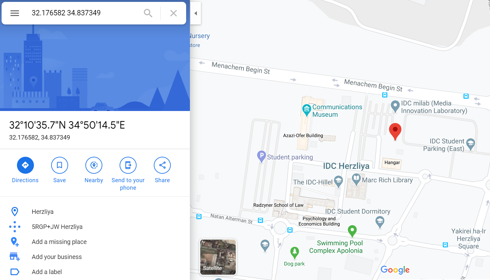
- When you park your car, you'll get the email containing your coordinates, and if you sent yourself a reminder, it will be in the email too! If you don't see it in your inbox, check the spam box and you'll find it. Do take note that your latitude and longitude coordinates have a precision of 6 decimal points - that's really accurate! You can insert these coordinates in Google Maps (link provided in the email), and see right where you parked.
That's all folks! Thank you for reading, we hope that you enjoyed this Instructable and that you'll enjoy building and using your very own "Pimp My Wreck" kit (and please share ✌)!
Drive safe!!!!!