Piezo Instrument Introduction


Hello, this is a tutorial or an instructable I should say on how to turn a Piezo into an instrument on Tinkercad, I had recently found out what the piezo component does on Tinkercad and I had the idea of turning it into a sort of an instrument to play some music with as a piezo can produce certain frequencies.
This was the end result.
Supplies
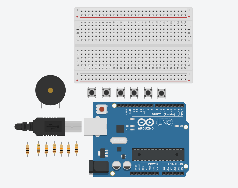
Breadboard Small x 1
Switches x 6
100 Ohm Resistor x 1
10 Kiloohm Resistor x 6
Arduino Uno R3 x 1
Piezo x 1
How to Make the Piezo Instrument

First thing you want to do is the basics,
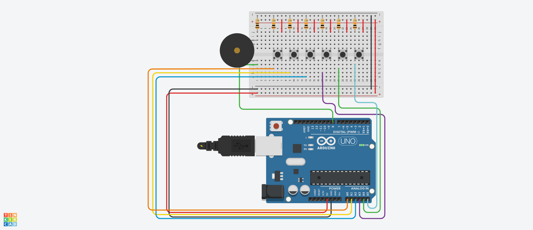
You want all the components laid out on the breadboard as it makes it more organized and easy to connect the wires from the Arduino to the components.
Essentially put all the resistors at the top and connect to GND line on the breadboard as seen in my screenshot. Then take the Power line from the breadboard and connect them straight downwards to the breadboard as in my screenshot.
Connect to the Piezo to the breadboard anywhere you want. This is why it is important to have all the components laid out however you want as that makes it way easier to connect the wires to the components. If you want you can do it how I did it.
If you did not lay out the switches already do that now. Essentially just put them in the gap in the breadboard connecting to both sides of the breadboard.
Now it is time to connect the wires from the Arduino to the components. Connect the 5V on the Arduino to the breadboard Power line and the GND on the Arduino to the breadboard Ground line. That is giving the breadboard and all the components on its power and ground. You also need to connect the opposite voltage and ground lines like power and ground to one another.
Then connect the positive end of the Piezo to number 8 on the Arduino
Connect A0 on the Arduino to the first switch on the far left on it's left pin
Connect A1 on the Arduino to the second switch from the left to it's left pin and basically do that until all switches are connected to a different A# pin.
Almost done!
Code

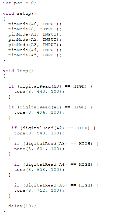
If you laid out the breadboard and connected it to the same pins on the arduino as I did, you can simply just use my code:
int pos = 0;
void setup()
{
pinMode(A0, INPUT);
pinMode(8, OUTPUT);
pinMode(A1, OUTPUT);
pinMode(A2, OUTPUT);
pinMode(A3, OUTPUT);
pinMode(A4, OUTPUT);
pinMode(A5, OUTPUT);
}
void loop()
{
if (digitalRead(A0) == HIGH) {
tone(8, 440, 100);
}
if (digitalRead(A1) == HIGH) {
tone(8, 494, 100);
}
if (digitalRead(A2) == HIGH) {
tone(8, 548, 100);
}
if (digitalRead(A3) == HIGH) {
tone(8, 604, 100);
}
if (digitalRead(A4) == HIGH) {
tone(8, 658, 100);
}
if (digitalRead(A5) == HIGH) {
tone(8, 712, 100);
}
delay(10);
}
That is all there is to it. I hope this was helpful!