Pi-dongle
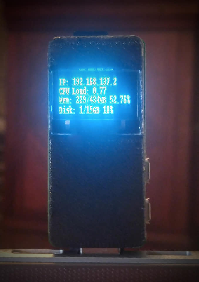
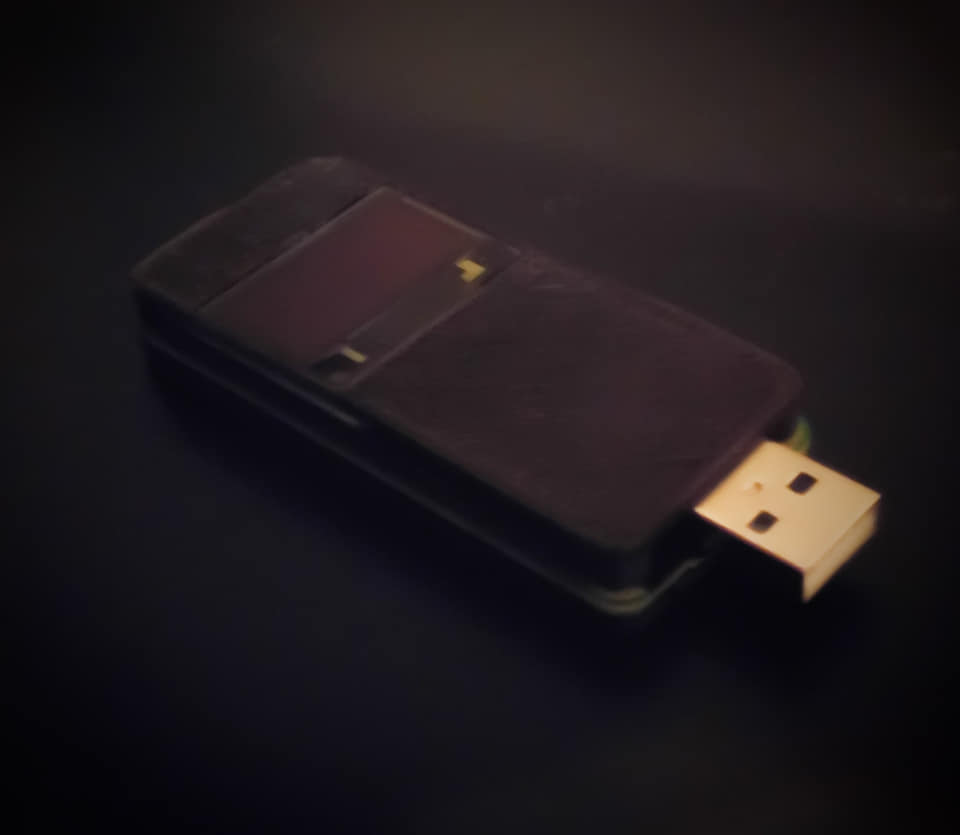
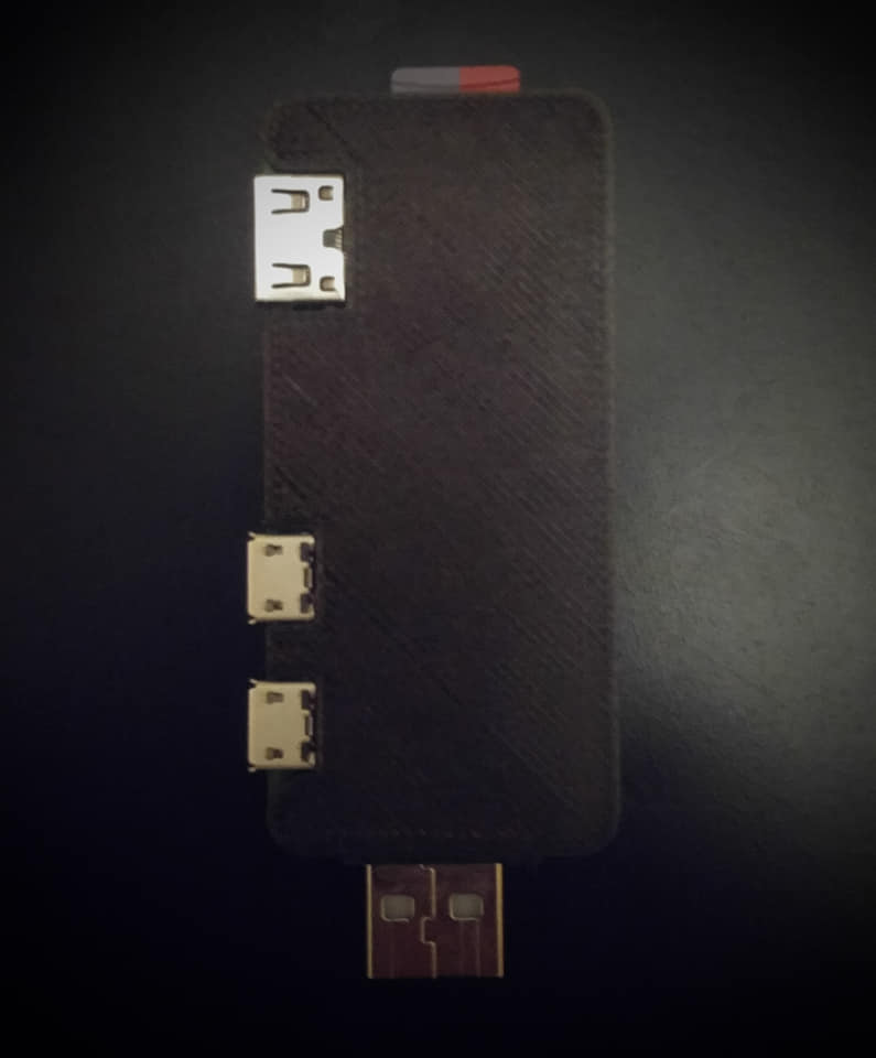
Want a convenient software testing tool, portable local development server, or convenient mini pc on a usb stick? I did, and if you are reading this I suspect you do too. Lets get started!
What you will need
- A Raspberry pi zero https://bit.ly/2pND3DE $5
- Micro SD card https://ebay.to/2Pw8gGD $4
- A 3D printer (or access to an online 3D printing service if you don't own one)
- A cheap 4-wire I2C OLED display https://ebay.to/2pS70m8 $3
- A male USB connector
- Some small insulated wires
- A soldering iron
- Super glue
Most of this you may already have laying around. In my case i salvaged the usb connector and wires from and old broken usb cable.
3D Printed Case
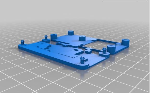
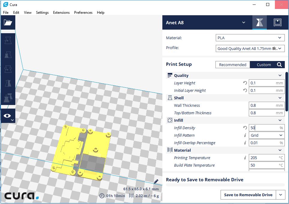
The case is 3D printed. This step is optional but recommended as it protects your pi zero and creates a nice finished looking project. First you will need to head over to thingiverse and download the STL files i designed for the case. There are 2 files available. One includes a window for the OLED display and the other does not in case you want to skip the optional OLED display
https://www.thingiverse.com/thing:2988969
Download the STL file(s) and load them into your slicer of choice. I use Cura because its free and does a good enough job for me. After loading the STL set your slicer to the highest quality settings your printer can support. Export the gcode files and send them to your 3D printer.
Assembly
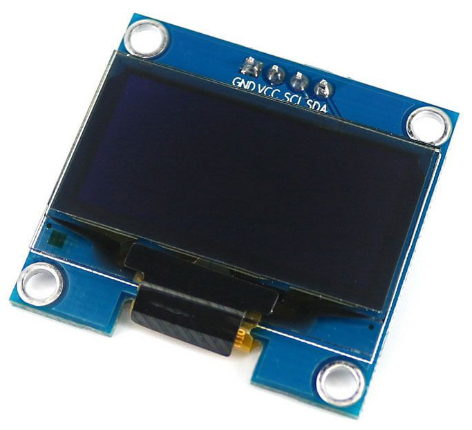
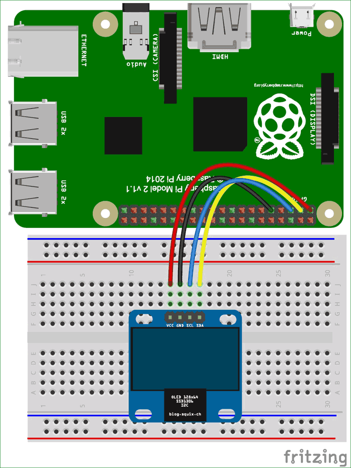
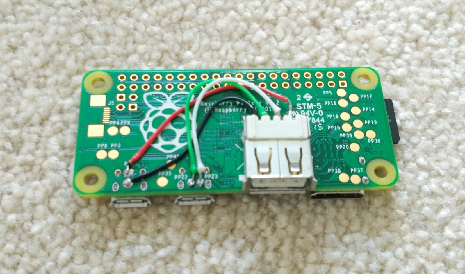
- Connect and solder OLED i2c interface
https://circuitdigest.com/microcontroller-projects... - Connect and solder USB data and power lines
- Put it all together
once the case is printed, you should be able to sandwich everything together. I used a dot of superglue on each corner post to ensure a good solid connection but depending on the quality of your printer you might not need this since the corner posts on the case are designed to clip lock on their own.
Software
- Install raspbian jessie lite on a SD card if you haven't already (lots of other instructables on how to do this)
- Setup ethernet gadget https://bit.ly/2CaTph3
- Setup I2C and OLED display
https://www.recantha.co.uk/blog/?p=18463
https://github.com/adafruit/Adafruit_Python_SSD130... - create a startup script to launch the adafruit oled stats demo:
#!/bin/sh
# oled_launcher.sh
sudo python examples/stats.py - edit /etc/rc.local to launch the script at startup
(cd /path/to/your/script/; sh oled_launcher.sh) &
Done!
At this point you should have a fully working PI-Dongle
Now if you want you can add a webserver or database or any other software packages you would like. I'm using mine as a development platform for testing c#/mono projects on the raspberry PI. Recently i have installed a redis instance using this guide:
https://habilisbest.com/install-redis-on-your-rasp...