Physical Twin: an Interactive Remote Painting Device
by ekinsila in Circuits > Arduino
1525 Views, 2 Favorites, 0 Comments
Physical Twin: an Interactive Remote Painting Device
by Ekin Sila Sahin, Lior Skoury, Simon Treml
The project was conducted as a part of the Computational Design and Digital Fabrication Seminar in the International Master of Science Programme: ITECH
Introduction
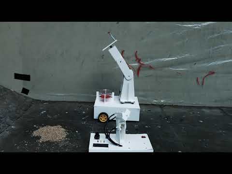
Physical Twin is an artistic robot which enjoys painting with the collaboration of humans. Integrating the experimentality of the field of robotics with the human imagination, the robot can be remotely and physically controlled while inherently avoiding obstacles, besides can learn from those transferred directions.
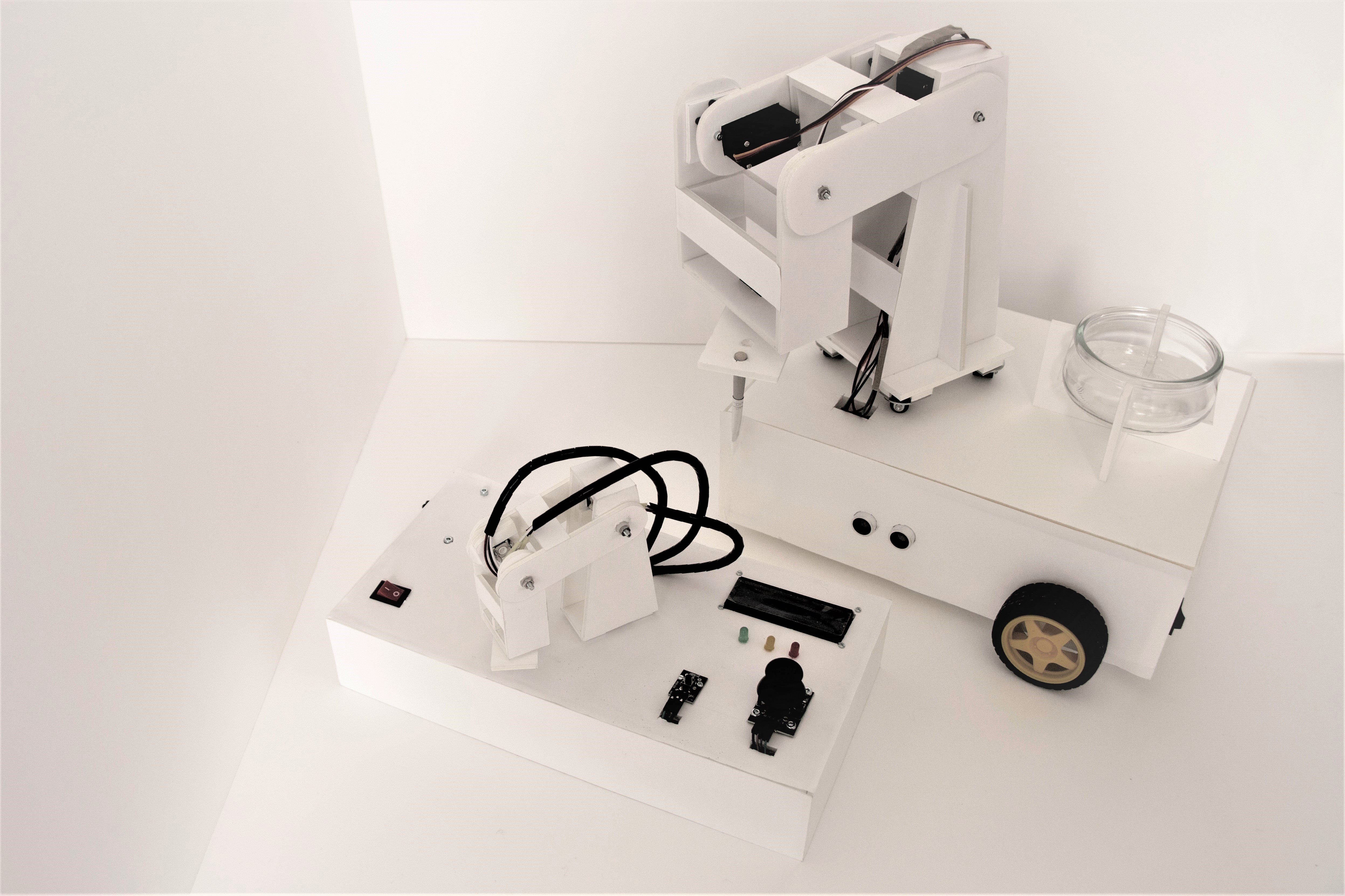
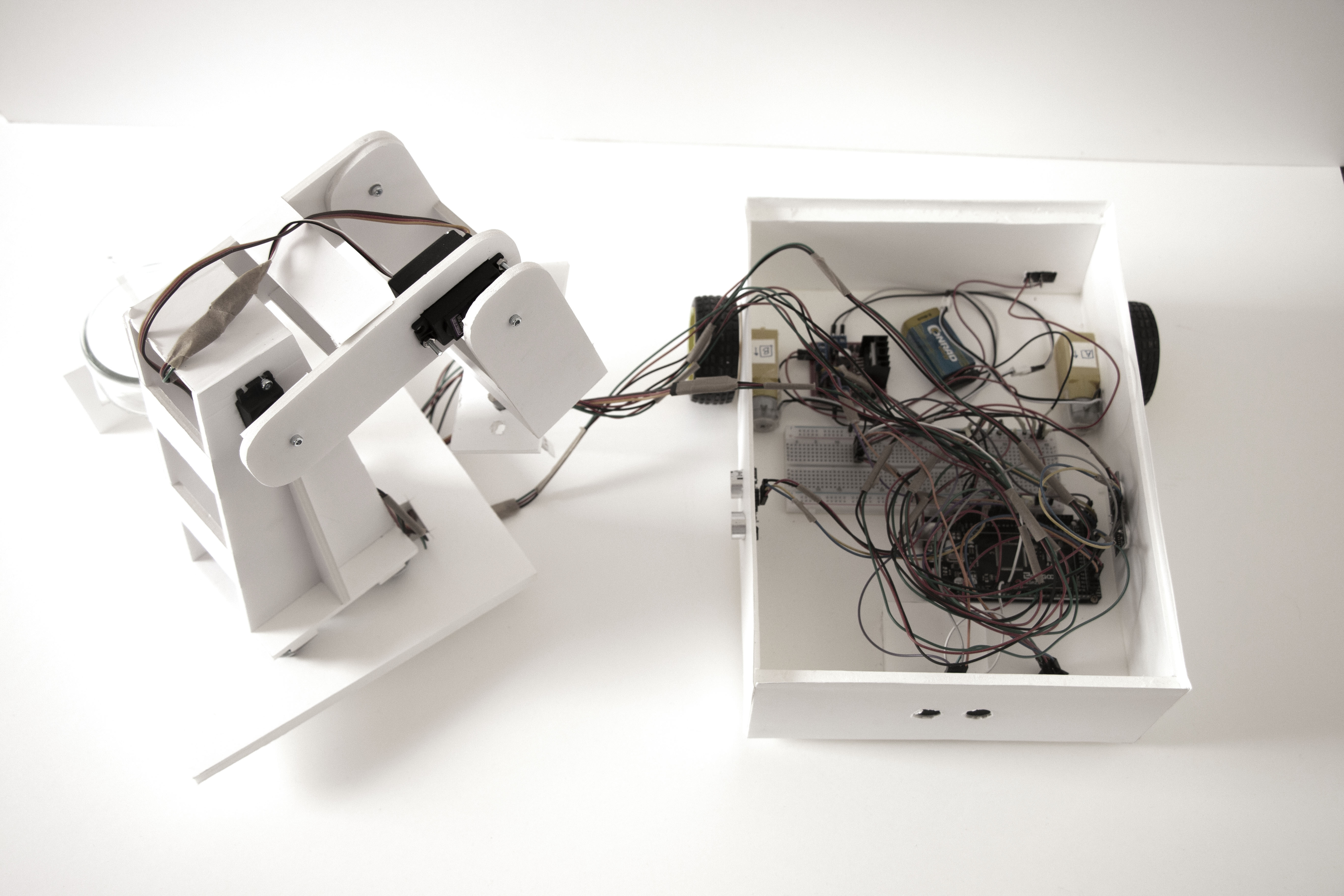
There are three chief parts of the painter: remotely steered robotic car, physically controlled 4-axis robotic arm and the main controller board. Those parts become a subsidiary to the Physical Twin for expressing its artistic side owing to not only its inherent movement possibilities but also the guidance of individuals.
Features
-By having a small physical twin, the robotic arm can learn from its twin’s movements that are controlled by humans and repeat those movements endlessly.
-With the aim of having a better control over the Physical Twin; train, record and play modes can be visualised by the LED lights.
-Angles of the axes can be displayed on the LCD Monitor.
-The wheels can be remotely controlled on the XY plane.
-The robot has the ability to get the distance data from its surrounding objects and avoid the obstacles.
-On and off switches on the controller and the robot car models are helpful for saving the batteries.
List of Parts
1. Electronics
1.1. Basics
Elegoo Mega 2560 R3 or Arduino Mega 2560 REV3 (x2)
330 Ohm Resistor (x4)
9V Battery (x2)
1.2. Sensors
HC-SR04 Ultrasonic Sensor (x3)
1.3. Motor-Related
MG996R Servo Motor (x4)
DC Motor (x2)
1.4. Controllers
Potentiometer (x5)
On-Off Switch (x2)
1.5. Display
LED Light (x3)
2. Mechanics
Foam Board (10 mm, 5 mm, 3 mm)
Back Wheel (x2)
Logic and Setup
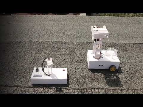
1. Robotic Arm
4 servo motors attached to the robotic arm represent the 4-axis of the robot. Smaller replica of the robotic arm on the controller board is called the physical twin and has 4 corresponding potentiometers which are responsible for the control of robotic arms’ angles.
When the physical twin is moved, each axis’ angle value is received from each potentiometer respectively, transferred to the NRF24L01 Module on the controller and sent to another Transceiver Module on the big robotic arm that is attached to the robotic car.
2. Robot Car
The robot car has 3 wheels in total, one small wheel in the front and 2 bigger wheels at the back. The car is remotely steered by the joystick on the controller board. In order to get the increasing motor speed value, the NRF24L01 Transceiver Module on the controller board transfers the X and Y-axis readings from the joystick to the Receiver Module that is connected to the 2 DC Motors of the bigger wheels. Inside the code, the joystick value is converted from 0 to 1023 into 0 to 255 value for PWM(Pulse-Width Modulation) signals.
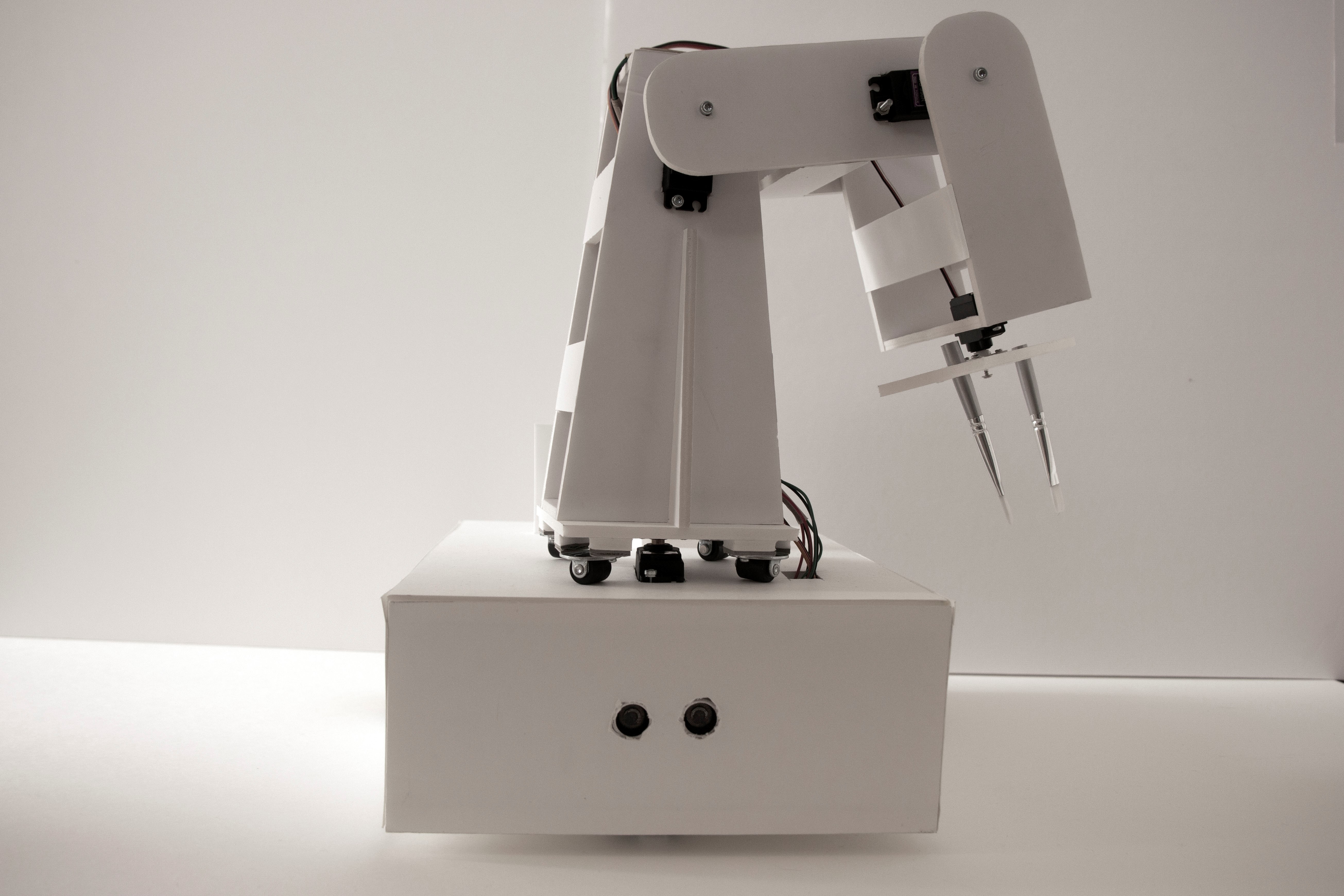
3 Ultrasonic Sensors for Distance Measuring are attached on the front, left and right sides of the car. Those sensors inform the movement of the motors considering the surrounding obstacles that are within the given limit. If the robot car gets too close to the objects around, the joystick does not transfer the data and the car stops in order to avoid collision.The battery of the motors can be switched on and off by using the button.
3. Controller Board
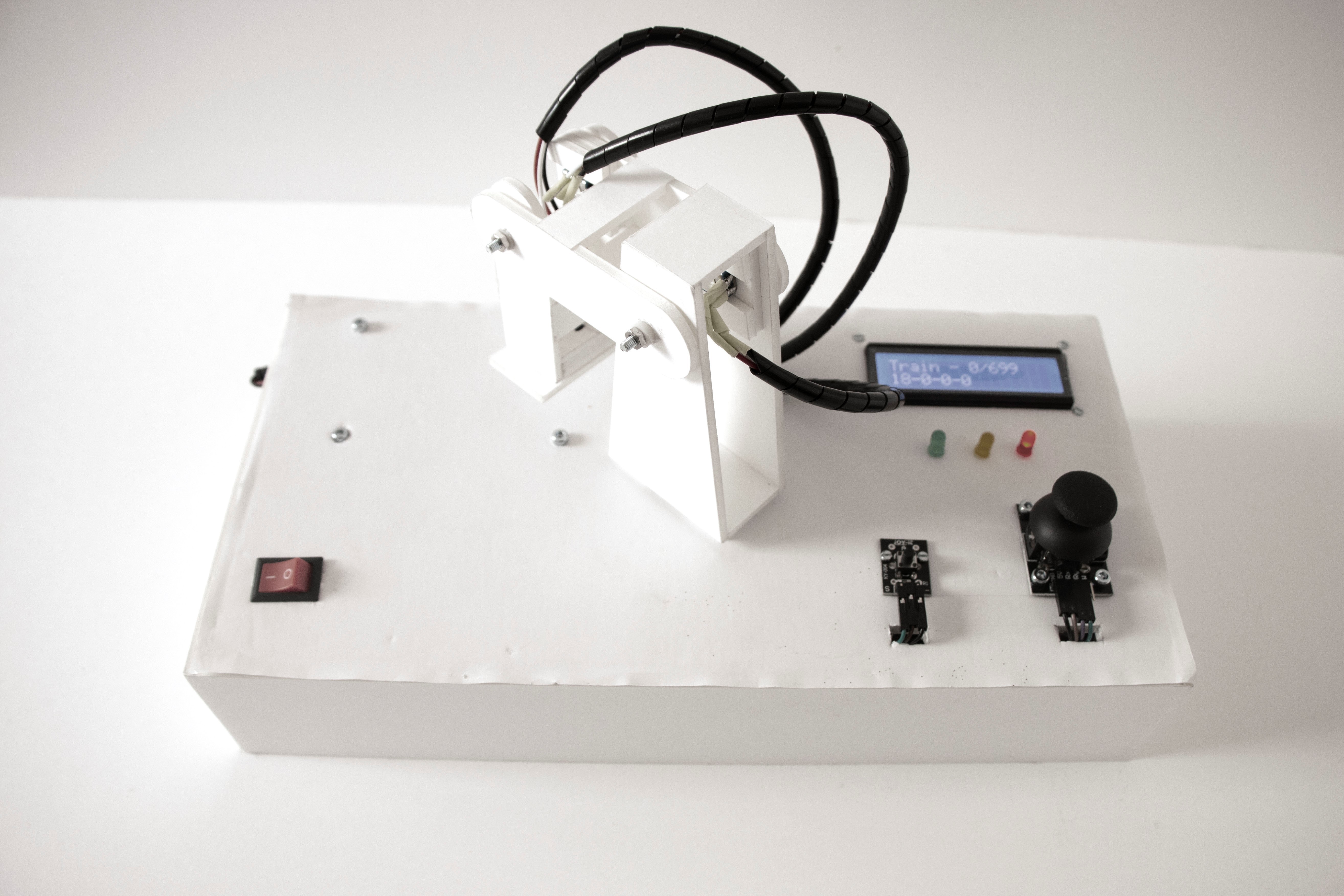
The controller board is the cockpit of our Physical Twin, which fundamentally includes a small physical twin of the robotic arm with 4 potentiometers attached to it, a joystick for the control of the car and an NRF24L01 Wireless Module for the transmission of the corresponding values. This board allows individuals to interact with the movement of the Physical Twin in order to control the axes of its arm by the potentiometers and move the car on the XY plane with the joystick. Additionally, the board includes an on-off switch button for saving the battery.
Assembling the Electronics
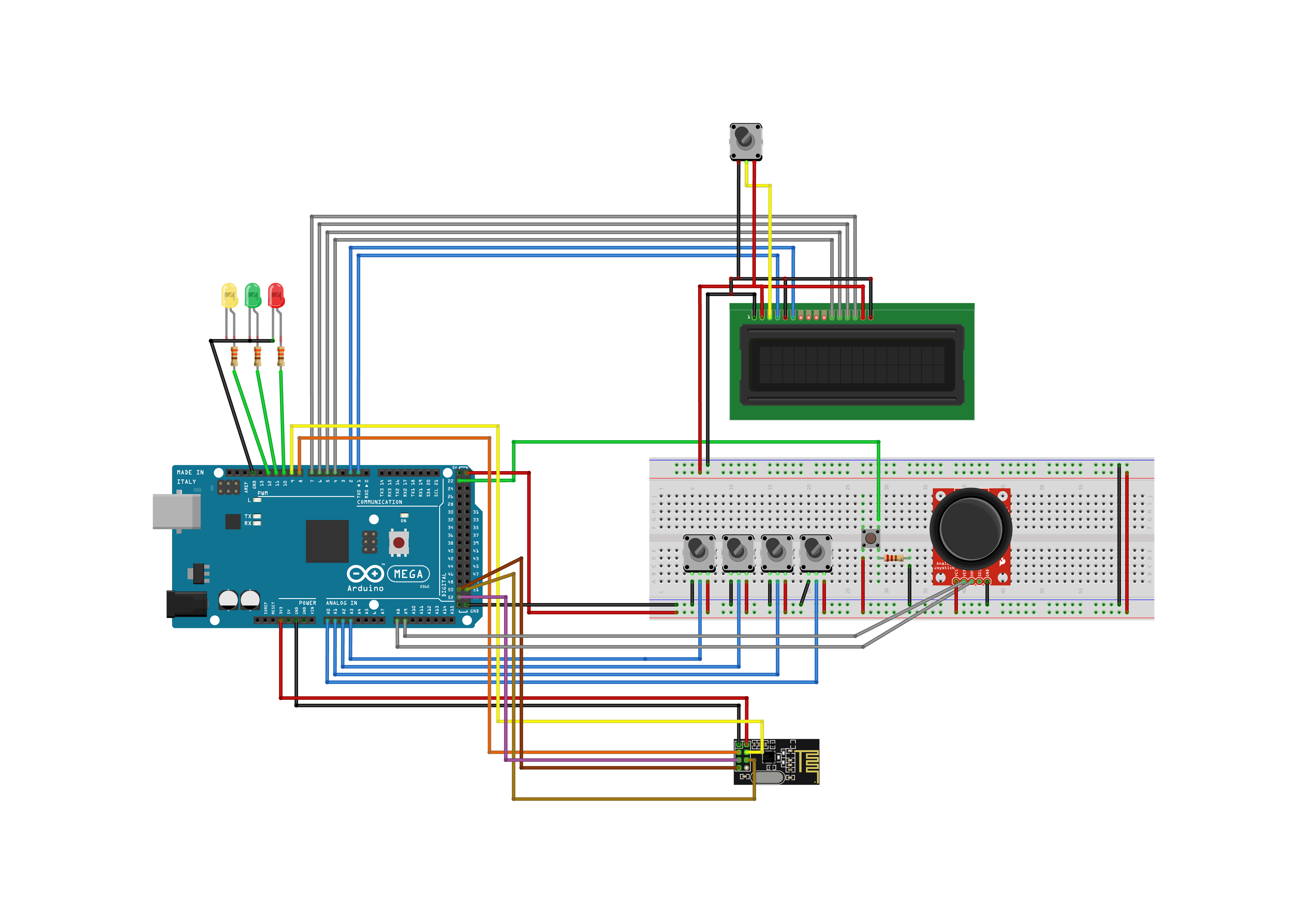
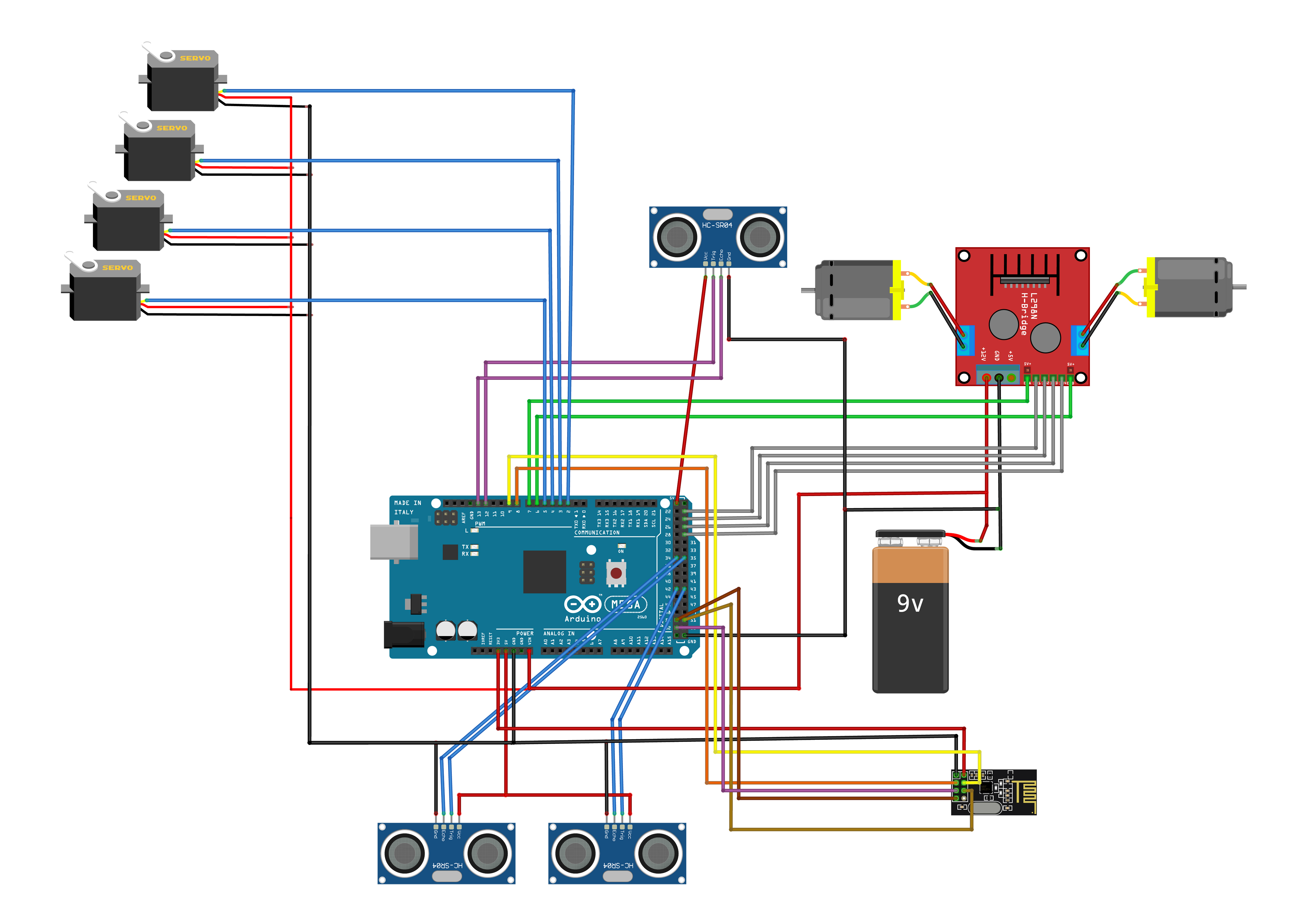
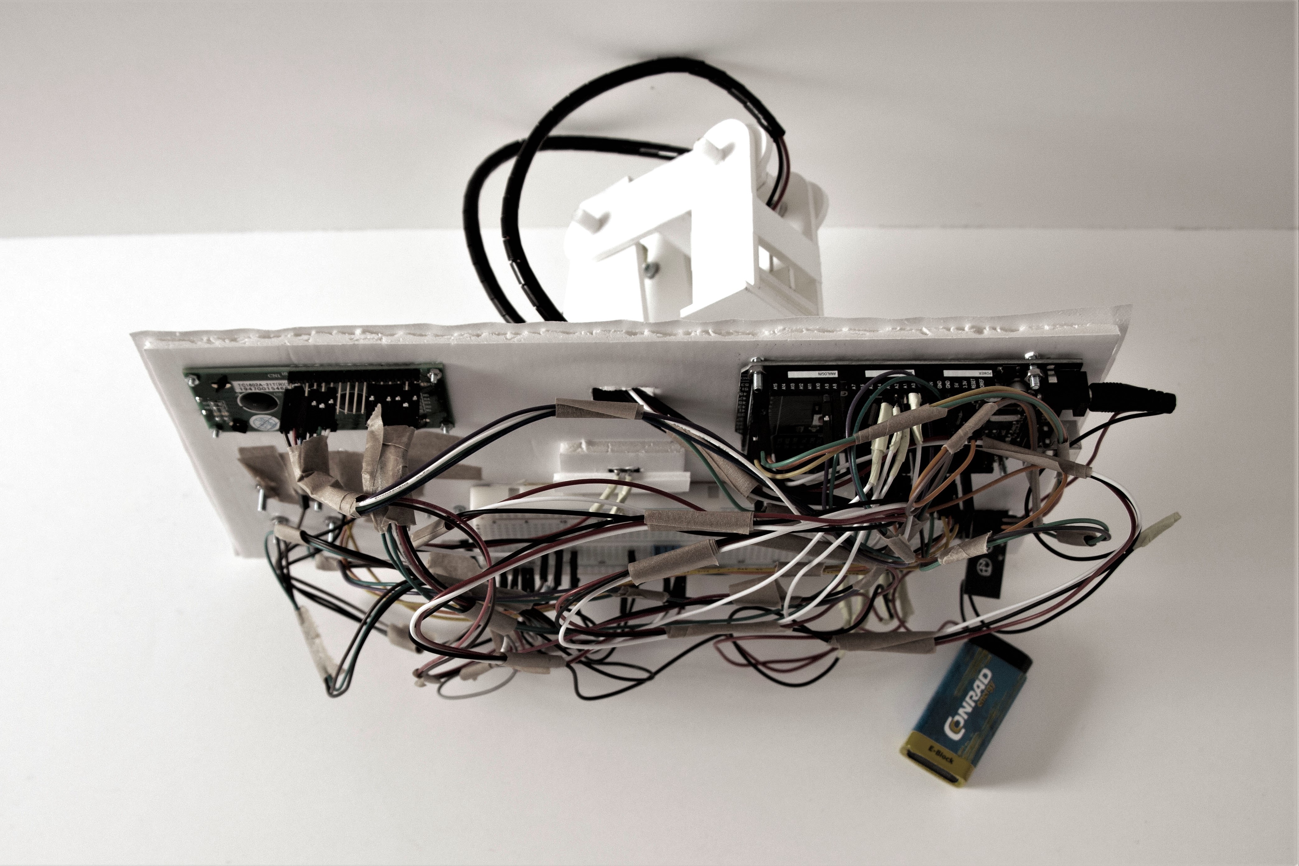
There are two main circuit diagrams of the Physical Twin project: the controller and the receiver.
1. The Controller Diagram
Each connection of the main modules in the controller diagram is explained as following:
NRF24L01 Wireless Transceiver Module as a Transmitter
NRF pin1: GND(Ground) connected to Arduino GND
NRF pin2: VCC(Voltage Common Collector) connected to Arduino 3.3 V
NRF pin3: CE(Data Transmission) connected to Arduino pin8
NRF pin4: CSN(Chip Select Not) connected to Arduino pin9
NRF pin5: SCK(Serial Clock) connected to Arduino pin52
NRF pin6: MOSI(Master Out Slave In) connected to Arduino pin51
NRF pin7: MISO(Master In Slave Out) connected to Arduino pin50
LCD Display Module
LCD pin1: GND(Ground) connected to Breadboard GND
LCD pin2: VCC(Voltage Common Collector) connected to Breadboard VCC, Potentiometer pin3: VCC and the LCD pin15: A(Anode)
LCD pin3: Vo(Display Contrast Pin) connected to Potentiometer pin2: Output
LCD pin4: RS(Register Select) connected to Arduino pin1
LCD pin5: RW(Read/Write) connected to LCD pin1: GND, Potentiometer pin1: GND, Breadboard GND, LCD pin16: K(Katode)
LCD pin6: E(Enable) connected to Arduino pin2
LCD pin11, 12, 13, 14: (Data Pins D4, D5, D6, D7) connected to Arduino pin4,5,6,7
Joystick
Joystick pin1: VCC(Voltage Common Collector) connected to Breadboard VCC
Joystick pin2: VER(Vertical) connected to Arduino Analog pin9: A9
Joystick pin3: HOR(Horizontal) connected to Arduino Analog pin8: A8
Joystick pin5: GND(Ground) connected to Breadboard GND
2. The Receiver Diagram
Each connection of the main modules in the receiver diagram is explained as following:
NRF24L01 Wireless Transceiver Module as a Receiver
NRF pin1: GND(Ground) connected to Arduino GND and Servo Motors’ GND
NRF pin2: VCC(Voltage Common Collector) connected to Arduino 3.3 V
NRF pin3: CE(Data Transmission) connected to Arduino pin8
NRF pin4: CSN(Chip Select Not) connected to Arduino pin9
NRF pin5: SCK(Serial Clock) connected to Arduino pin52
NRF pin6: MOSI(Master Out Slave In) connected to Arduino pin51
NRF pin7: MISO(Master In Slave Out) connected to Arduino pin50
L298N H-Bridge
H-Bridge Motor A pin1: VCC(Voltage Common Collector) connected to DC Motor A VCC
H-Bridge Motor A pin2: GND(Ground) connected to DC Motor A GND
H-Bridge Motor B pin1: VCC(Voltage Common Collector) connected to DC Motor B VCC
H-Bridge Motor B pin2: GND(Ground) connected to DC Motor B GND
H-Bridge pin1: VCC(Voltage Common Collector) connected to Battery VCC
H-Bridge pin2: GND(Ground) connected to Battery GND
H-Bridge pin4: Motor A Control Pin connected to Arduino pin7
H-Bridge pin5: Motor A Clockwise connected to Arduino pin23
H-Bridge pin6: Motor A Counterclockwise connected to Arduino pin25
H-Bridge pin7: Motor B Clockwise connected to Arduino pin27
H-Bridge pin8: Motor B Counterclockwise connected to Arduino pin29
H-Bridge pin9: Motor B Control Pin connected to Arduino pin6
HC-SR04 Ultrasonic Sensor
Sensor1:
Ultrasonic1 pin1: VCC(Voltage Common Collector) connected to Arduino VCC
Ultrasonic1 pin2: TRIG(Signal Output) connected to Arduino pin12
Ultrasonic1 pin3: ECHO(Signal Input) connected to Arduino pin13
Ultrasonic1 pin4: GND(Ground) connected to Arduino GND
Sensor2:
Ultrasonic2 pin1: VCC(Voltage Common Collector) connected to Ultrasonic3 pin1: VCC and Arduino VCC
Ultrasonic2 pin2: TRIG(Signal Output) connected to Arduino pin35
Ultrasonic2 pin3: ECHO(Signal Input) connected to Arduino pin34
Ultrasonic2 pin4: GND(Ground) connected to Ultrasonic3 pin4: GND, Servo Motors’ GND, NRF pin1: GND and Arduino GND
Sensor3:
Ultrasonic3 pin1: VCC(Voltage Common Collector) connected to Ultrasonic2 pin1: VCC and Arduino VCC
Ultrasonic3 pin2: TRIG(Signal Output) connected to Arduino pin43
Ultrasonic3 pin3: ECHO(Signal Input) connected to Arduino pin42
Ultrasonic3 pin4: GND(Ground) connected to Ultrasonic2 pin4: GND, Servo Motors’ GND, NRF pin1: GND and Arduino GND
Code
Physical Twin has two main codes: one for the controller board, another for the robot car with a painter robotic arm.The explanations of the essential lines are embedded inside codes.
The complete code of the controller:
#include <LiquidCrystal.h>
#include <SPI.h>
#include <nRF24L01.h>
#include <RF24.h>

//nRF pin setup
RF24 radio(8, 9);
const byte address[6] = "00001";

union packet {
  float vals[6];
  byte bytes[4];
} dataPacket;

//LCD pin setup
LiquidCrystal lcd(1, 2, 4, 5, 6, 7);

//LEDS pin setup
int redLed = 10;
int yellowLed = 11;
int greenLed = 12;

//JOYSTICK pin setup
int xAxis = A8;
int yAxis = A9;
int count;

//Potentiometer pin setup
int sensorPin0 = A0;
int sensorPin1 = A1;
int sensorPin2 = A2;
int sensorPin3 = A3;


int arrayStep, arrayMax, Tester, maxStep; // arrayStep-location in the array, arrayMax - maximum number in the array, Tester - switch states, maxStep - help to remap the steps

// Time steps to calculate steps
long previousMillis1 = 0;
long previousMillis2 = 0;
unsigned long currentMillis = millis();
unsigned long currentMicros = micros();

// array to keep sensor values
int SensVal[4];

// arrays to calculate to movment while in play mode
float  dirs[4], stepsCount[4], ist[4], Home[4], steps[4], previousSteps[4], CurrentPos[4];

// arrays to store all of the movments
int joint0[500];
int joint1[500];
int joint2[500];
int joint3[500];

int top = 499;
boolean playmode = false;


void setup() {

  pinMode(22, INPUT); //button

  //setup for nRF
  radio.begin();
  radio.openWritingPipe(address);
  radio.setPALevel(RF24_PA_MIN);
  radio.stopListening();

  //setup for leds
  pinMode(redLed, OUTPUT);
  pinMode(yellowLed, OUTPUT);
  pinMode(greenLed, OUTPUT);

  //setup for lcd
  lcd.begin(16, 2);
  lcd.print("Physical-Twin");
  delay(2000);

}

void loop() {

  currentMillis = millis();
  currentMicros = micros();

  Button(); //Get current state

  if (!playmode) {
    digitalWrite(redLed, HIGH);
    digitalWrite(greenLed, LOW);
    lcd.setCursor(0, 0);
    if (Tester == 1) {
      digitalWrite(yellowLed, HIGH);
      lcd.print("Recording  -  ");
    }
    else {
      digitalWrite(yellowLed, LOW);
      lcd.print("Train - "); lcd.print(arrayMax); lcd.print("/"); lcd.print(top); lcd.print("    ");
    }
    if (currentMillis - previousMillis1 > 25) {
      if (arrayStep < top) {

        previousMillis1 = currentMillis; //reset
        readPot(); //read the minirobot data
        mapping(); //map the values
        record(); //record the values


        lcd.setCursor(0, 1);
        lcd.print((int)ist[0]);
        lcd.print("-");
        lcd.print((int)ist[1]);
        lcd.print("-");
        lcd.print((int)ist[2]);
        lcd.print("-");
        lcd.print((int)ist[3]);
        lcd.print("            ");

        //setting the values to send to the receiver
        dataPacket.vals[0] = analogRead(xAxis);
        dataPacket.vals[1] = analogRead(yAxis);
        dataPacket.vals[2] = ist[0];
        dataPacket.vals[3] = ist[1];
        dataPacket.vals[4] = ist[2];
        dataPacket.vals[5] = ist[3];

        radio.write(&dataPacket.vals, sizeof(dataPacket.vals)); //send movment to receiver
      }
    }
  }

  else if (playmode) {

    digitalWrite(redLed, LOW);
    digitalWrite(yellowLed, LOW);
    digitalWrite(greenLed, HIGH);
    lcd.setCursor(0, 0);

    if (arrayStep < arrayMax) {
      Read();
      play();
      arrayStep++;
      delay(100); //set back to 10 when plugin everything
    }
    else {
      ist[0] = joint0[0], ist[1] = joint1[0], ist[2] = joint2[0], ist[3] = joint3[0];
      play();
      arrayStep = 0;
      delay(1000);
    }

    lcd.print("Play - "); lcd.print(arrayStep); lcd.print("/"); lcd.print(arrayMax); lcd.print("     ");
  }
}

void readPot() {
  SensVal[0] = analogRead(sensorPin0);
  SensVal[1] = analogRead(sensorPin1);
  SensVal[2] = analogRead(sensorPin2);
  SensVal[3] = analogRead(sensorPin3);
}

void mapping() {
  ist[0] = map(SensVal[0], 0, 1023, 0, 180);
  ist[1] = map(SensVal[1], 0, 1023, 0, 180);
  ist[2] = map(SensVal[2], 0, 1023, 0, 180);
  ist[3] = map(SensVal[3], 0, 1023, 0, 180);
}

void record() {
  joint0[arrayStep] = ist[0];
  joint1[arrayStep] = ist[1];
  joint2[arrayStep] = ist[2];
  joint3[arrayStep] = ist[3];
}

void Read() {
  ist[0] = joint0[arrayStep];
  ist[1] = joint1[arrayStep];
  ist[2] = joint2[arrayStep];
  ist[3] = joint3[arrayStep];
}


void Button() {

  if (digitalRead(22) == false) {

    delay(100);

    if (digitalRead(22) == true) { //first click to run record

      if (Tester == 0) {
        Tester = 1;
        previousMillis2 = currentMillis;
      }

      else if ((Tester == 1) && (currentMillis - previousMillis2 < 1500)) //double click to start playmode
      {
        Tester = 2;
      }

      if (playmode) {
        arrayStep = 0;
        arrayMax = 0;
        Tester = 0;
        resetArrays();
        playmode = false;
      }
    }
  }

  if (Tester == 1) { //Record Mode
    arrayStep += 1;
    arrayMax = arrayStep;
    playmode = false;
    lcd.setCursor(11, 0);
    lcd.print(arrayStep);
    delay(100);
  }
  else if (Tester == 2) {
    arrayStep = 0 ;
    previousSteps[0] = joint0[0];
    previousSteps[1] = joint1[0];
    previousSteps[2] = joint2[0];
    previousSteps[3] = joint3[0];
    playmode = true;
  }

  if (currentMillis - previousMillis2 > 2000) // button Status clear
  {
    Tester = 0;
  }
}

void resetArrays() {
  for (int i = 0; i < top; i++) {
    joint0[i] = 0;
    joint1[i] = 0;
    joint2[i] = 0;
    joint3[i] = 0;
  }
}

void play() {
  steps[0] = ist[0] - previousSteps[0];
  steps[1] = ist[1] - previousSteps[1];
  steps[2] = ist[2] - previousSteps[2];
  steps[3] = ist[3] - previousSteps[3];

  maxStep = max(abs(steps[0]), abs(steps[1]));
  maxStep = max(maxStep, abs(steps[2]));
  maxStep = max(maxStep, abs(steps[3]));

  stepsCount[0] = previousSteps[0], stepsCount[1] = previousSteps[1], stepsCount[2] = previousSteps[2], stepsCount[3] = previousSteps[3];


  dirs[0] = steps[0] / maxStep;
  dirs[1] = steps[1] / maxStep;
  dirs[2] = steps[2] / maxStep;
  dirs[3] = steps[3] / maxStep;

  for (int i = 0; i < maxStep - 1; i++) {

    stepsCount[0] = stepsCount[0] + dirs[0];
    stepsCount[1] = stepsCount[1] + dirs[1];
    stepsCount[2] = stepsCount[2] + dirs[2];
    stepsCount[3] = stepsCount[3] + dirs[3];

    lcd.setCursor(0, 1);
    lcd.print((int)stepsCount[0]);
    lcd.print("-");
    lcd.print((int)stepsCount[1]);
    lcd.print("-");
    lcd.print((int)stepsCount[2]);
    lcd.print("-");
    lcd.print((int)stepsCount[3]);
    lcd.print("            ");

    dataPacket.vals[0] = analogRead(xAxis);
    dataPacket.vals[1] = analogRead(yAxis);
    dataPacket.vals[2] = stepsCount[0];
    dataPacket.vals[3] = stepsCount[1];
    dataPacket.vals[4] = stepsCount[2];
    dataPacket.vals[5] = stepsCount[3];

    radio.write(&dataPacket.vals, sizeof(dataPacket.vals));

    delay(35);
  }
  previousSteps[0] = ist[0];
  previousSteps[1] = ist[1];
  previousSteps[2] = ist[2];
  previousSteps[3] = ist[3];
}<br>
The complete code of the receiver:
#include <Servo.h>
#include <SPI.h>
#include <nRF24L01.h>
#include <RF24.h>

//nRF pin setup
RF24 radio(8, 9);
const byte address[6] = "00001";

union packet {
  float vals[6];
  byte bytes[4];
} dataPacket;

//Servo pin setup
Servo servo_1;
Servo servo_2;
Servo servo_3;
Servo servo_4;

//DC motors pin setup
int enA = 6;
int in1 = 23;
int in2 = 25;
int enB = 7;
int in3 = 27;
int in4 = 29;

// x and y values and speed for dc motors
int  xAxis, yAxis;
int motorSpeedA = 0;
int motorSpeedB = 0;

// set ultrasonic sensors pin mode
const int FrontTrig = 43;
const int FrontEcho = 42;

const int RightTrig = 12;
const int RightEcho = 13;

const int LeftTrig = 35;
const int LeftEcho = 34;

int distance1;
int distance2;
int distance3;

void setup() {

  //setup for nRF
  radio.begin();
  radio.openReadingPipe(0, address);
  radio.setPALevel(RF24_PA_MIN);
  radio.startListening();

  //attaches the servos
  servo_1.attach(2);
  servo_2.attach(3);
  servo_3.attach(4);
  servo_4.attach(5);

  //setup for hBridge
  pinMode(enA, OUTPUT);
  pinMode(enB, OUTPUT);
  pinMode(in1, OUTPUT);
  pinMode(in2, OUTPUT);
  pinMode(in3, OUTPUT);
  pinMode(in4, OUTPUT);

  pinMode(FrontTrig, OUTPUT); // Sets the trigPin as an Output
  pinMode(FrontEcho, INPUT); // Sets the echoPin as an Input

  pinMode(RightTrig, OUTPUT); // Sets the trigPin as an Output
  pinMode(RightEcho, INPUT); // Sets the echoPin as an Input

  pinMode(LeftTrig, OUTPUT); // Sets the trigPin as an Output
  pinMode(LeftEcho, INPUT); // Sets the echoPin as an Input
  Serial.begin(9600);

}

void loop() {

  // checking for distances
  distance1 = checkDistSensors(FrontTrig, FrontEcho);
  distance2 = checkDistSensors(RightTrig, RightEcho);
  distance3 = checkDistSensors(LeftTrig, LeftEcho);

  Serial.print(distance1);
  Serial.print("--");
  Serial.print(distance2);
  Serial.print("--");
  Serial.println(distance3);

  if (radio.available())
  {
    radio.read(&dataPacket.vals, sizeof(dataPacket.vals));
    xAxis = 500;
    yAxis = 500;

    if (distance1 > 12) {
      yAxis = dataPacket.vals[1];
      if (distance2 > 5 && distance3 > 5 ) {

        servo_1.write(dataPacket.vals[2]);
        servo_2.write(dataPacket.vals[3]);
        servo_3.write(dataPacket.vals[4]);
        servo_4.write(dataPacket.vals[5]);

        xAxis = dataPacket.vals[0];
      }
    }
    else if (distance2 > 5 && distance3 > 5 ) {
      xAxis = dataPacket.vals[0];
    }
    runMotors();
  }
}


int checkDistSensors(int trig, int echo) {

  digitalWrite(trig, LOW);
  delayMicroseconds(2);
  digitalWrite(trig, HIGH);
  delayMicroseconds(10);
  digitalWrite(trig, LOW);
  long duration = pulseIn(echo, HIGH);
  int distance = duration * 0.034 / 2;

  return distance;
}

void  runMotors() {

  //___MOTORS___
  //___Y-AXIS: FORWARD AND BACKWARD___
  if (yAxis < 470) {

    //-Y1. BACKWARD
    //--Motor A backward
    digitalWrite(in1, HIGH);
    digitalWrite(in2, LOW);

    //--Motor B backward
    digitalWrite(in3, HIGH);
    digitalWrite(in4, LOW);

    //--Convert
    motorSpeedA = map(yAxis, 470, 0, 0, 255);
    motorSpeedB = map(yAxis, 470, 0, 0, 255);
  }

  //-Y2. FORWARD
  else if (yAxis > 550) {
    //--Motor A forward
    digitalWrite(in1, LOW);
    digitalWrite(in2, HIGH);
    //--Motor B forward
    digitalWrite(in3, LOW);
    digitalWrite(in4, HIGH);

    //--Convert
    motorSpeedA = map(yAxis, 550, 1023, 0, 255);
    motorSpeedB = map(yAxis, 550, 1023, 0, 255);
  }

  //-Y3. MIDDLE
  //--Joystick in middle
  else {
    motorSpeedA = 0;
    motorSpeedB = 0;
  }

  //___X AXIS: LEFT AND RIGHT___

  if (xAxis < 470) {

    //-X1. LEFT

    //--Convert
    int xMapped = map(xAxis, 470, 0, 0, 255);

    //--Move to left - decrease left motor speed, increase right motor speed
    motorSpeedA = motorSpeedA - xMapped;
    motorSpeedB = motorSpeedB + xMapped;

    //--Limit the range from 0 to 255
    if (motorSpeedA < 0) {
      motorSpeedA = 0;
    }
    if (motorSpeedB > 255) {
      motorSpeedB = 255;
    }
  }

  //-X2. RIGHT

  if (xAxis > 550) {

    //--Convert
    int xMapped = map(xAxis, 550, 1023, 0, 255);

    //--Move right - decrease right motor speed, increase left motor speed
    motorSpeedA = motorSpeedA + xMapped;
    motorSpeedB = motorSpeedB - xMapped;

    //--Limit the range from 0 to 255
    if (motorSpeedA > 255) {
      motorSpeedA = 255;
    }
    if (motorSpeedB < 0) {
      motorSpeedB = 0;
    }
  }

  //___PREVENT BUZZING (at low speeds)___
  if (motorSpeedA < 70) {
    motorSpeedA = 0;
  }
  if (motorSpeedB < 70) {
    motorSpeedB = 0;
  }

  //___PWM SIGNALS TO MOTORS___
  analogWrite(enA, motorSpeedA);
  analogWrite(enB, motorSpeedB);
}<br>Design, Fabrication and Assembly
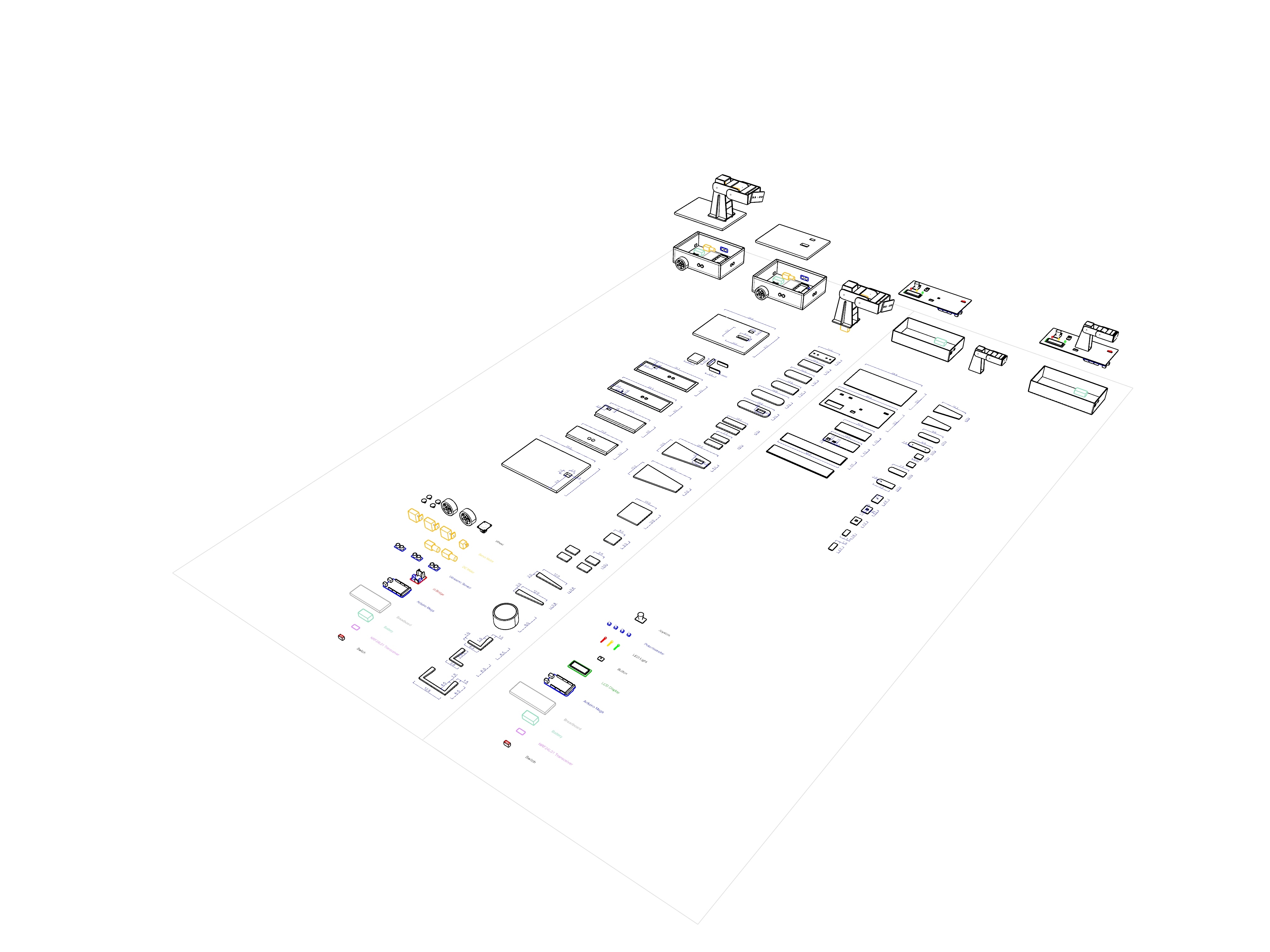
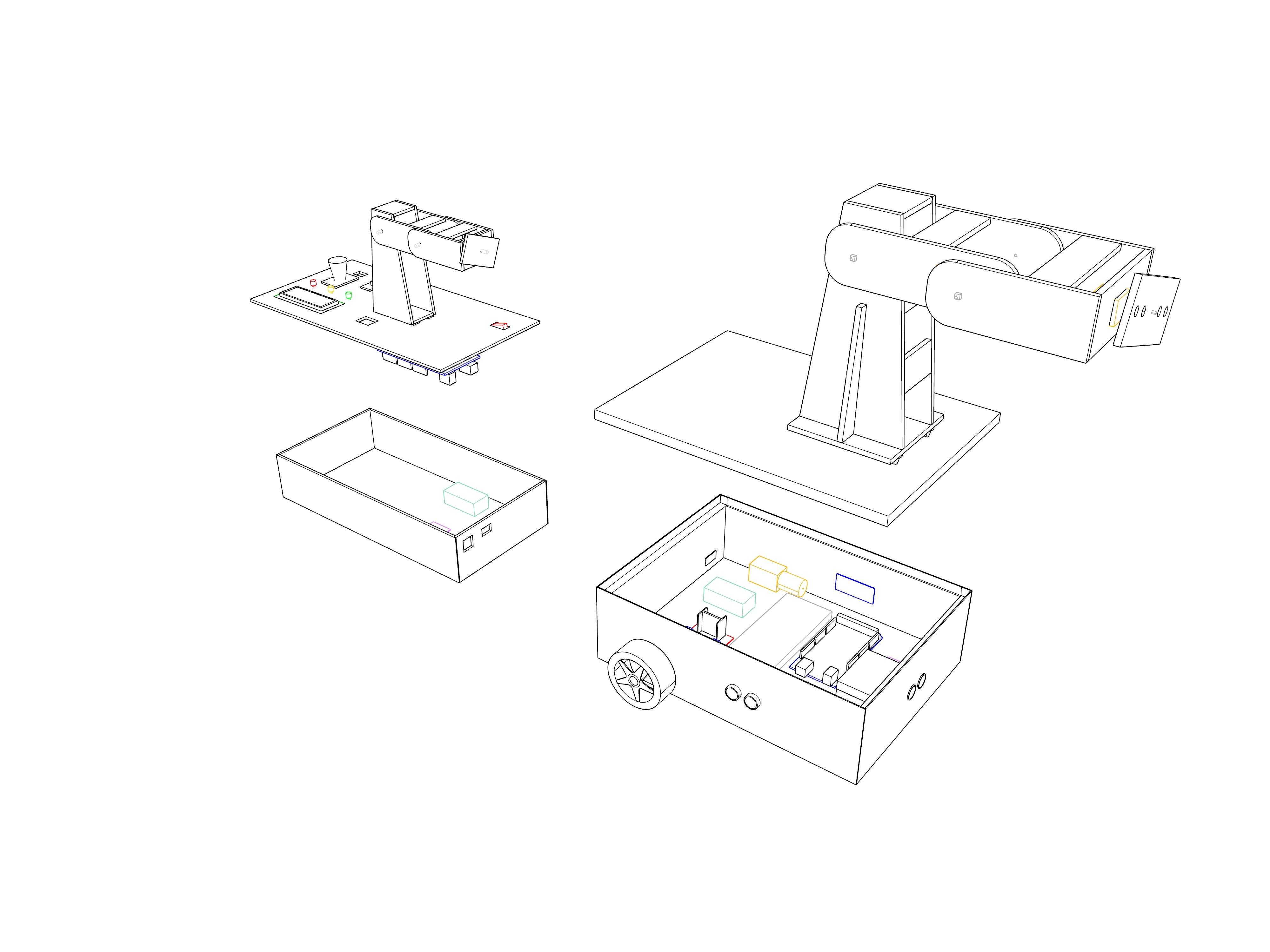
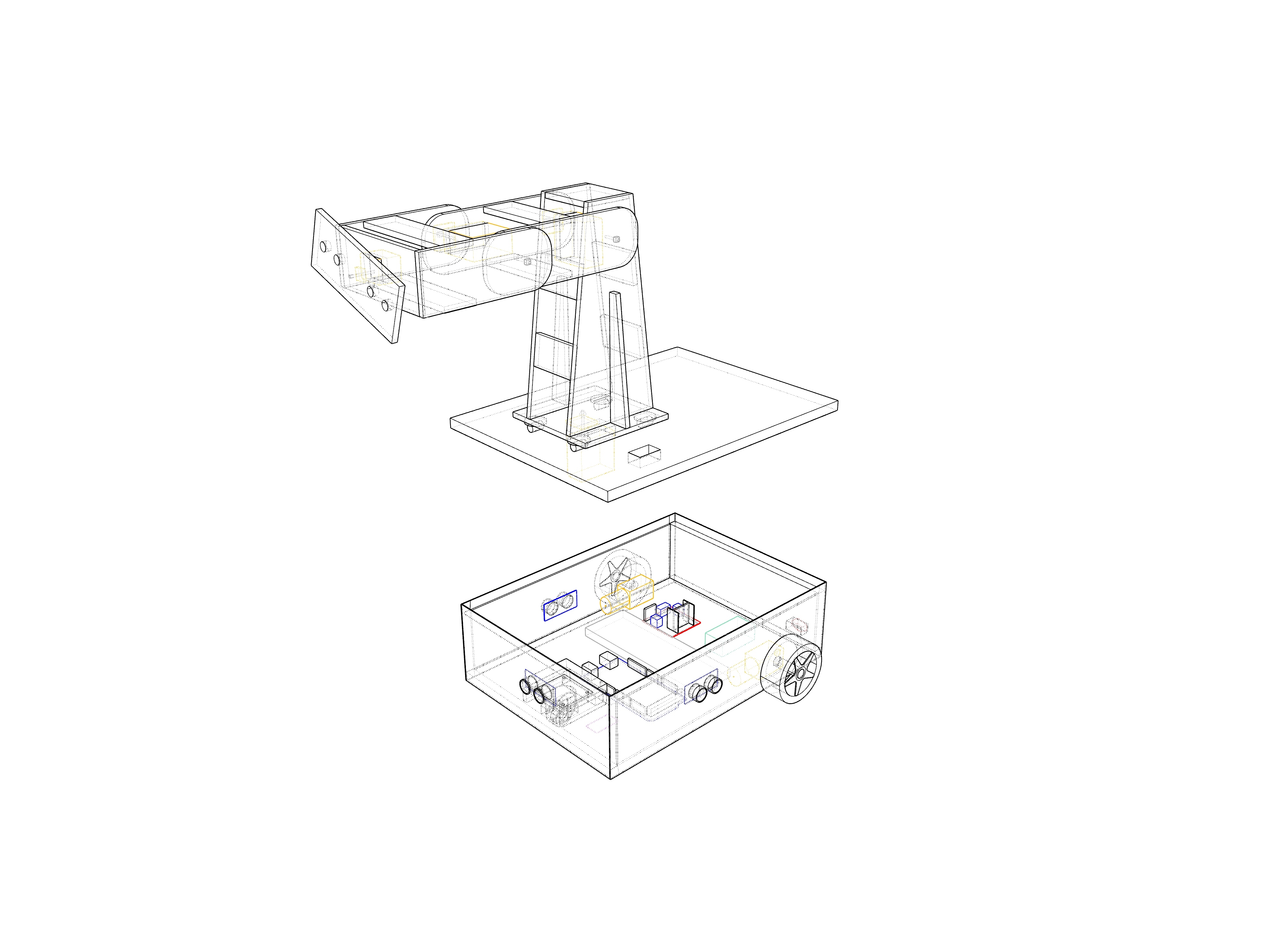
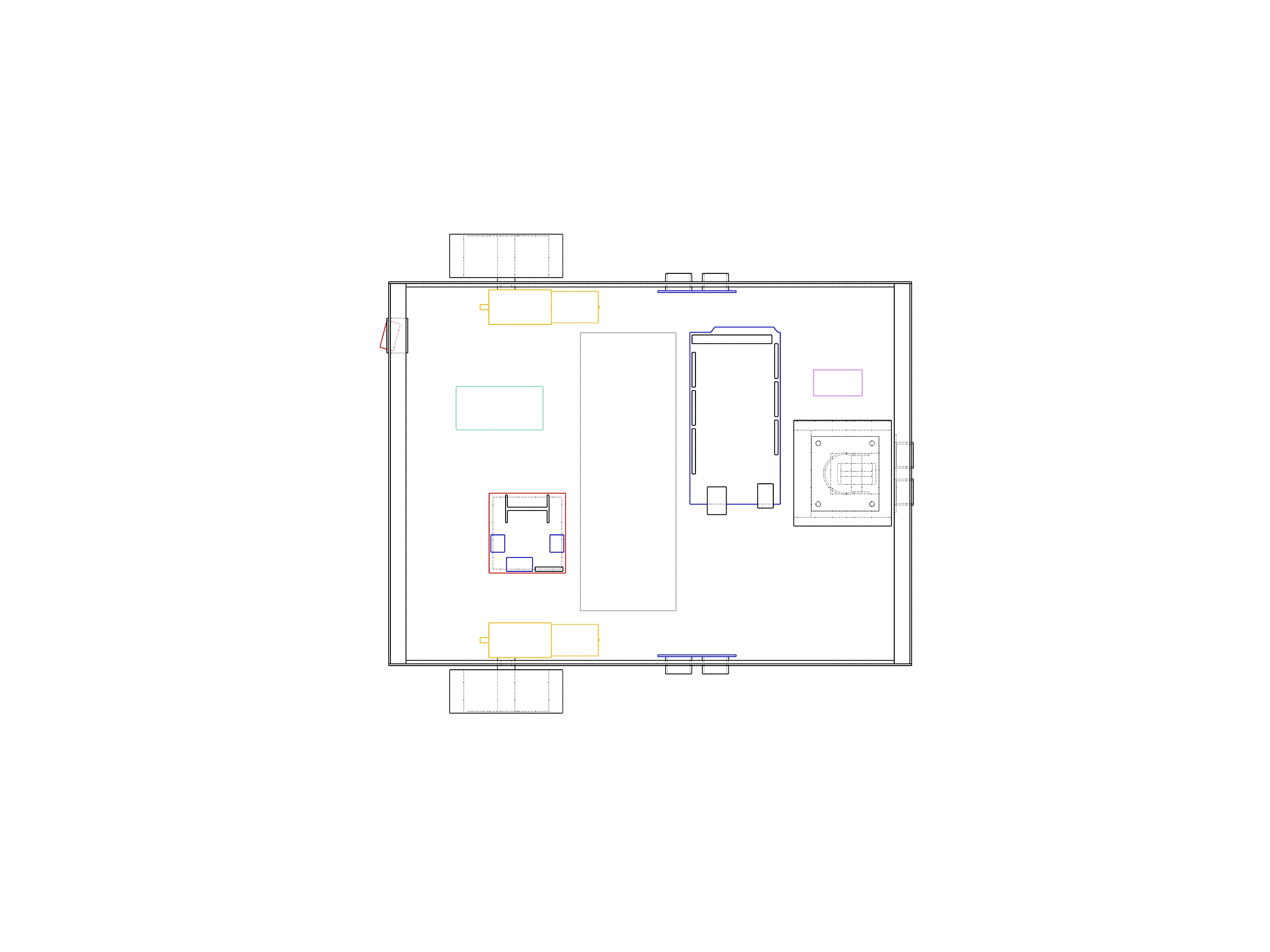
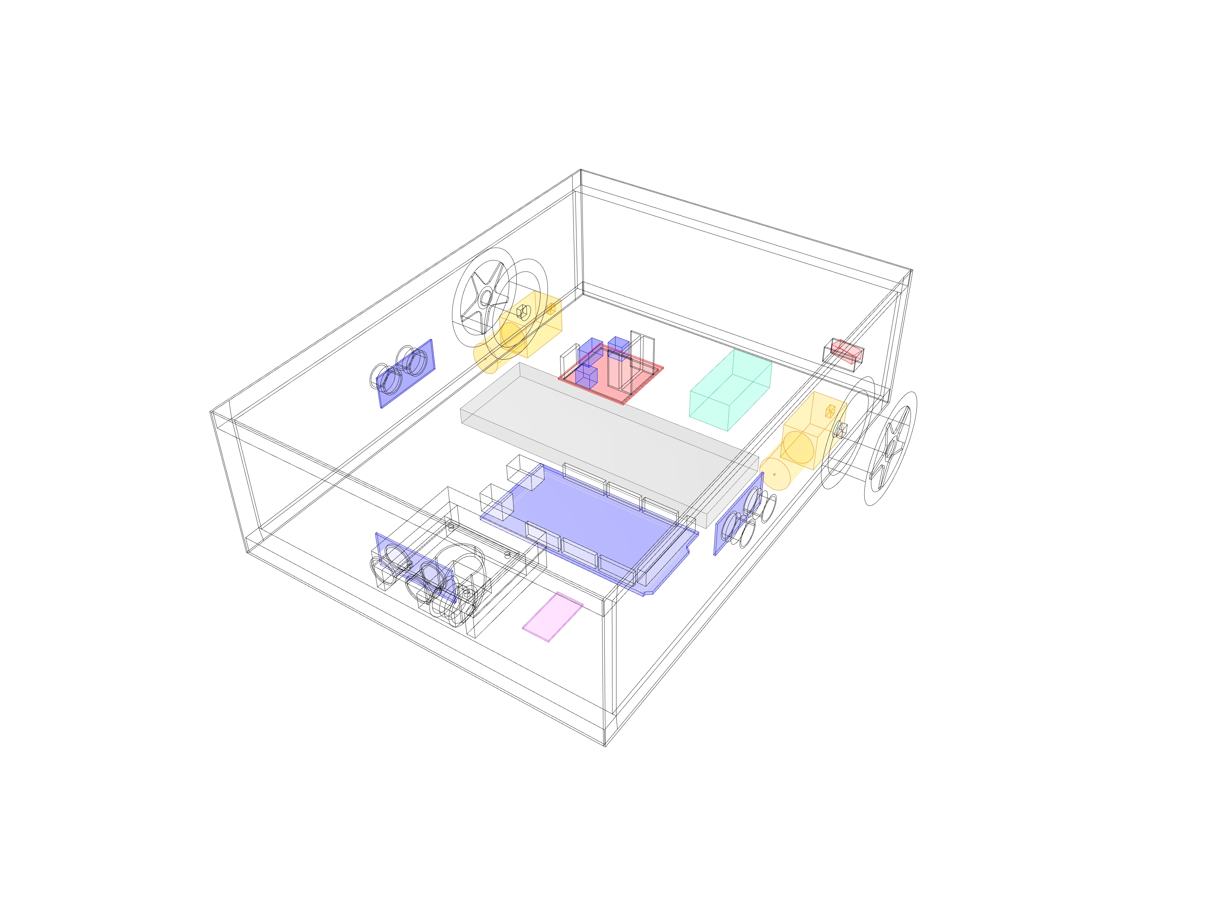
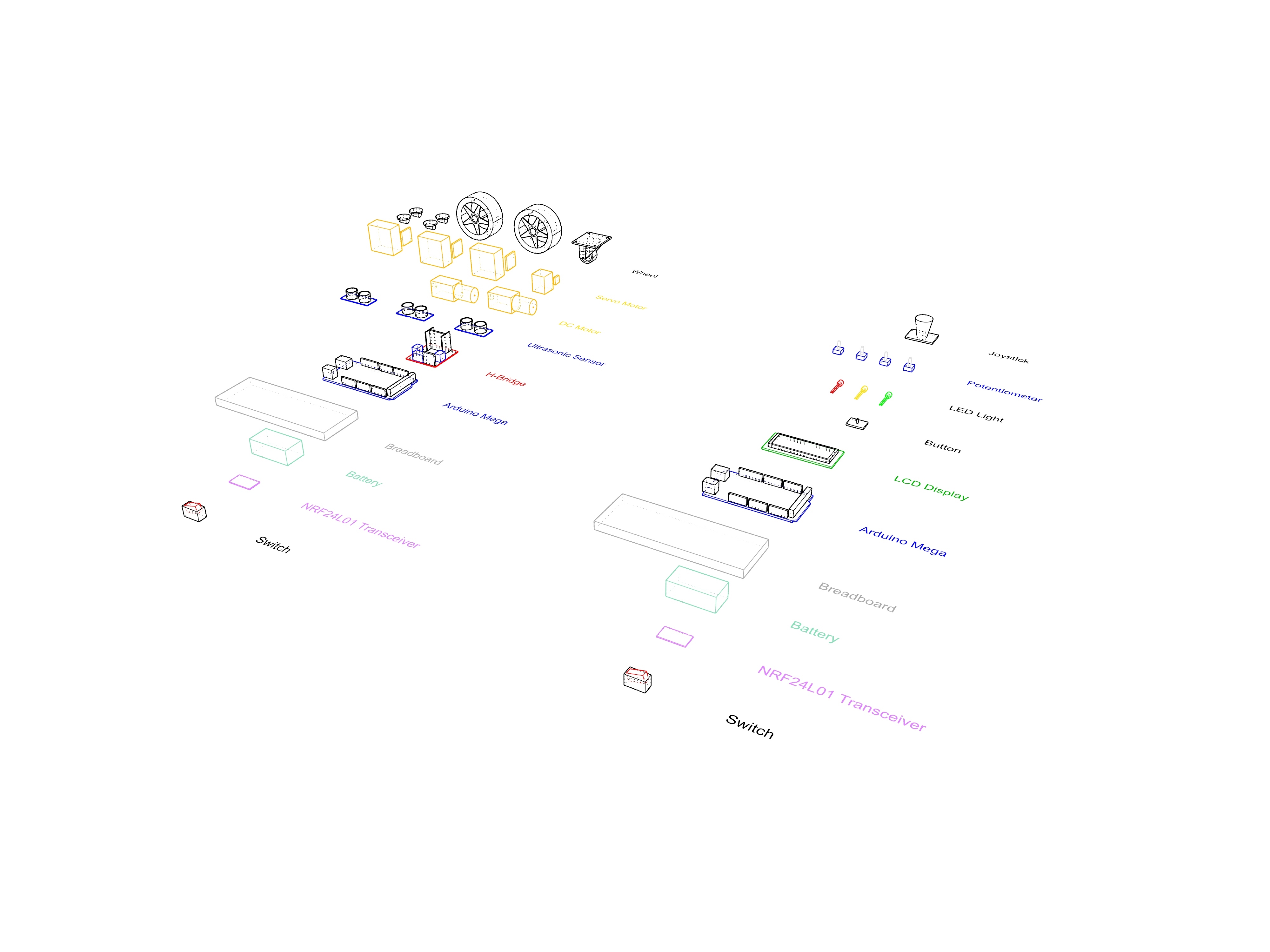
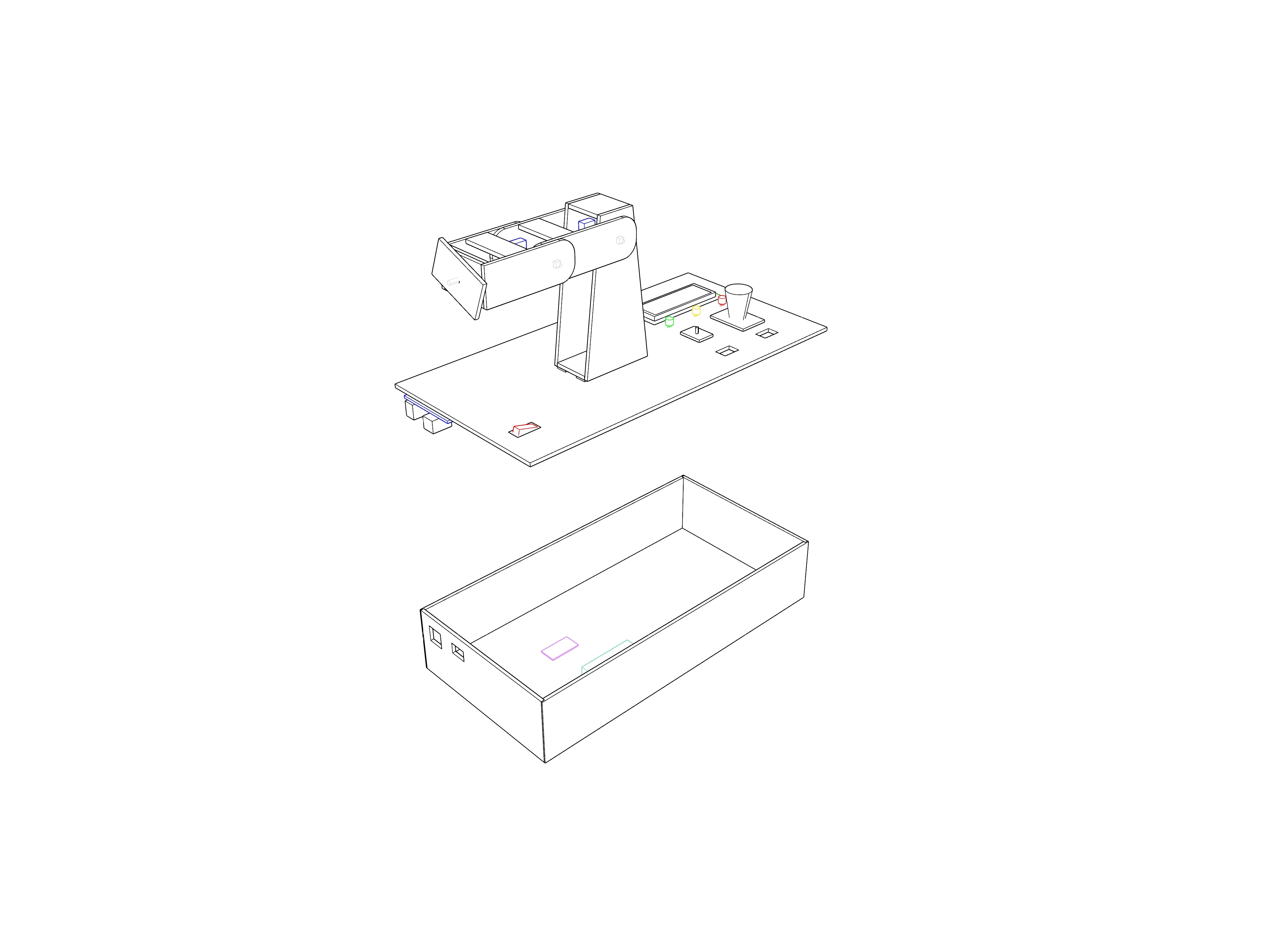
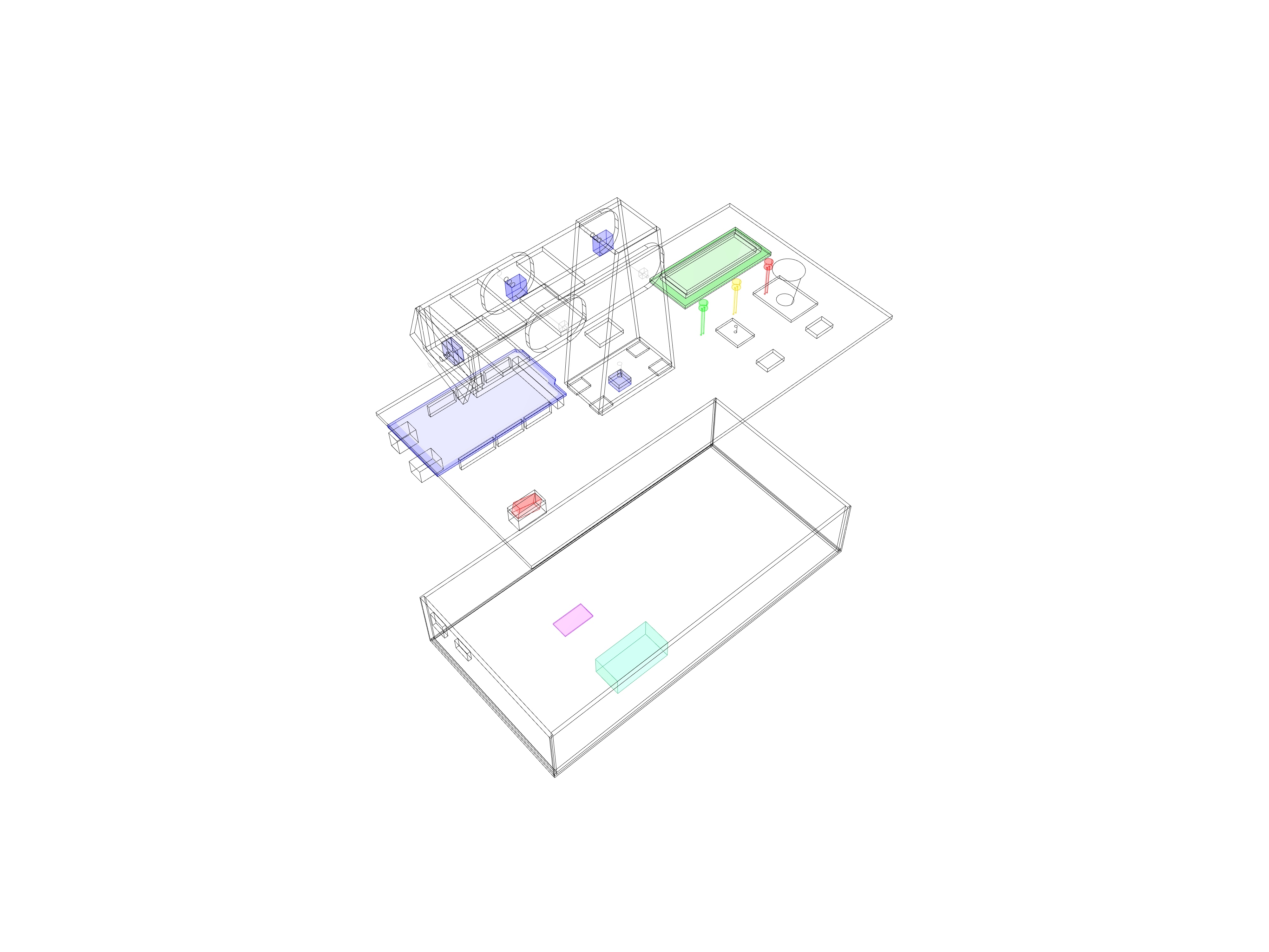
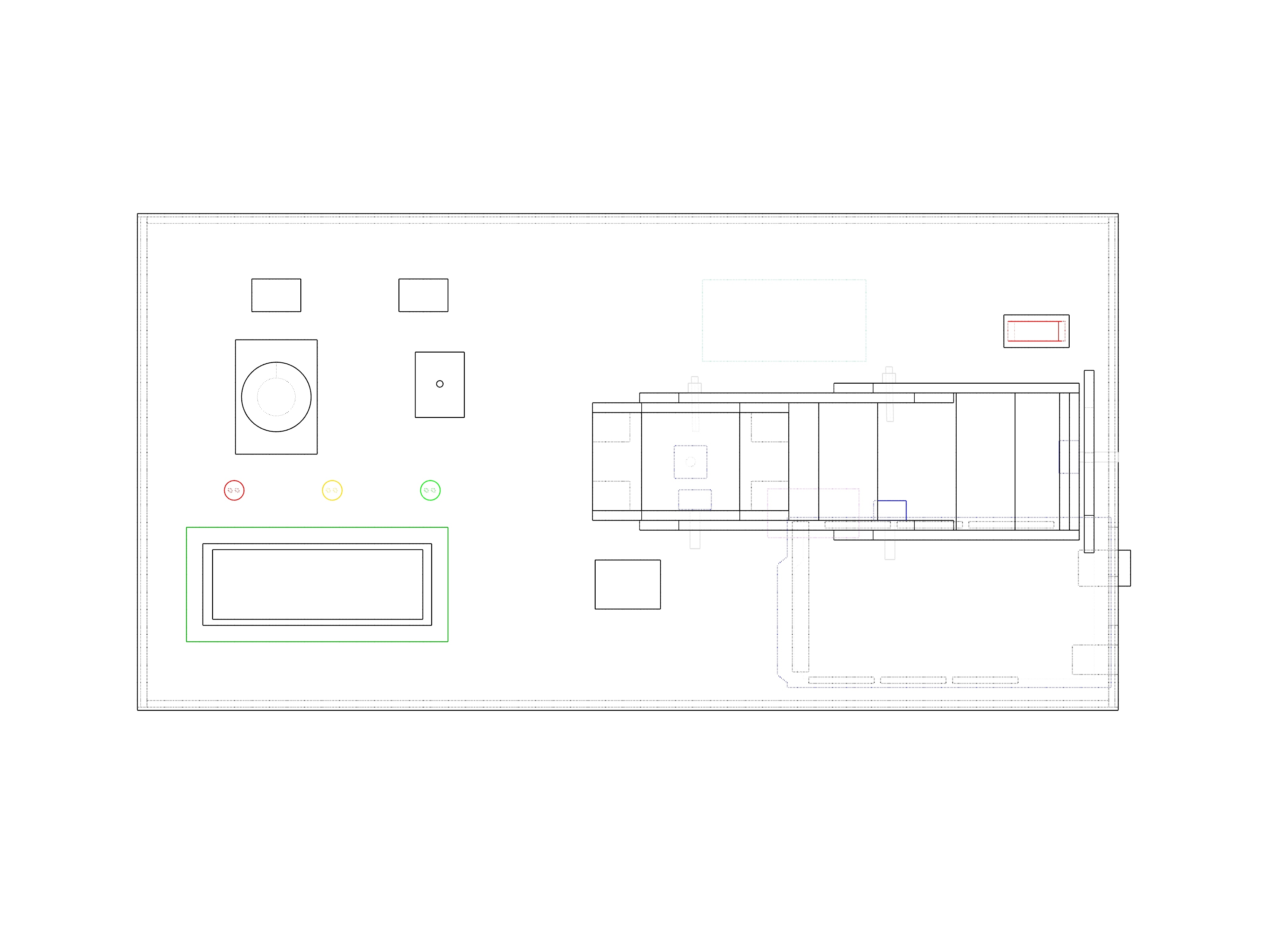
The main design intent was to utilize the easily accessible materials. Thereby, we mainly used foam boards for the mechanical part of our design. In all probability, the declared dimensions were selected considering the size of our pieces and their comfortable usability. Nonetheless, you can place the pieces freely on the foam boards and open the holes in respect to the size and place of your components.
Before starting to build your physical model, it is recommended to check the last section of this article named “Outlook and Tips”.
1. Controller Board
- Cut the pieces of the box out of 3mm-thick foam boards. The dimensions of the overall width, depth and the height of the box are 15 cm, 30 cm and 6 cm respectively. Cut two holes on one of the short edges (corresponding to 6 cm x 15 cm part) in order to the plug of the battery and the USB of your Arduino.
- On the top plate (corresponding to 15 cm x 30 cm part) , you will have all the controller components for the Physical Twin project, which are:
- An on-off switch button: Saving the battery
- Three LED lights: Showing different modes of the code(train, record and play)
- A small physical twin(replica of the robotic arm): Training the robotic arm
- An LCD display: Informing the user about the mode and the angles of the potentiometers A tactile button: Changing the modes of the code
- A joystick: Moving the wheels of the car
We opened 6 holes on the top plate. Those holes are for the on-off switch button, the LCD display, for the wires of the tactile button, joystick and the replica. In addition, we needed screws for the attachment of the Arduino Mega from the inside; joystick, tactile button and LCD display from the outside.
3. Build your small 4-axis robotic arm as a small replica of your robotic arm. On one side, you can have the potentiometers which will send its angle values to the Servo Motors on the robotic arm via NRF24L01 Modules, whereas on the other side you can have the screws and bolts for the stability of its axes. After building your small physical arm, you can make a hole on the control board and attach it to the top plate.
2. Robotic Arm
Dimensions of your robotic arm pieces will depend on the pre-defined reaching capacity of the arm, besides the power, size and the weight of your Servo Motors.
The axes of the robotic arm includes three different bodies and one end effector part. Before building each body, you need to check the size of your pieces by considering the dimensions of your Servo Motors. Due to the depth of the motors, each body is built by horizontally shifting its neighbor body. Shapes of the bodies can be decided considering their structural and aesthetical properties. This is how we did:
- For the case, we used a 5 mm foam board and started modeling the robotic arm by cutting a 10 cm x 10 cm base. Afterwards, we incrementally formed the final shape.
- The first body is built mainly by the shape of the trapezoid that has longer dimensions on the vertical side. This shape not only helps distribute the forces, but also offers the base for the second body. Horizontal supports are added to the front and back of the first body in order to ensure the stability of the axis. In addition to the horizontal supports, vertical supports also stabilize the longitudinal axis of the trapezoid shape.
- The second body is built by shifting the first body towards the motor side, due to depth of the motors. This body has a cylindrical shape on the sides, that represents the rotation. It has horizontal support boards on the front and back which reinforce two lateral boards. It has screws and bolts on 4 points: 2 for the motors, 2 for the other side of the motors for rotation.
- Although the third body has a circular shape on the back where it connects to the second body, its front part which is the neighbor of the first axis has a straight edge with the aim of ensuring the stability of the last axis. Similar to the second body, horizontal boards support the two sides.
- The end effector has 180 degree rotation capability and offers a ground for the brush to be holded.
- Screw the robotic arm base wheels to your base.
3. Robot Car
- For top, bottom, front and back pieces, we used 10 mm foam board, whereas due to the attachment of the wheels to the DC Motors we used 3 mm foam board for the sides. The dimensions of the overall width, depth and the height of the box are 21.9 cm, 29.9 cm and 9 cm respectively. You can cut the corresponding side pieces accordingly.
- For the sides, cut holes for the HC-SR04 Ultrasonic Sensors and the connection of the DC Motors to the wheels. DC Motors will be located inside of the box and the wheels will be attached to them from the outside. Thereby, the hole will be there for the connection stick that stands in between those pieces.
- The height of your front wheel needs to be adjusted considering the ground clearance of the attached back wheels. If the front height is longer, open a hole for your front wheel on the bottom 10 mm foam board piece. If so, in order to hold the front wheel stable, you might need additional support pieces inside the box.
- Drill two holes on your 10 mm front piece for the HC-SR04 Ultrasonic Sensor.
- Create an opening for the battery switch button at the back.
- Open two holes on the top plate: One for the servo motor of the robotic arm that corresponds to its first axis. Another one that is 1.5 cm x 2.5 cm for running the wires of the motors inside.
- You can glue all the parts except the top plate and attach your robotic arm on to it. After placing all the electronics inside and guaranteeing the smooth communication of each of your components, you can glue the top plate, place your painting box there and let the Physical Twin express its artistic potential!
Downloads
Outlook and Tips
-Unless one has an Arduino MEGA, utilizing an Arduino UNO with an ethernet shield is a possibility. With this option, less steps will be recorded.
-The potentiometers on the small replica have a strong effect on the control of the robotic arm. Consequently, it is recommended to ensure the precision of the potentiometers, before attaching them on to the model.
-Before building the final physical model of the robotic arm, ruminating about the motor weight/robotic arms’ length ratio is essential. Especially if building a model in different scales than the aforementioned sizes is considered, making prototypes will be helpful to adjust the stability and the reach of the arm.
-Recommended tests of the electronic parts can be listed as following: 1. Checking the NRF24L01 Transceiver modules’ data transfer. 2.Testing the movement of the robotic arm without the small replica with the help of the potentiometers. 3.Testing the movement of the robotic arm again but by using the small replica that has the potentiometers attached on itself. 4. Checking the movement of the wheels and its connection with the joystick. 5. Testing the collision avoidance of the distance sensors and ensuring its proper communication with the joystick.
-Precise physical models require accuracy in the sizes of the pieces and the holes on them. Therefore, before building the physical models, modeling the components and the overall model in exact sizes by using computer-aided design application softwares is beneficial.
-If you are using a foam board for your physical model, in the parts where you connect two edges, we recommend you to cut the foam pieces apart and just have the paper part of the board for one side. This way you can cover the sides and the thicknesses of your board hence, make your model visually more pleasing.
References