Physical Reconfiguration of Digital Anatomy
6357 Views, 39 Favorites, 0 Comments
Physical Reconfiguration of Digital Anatomy
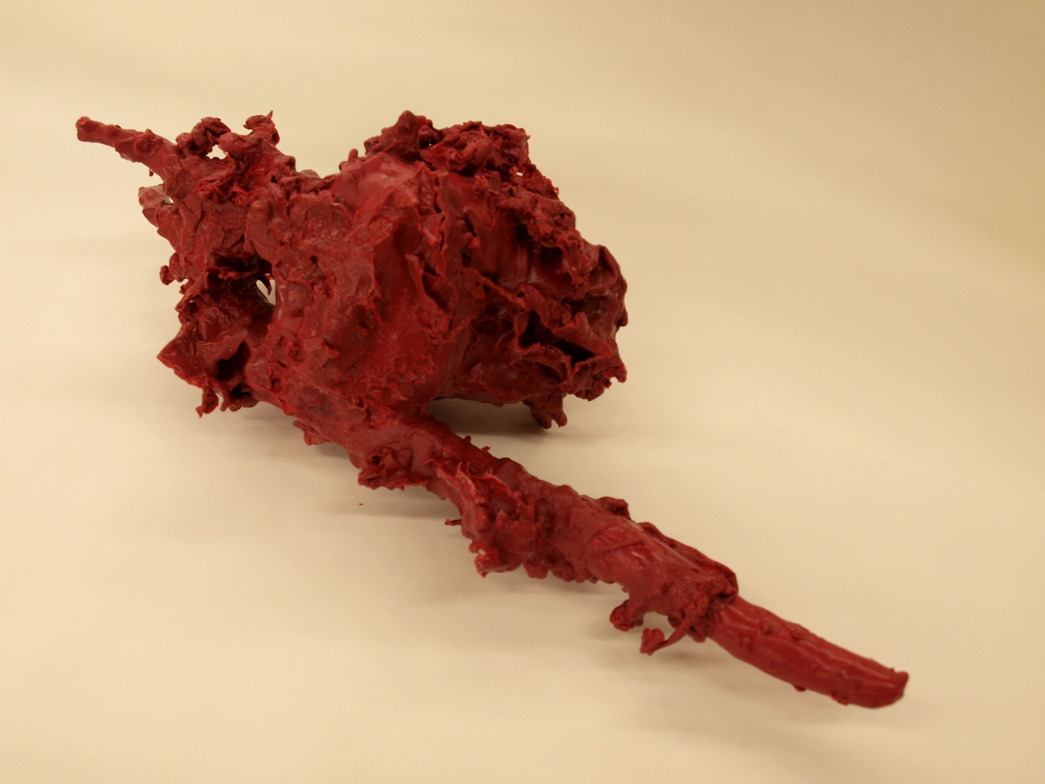
This project had its roots in my fascination with anatomy, and my own organs and internal processes. Due to various childhood surgeries, I've had to get a number of MRI's, and the resulting images are amazing. I love the concept of being able to see the complex internal organs through the barrier of skin.
This instructable will show you how to create three-dimensional forms based off of photographs, mill out a foam object from those digital forms, and use wax to create a physical representation of the "digital anatomy."
This instructable will show you how to create three-dimensional forms based off of photographs, mill out a foam object from those digital forms, and use wax to create a physical representation of the "digital anatomy."
MRI Images to 3D Object
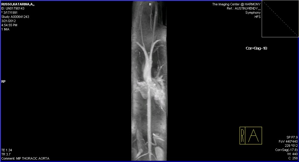
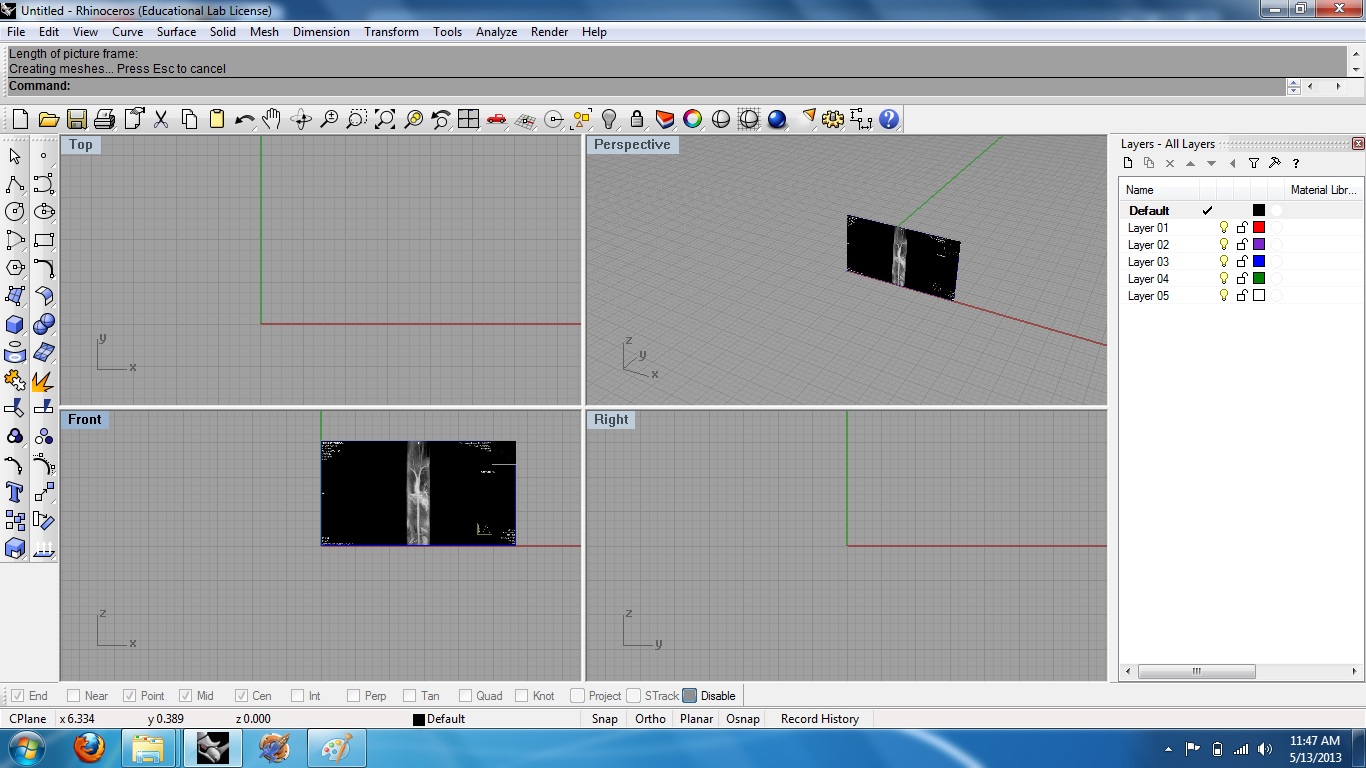
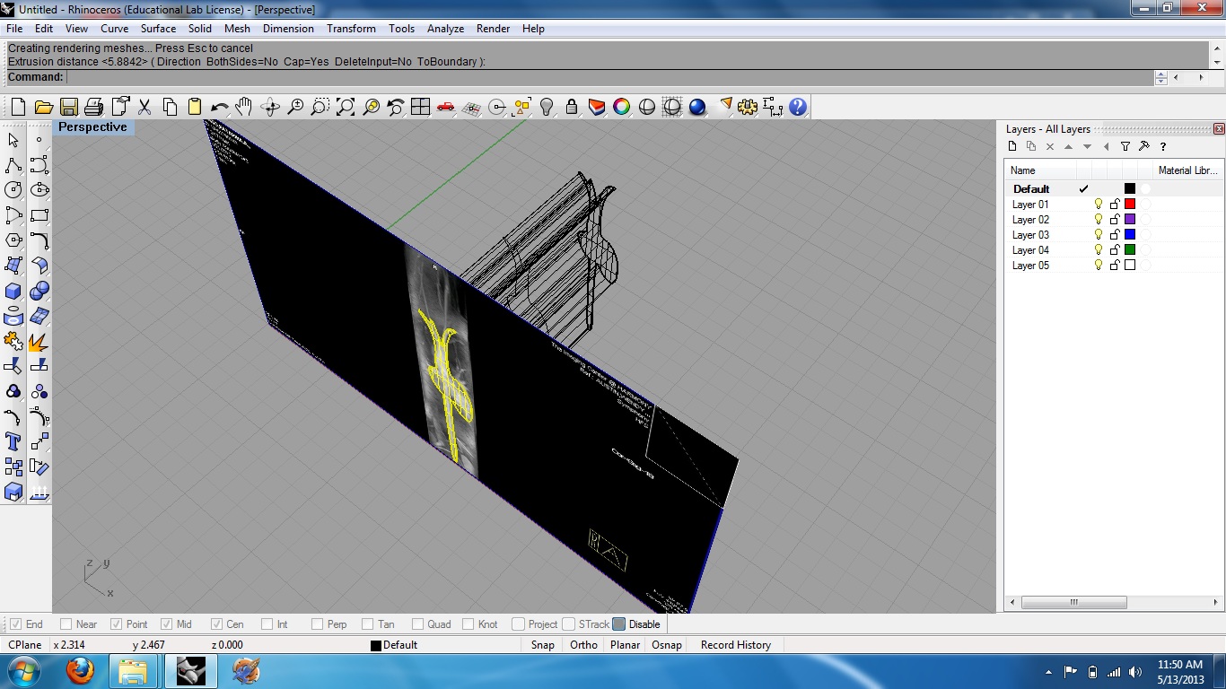
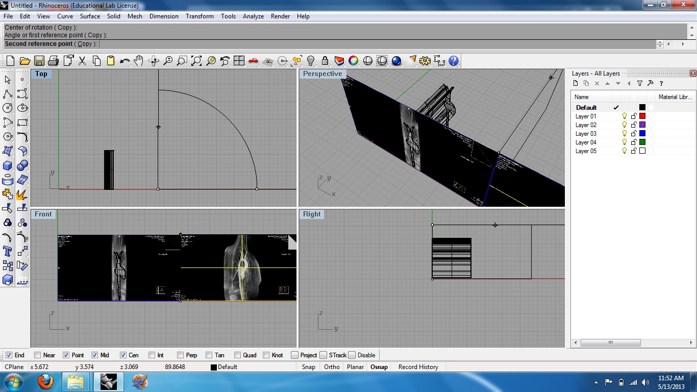
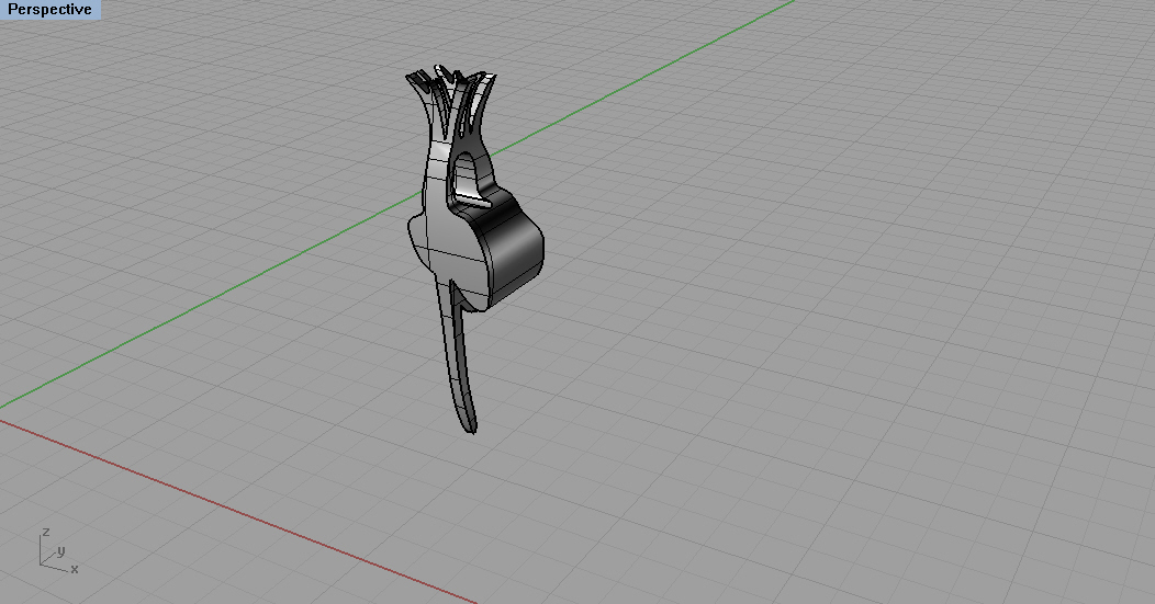
First, insert an image (Figure 1) into Rhino using the "picture frame" command. This will result in an image that is able to be moved and scaled. (Figure 2)
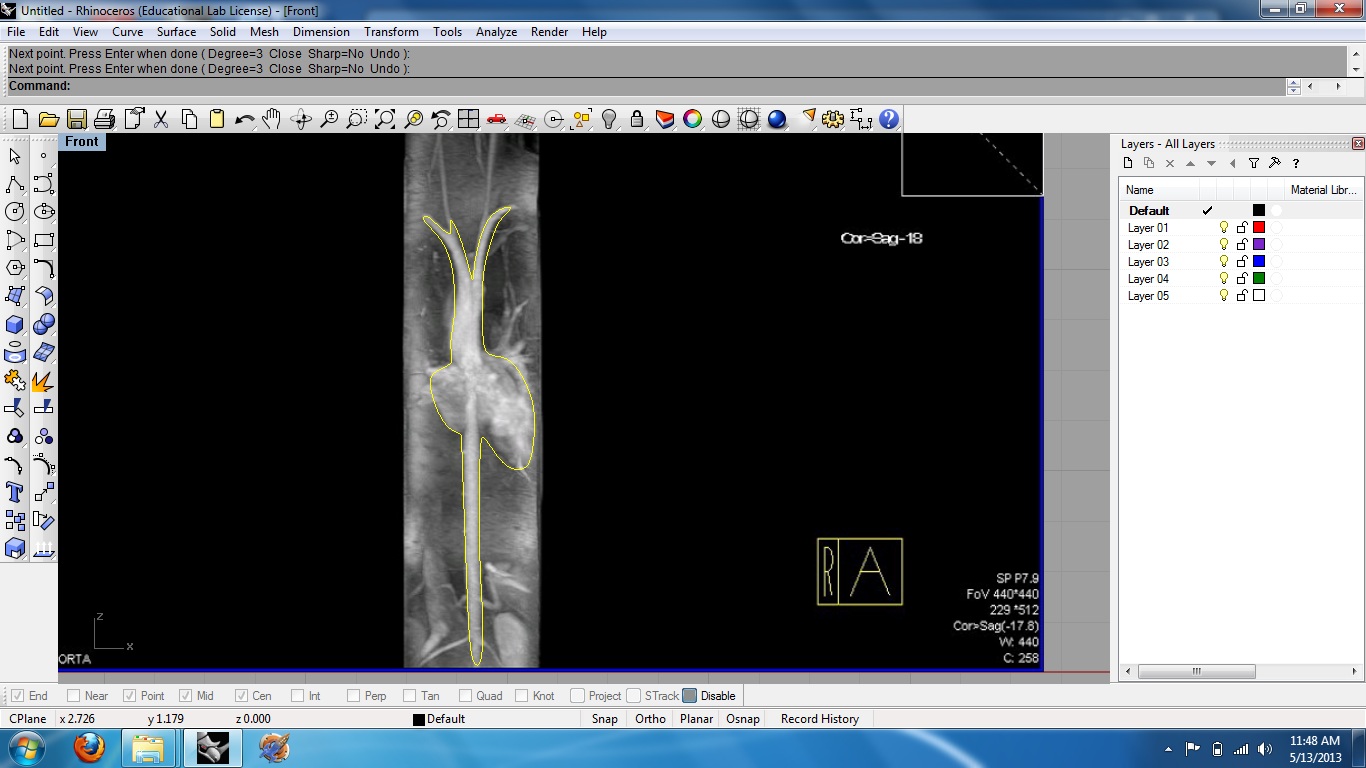
Use "control point curve" to draw a line around the object you wish to make 3D, in my case it was my heart and aorta. (Figure 3) It is important to turn Osnaps off for this, so that the line will be on one plane and not snap elsewhere where you don't want it. Use the "patch" command to create a surface from the closed line, and then use "extrude surface" to create an extension that can hold volume. (Figure 4) Make sure that 'cap' is selected, so that the extruded ends are capped and the figure is solid.
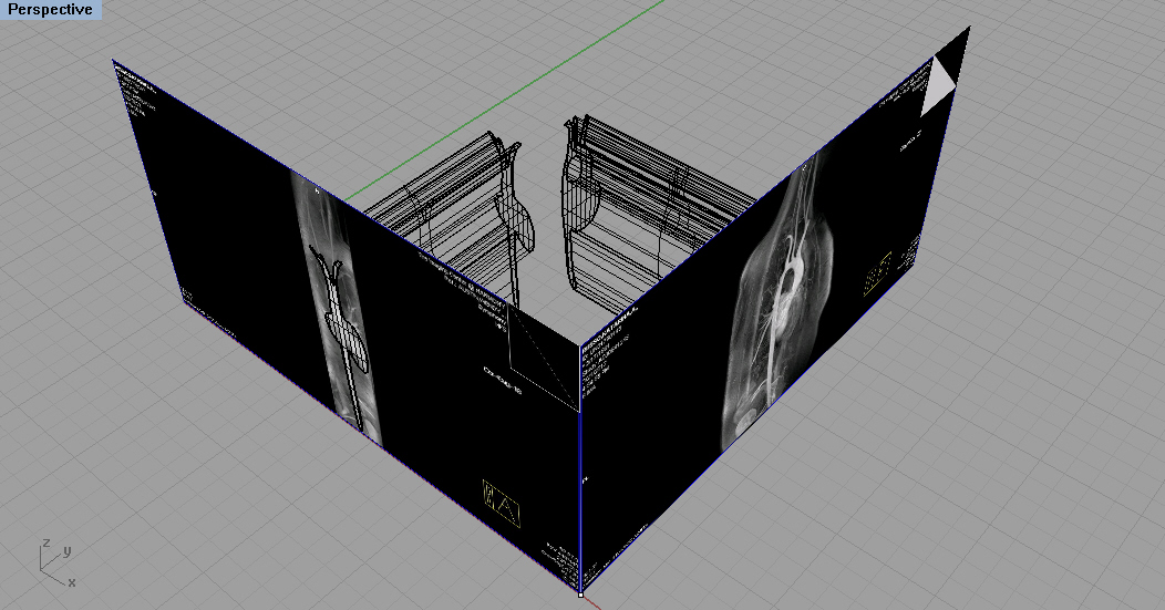
Insert another image, with the same "picture frame" command. This image should be another view of the same object. For example, if the first image was of the front of the object, the second image should be of the side of the object. Rotate the second image 45 degrees. (Image 5)
Perform the same process on the second image: control point curve, patch, extrude surface. You now have two solid objects. (Image 6) Depending on where you place the second image, the tracing line may or may not be directly on the image. If it is not, the process works just as well. However, for patch to work correctly, make sure that the line is not curved through multiple coordinate planes.
Arrange these two objects so that they intersect one another. (Image 7)
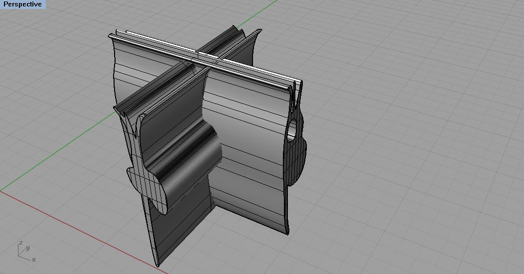
Use "Boolean2Objects" and select 'intersection.' This should result in a three-dimensional object that is roughly the shape of your desired piece. (Image 8)
Editing Your 3D Object
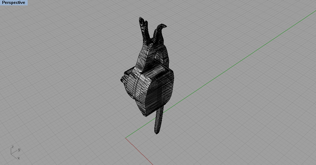
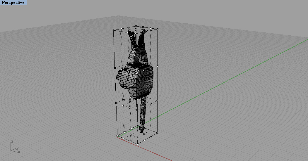
Use various boolean, trim, and split processes to edit off the extra parts you don't want. (Image 9)
The "cage edit" command is useful for very gentle edits of your object. (Image 10)
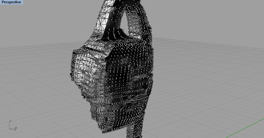
To get more detailed edits of the object, transform it into a mesh and turn control points on. (Image 11) While moving points around, it helps to use the nudge function in various viewports, as dragging them with a mouse results in extremely skewed objects.
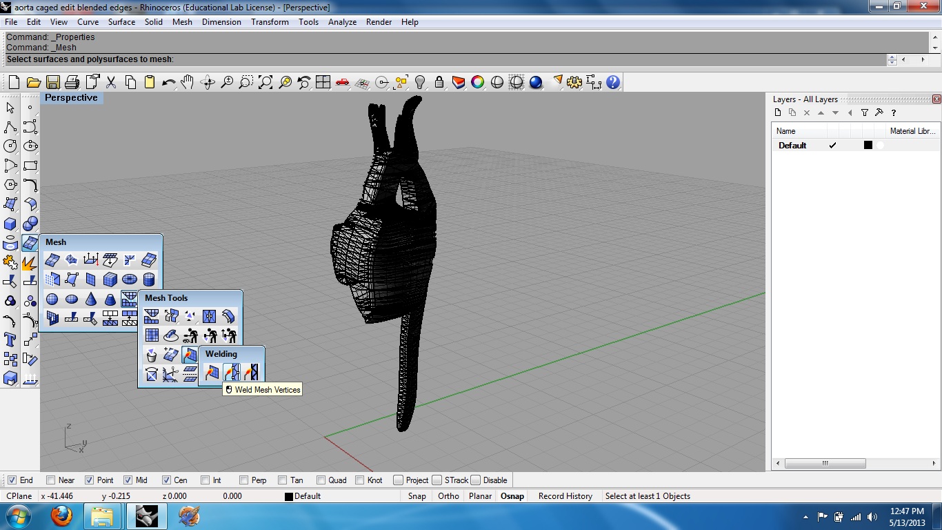
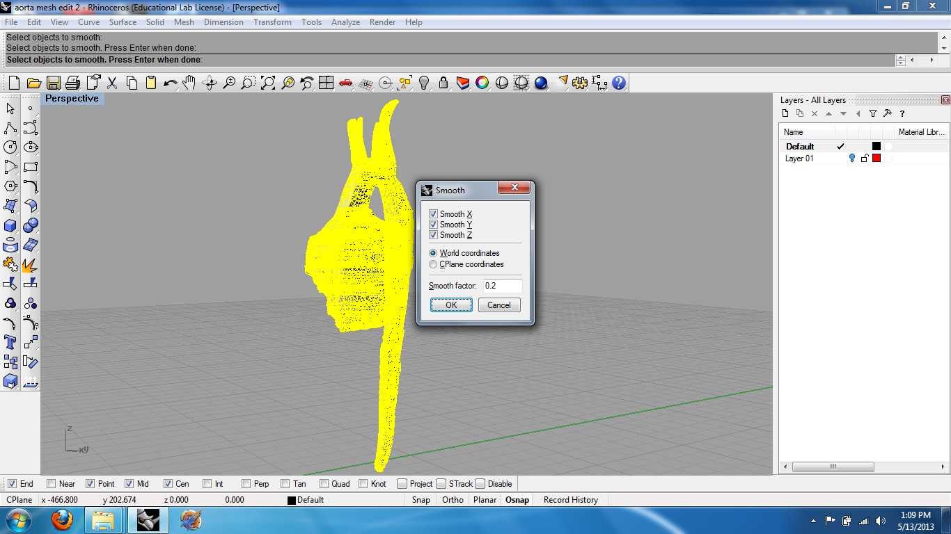
When satisfied with the arrangement and layout of your object, you can smooth it further by using the weld command to "weld mesh vertices." (Image 12) Once welded, type in "smooth" in the command line and hit 'OK.' (Image 13) You can do over again until you get the desired shape.
Fixing the Mesh and Arranging It for Milling
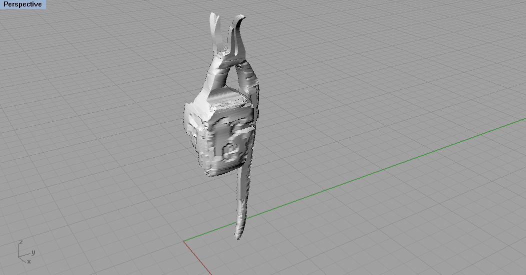
Your mesh will be full of holes, and will be either very difficult or downright impossible to mill or print at this point.
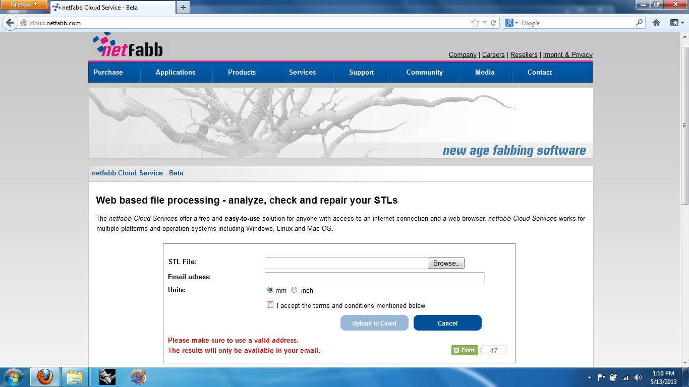
Use the netFabb application online to fix your file. (cloud.netfabb.com) Save your file as an .stl, and then upload it to the cloud. Some kind of magic happens, and your fixed, solid .stl will be emailed to you. (Image 14)
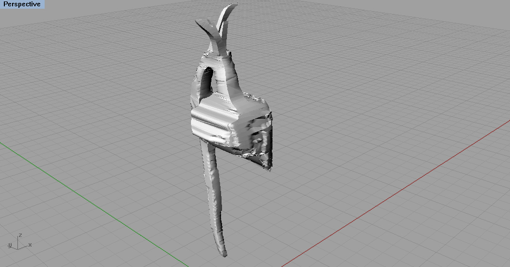
Here are some images of my own file after receiving it from netFabb. (Images 15 & 16)
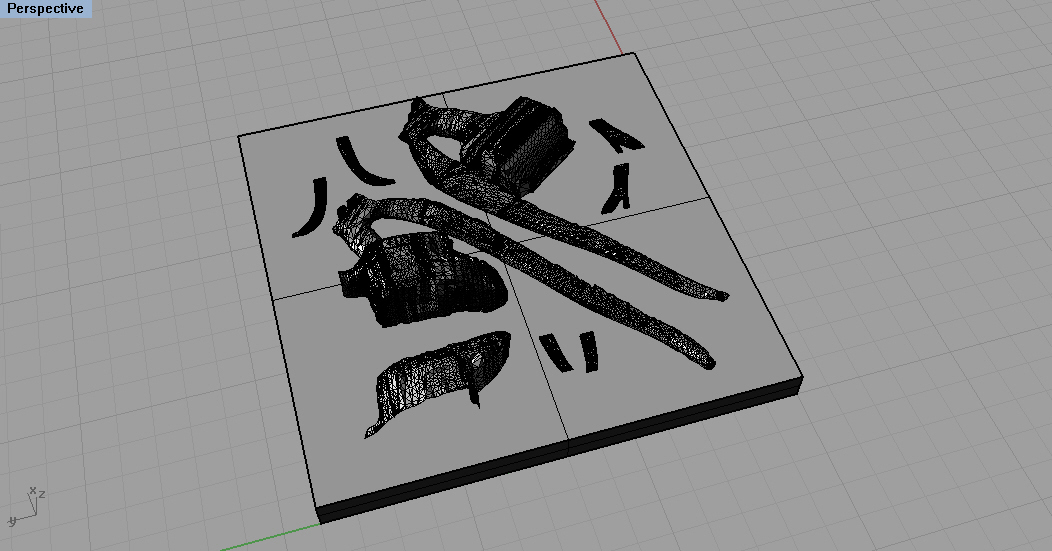
In order for me to mill out the heart and aorta, I had to split it up so that there were no undercuts. (Image 17) If you were using a 3D printer, there would be no need for this and the object would be ready to go.
Wax Coating, and Final Drawings
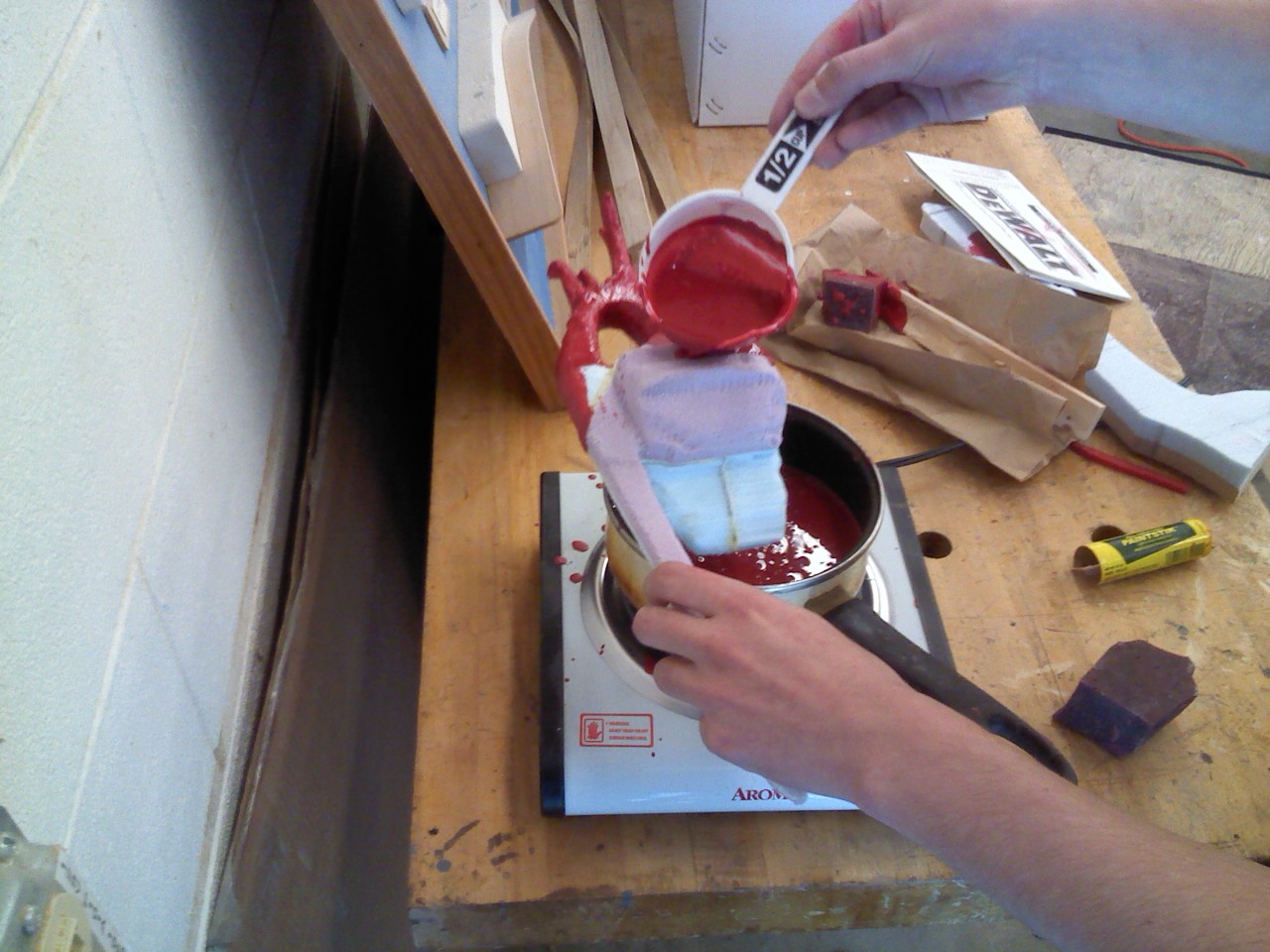
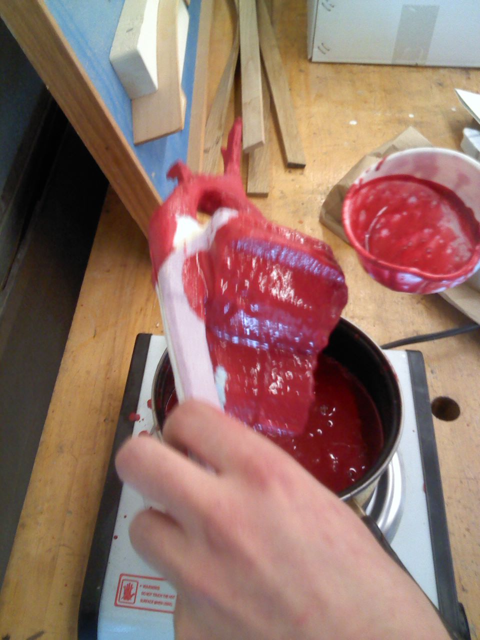
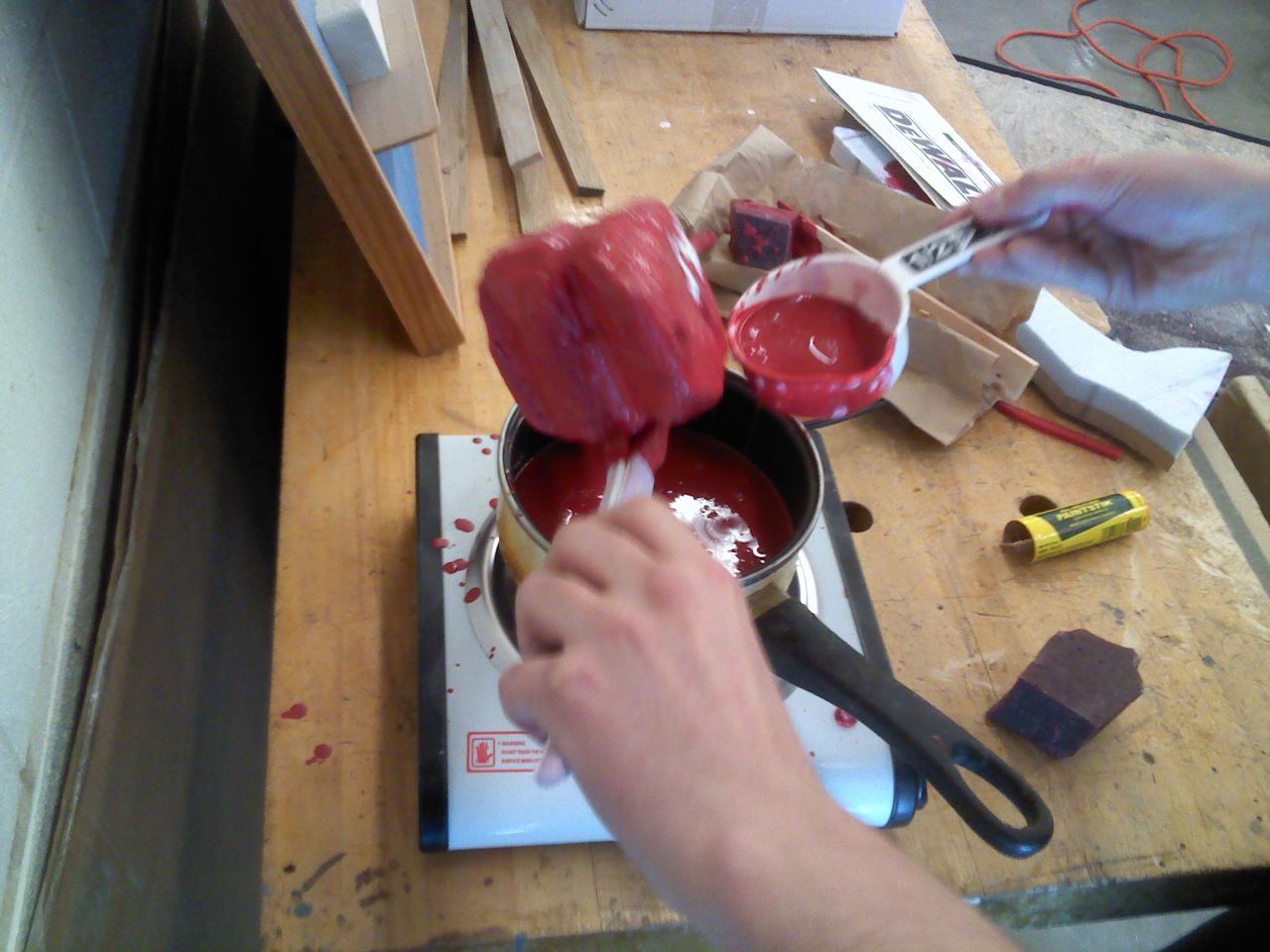
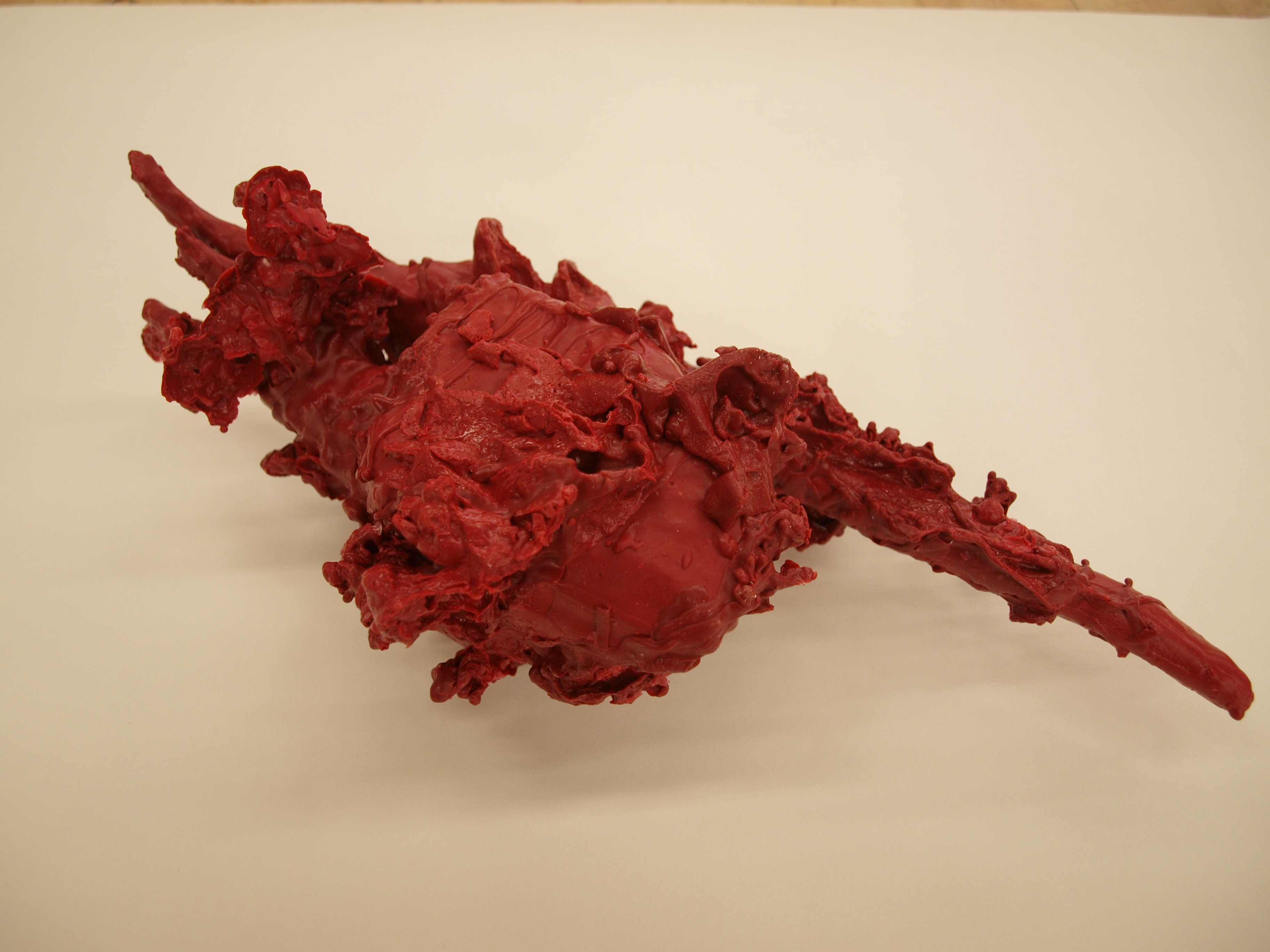
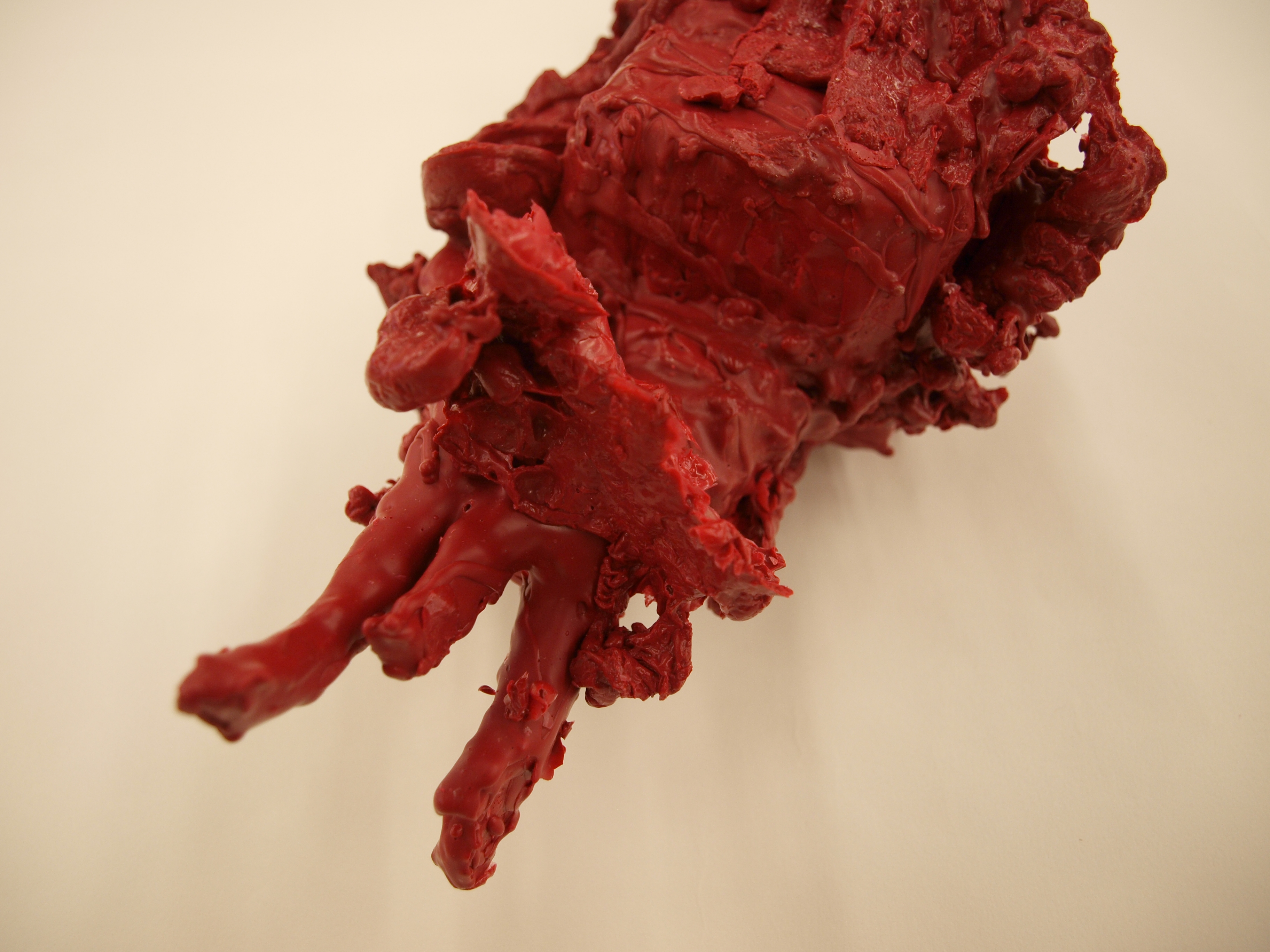
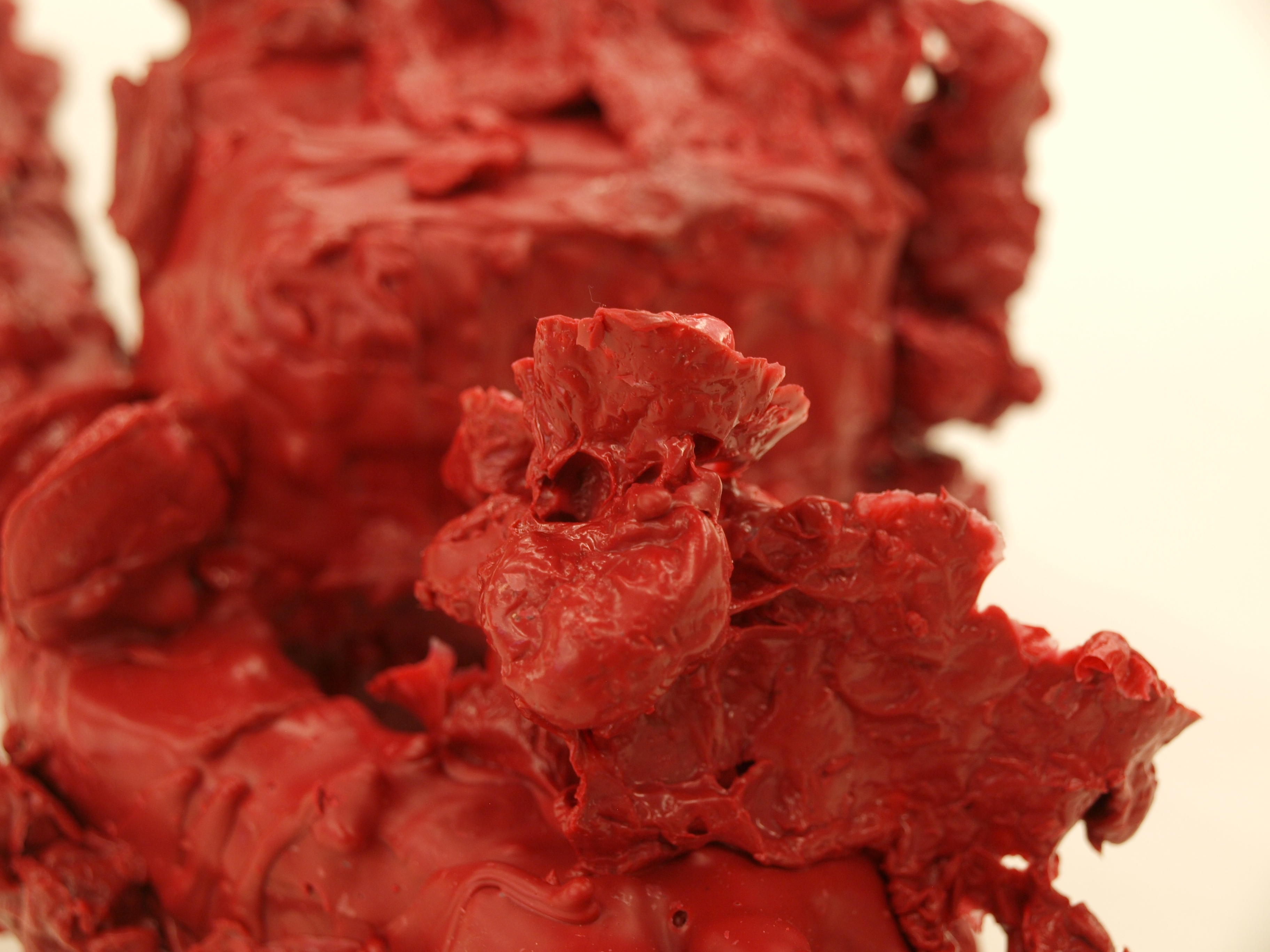
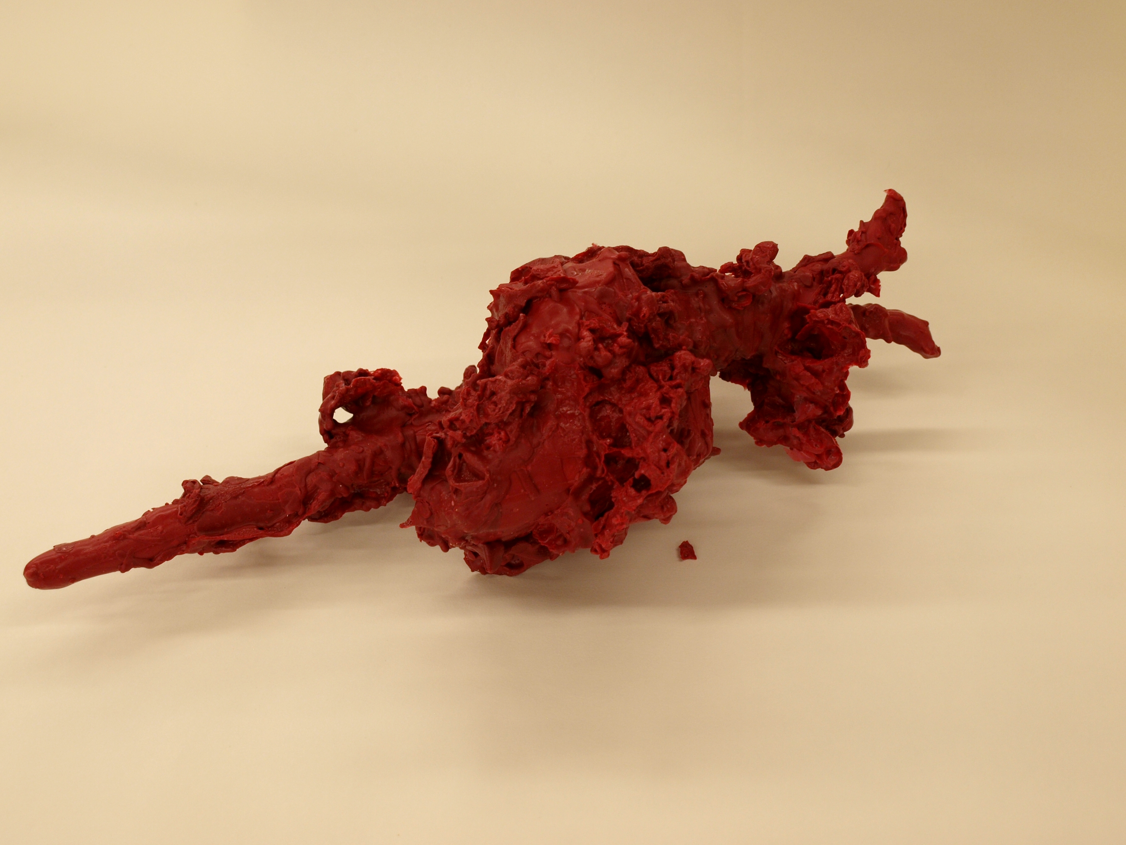
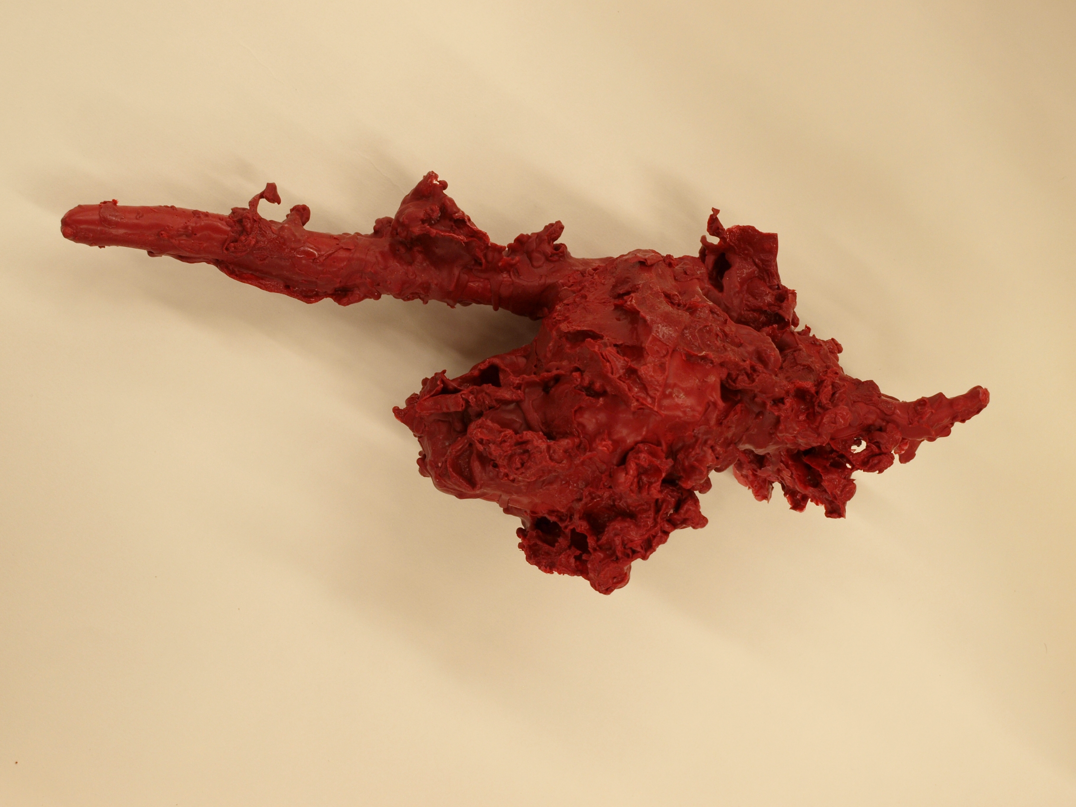
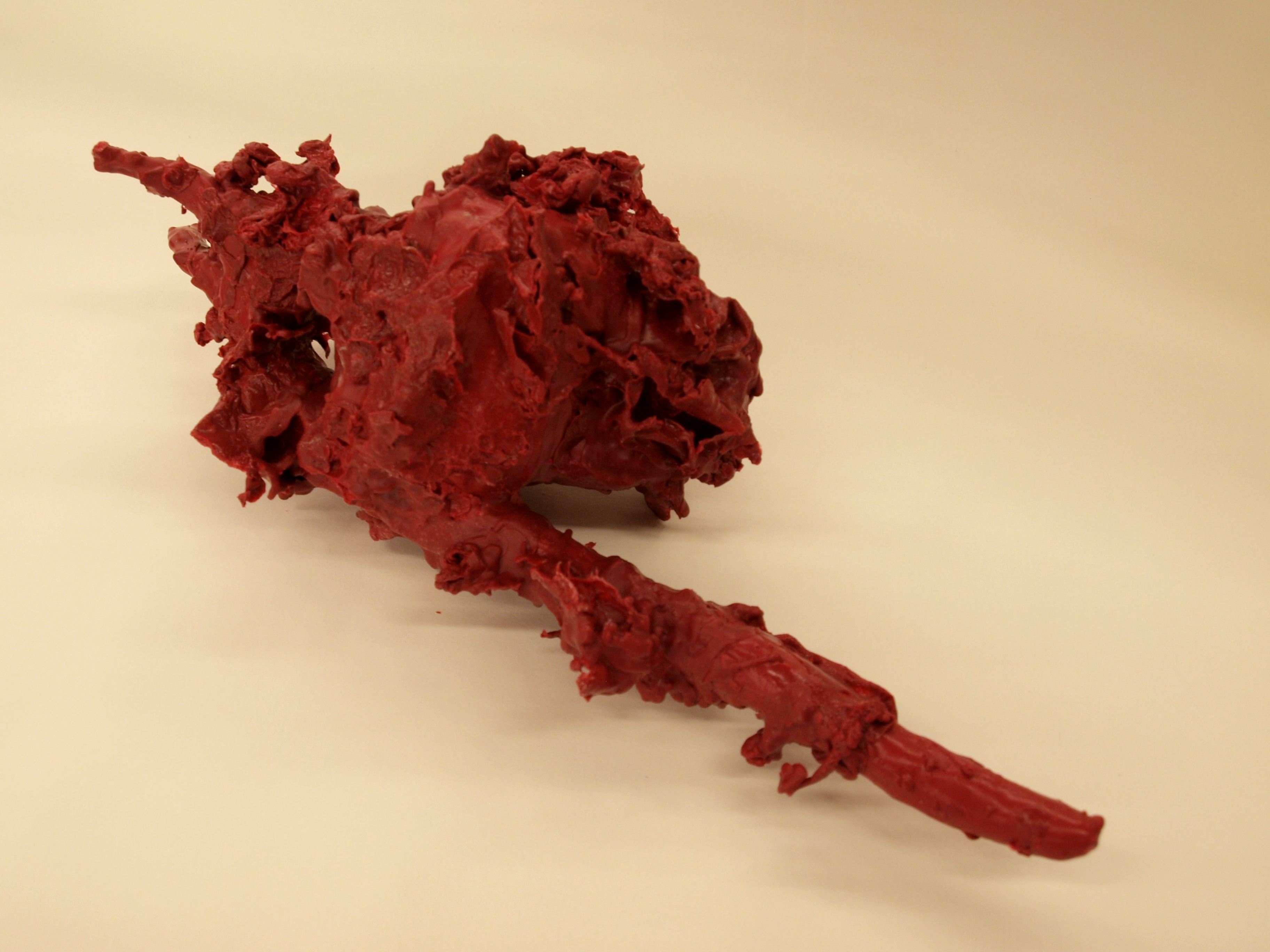
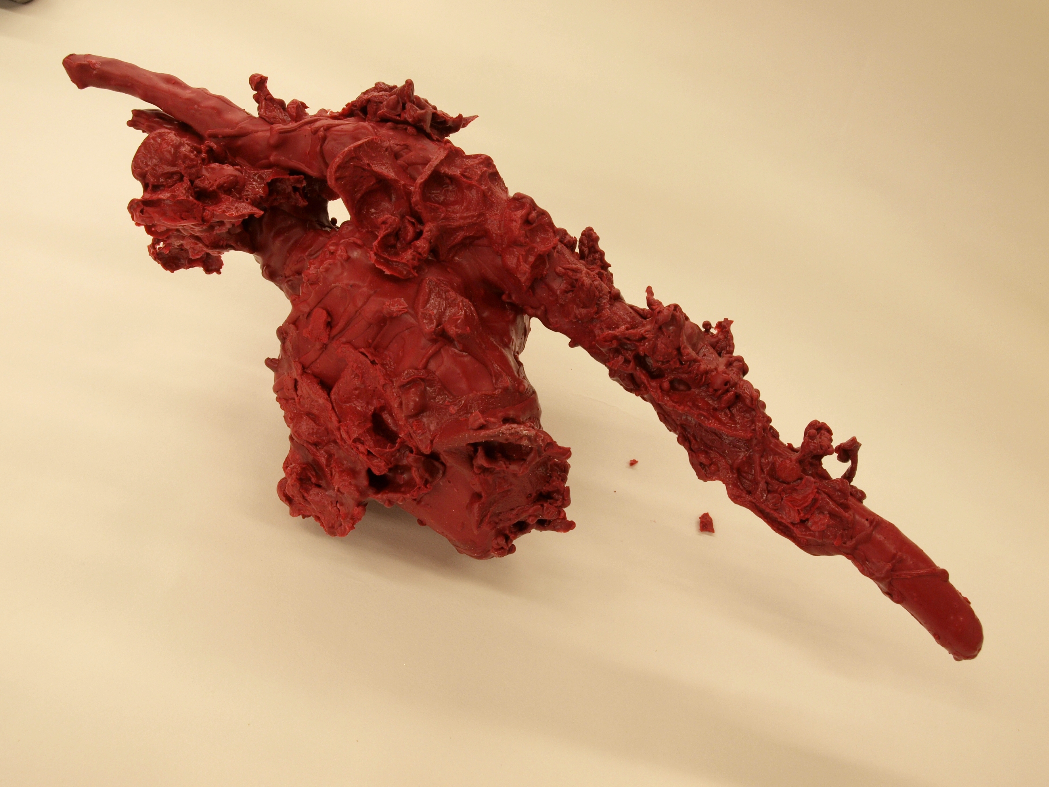
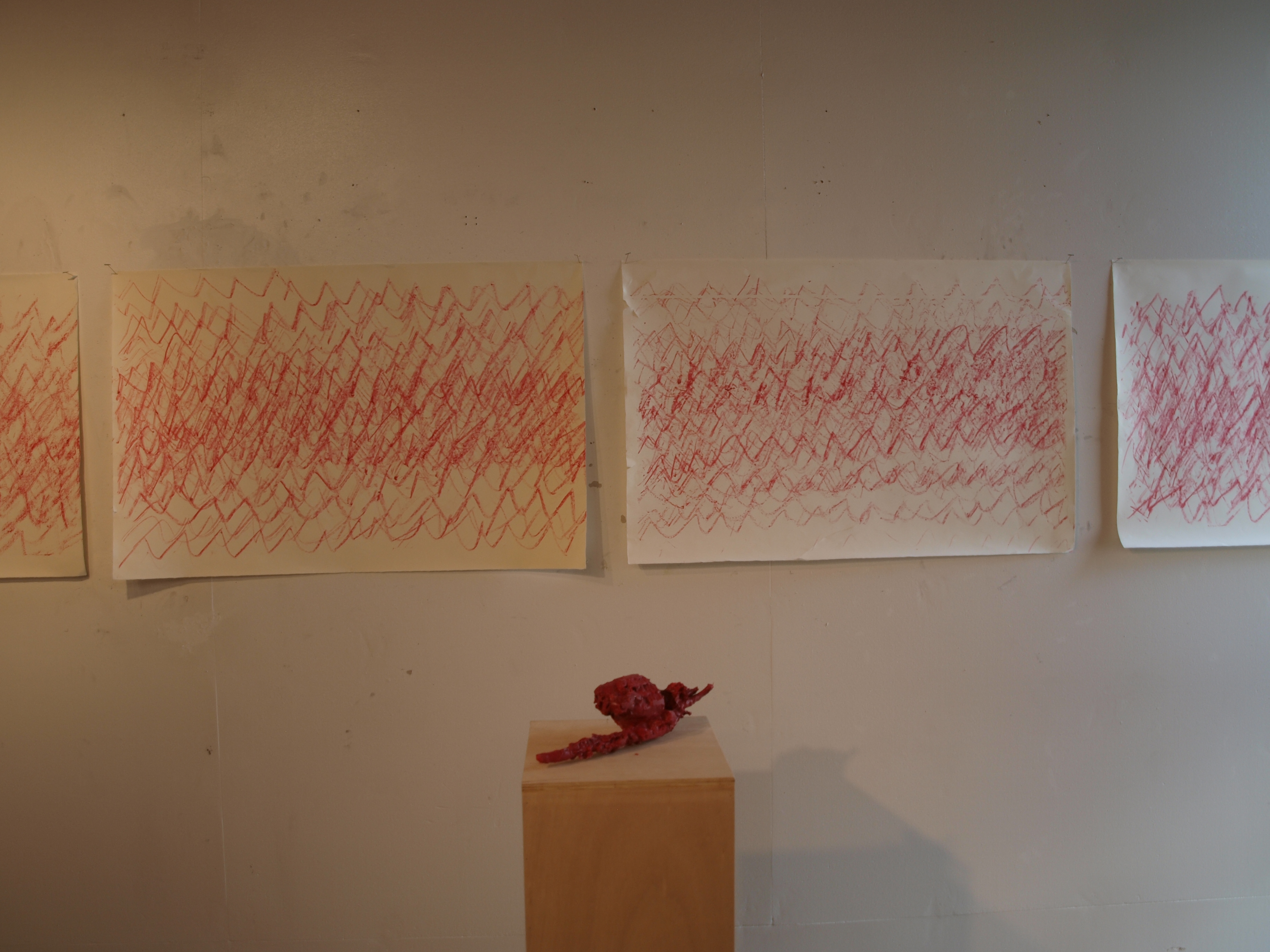
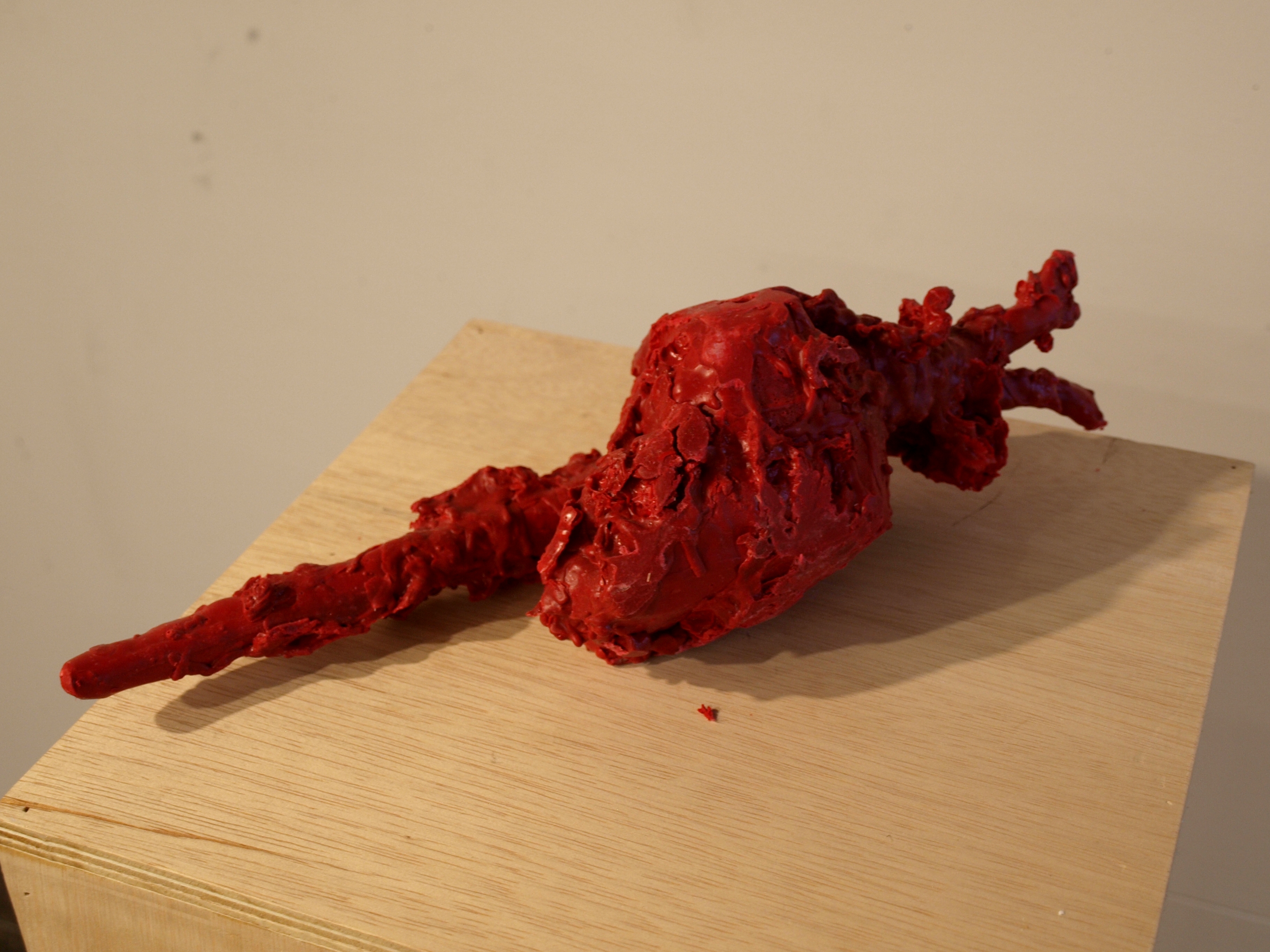
Using a mixture of melted red wax and cattle marker, I coated the heart and aorta with a crayon-like surface. (Images 18-20)
While dipping the heart into water to cool the wax, I discovered the amazing things that happen when melted wax is poured into water. I used a process where I would pour the wax onto the heart while dipping it into the water, and it resulted in some amazing, fungus and sea life-like forms. (Images 21-27)
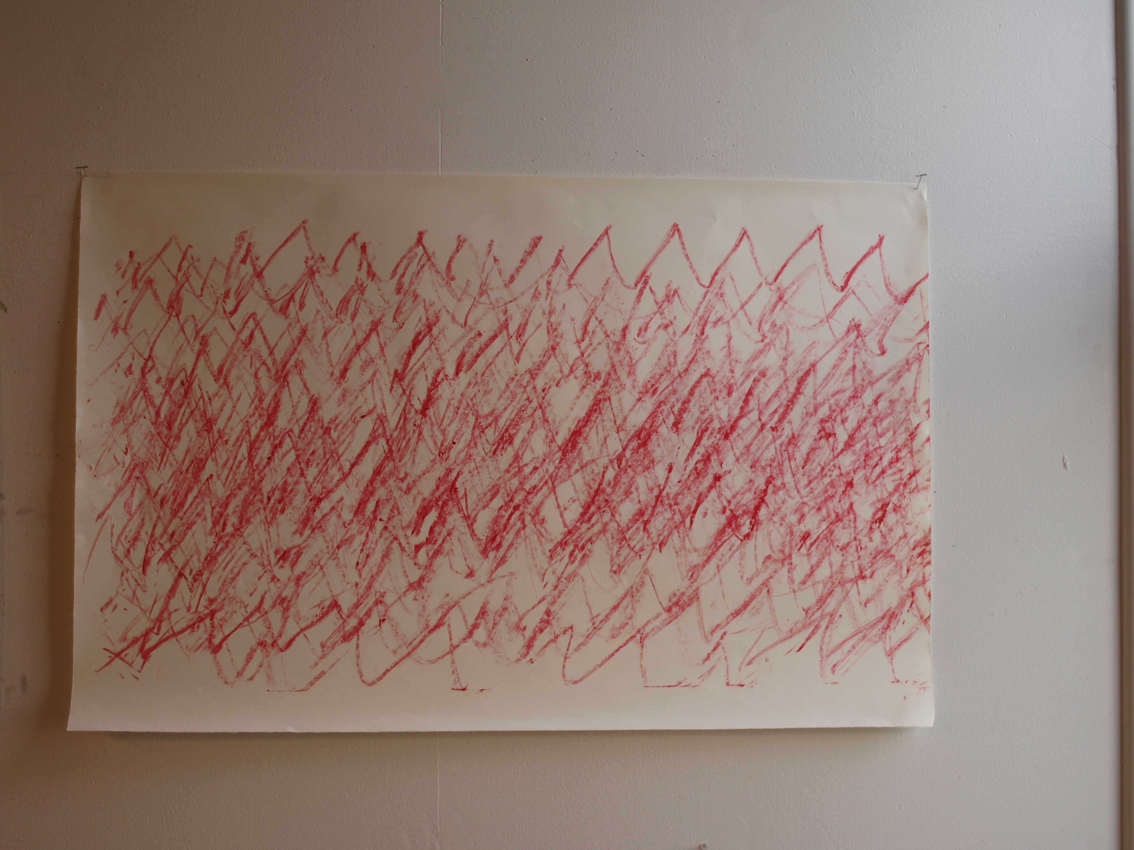
Then, I closed my eyes, and while taking my pulse, I drew with the heart-crayon so that every time I felt a heartbeat, I would draw a peak. Over and over, this resulted in a physical representation of an internal process, using a physical representation of an internal organ, derived from a digital representation of digital images of my internal organs. (Images 28-30)
Fun!